 Jie Shen
 Wen qi Dong3†
- 1State Grid Jibei Zhangjiakou Wind and Solar Energy Storage and Transportation New Energy Co, Ltd., Beijing, China
- 2School of Electronics Engineering, Beijing University of Posts and Telecommunications, Beijing, China
- 3Hebei Province Wind and Solar Energy Storage Combined Power Generation Technology Innovation Center, Beijing, China
To accurately simulate the interference mechanism of information communication between unmanned aerial vehicles (UAVs) in the future global grid system, a type of control based on dynamic simulation of the satellite communication network and robust fault tolerance with a stochastic delay uncertain network system is proposed. Based on the imaginary future of the global energy Internet, with unknown information and communication interference, we established a UAV model from sensor to actuator network delay using a robust, fault-tolerant control algorithm and a satellite communication network model that combined the controller’s mathematical model. The simulation results showed improved power transmission capability and communication coverage ability of UAVs by using the network fault-tolerant control mechanism with uncertain network delay and information communication interference. The stability and anti-interference performance was also significantly improved. This algorithm provides a strategy for the future development of global energy Internet.
1 Introduction
With rapid economic globalization and transformation of energy structures, global energy Internet is developing as a main body of cross-regional transmission and transportation project construction. This Internet aims to promote global resource sharing, efficient energy, and clean energy development to promote construction of the world’s ecological civilization (Qing et al., 2009). These efforts have focused on the advancement and development of special high-voltage projects. Compared to EHV high-voltage transmission lines, the structure of UHVs is more complex (Liu, 2009), with higher specifications required in all aspects. Transmitted electrical energy from wind farms is connected to UHVs; however, grounded, wireless communication cannot cover wind farms and satellite communication rates cannot meet the requirements. Thus, the only feasible solution is to use UAV clusters for line patrol and inspection.
In long-term transmission line operation and maintenance, the timely detection and rapid elimination of security risks, to ensure safe and reliable line operation, is particularly important. UAVs have recently been used for power inspection to promote the development of new technology, guarantee its safety, ensure inspection quality, and improve inspection efficiency, with good results achieved.
Multi-rotor UAVs are mainly used at low-altitudes and in complex environments with obstacles such as cross-crossing lines, road bridges, buildings, and trees, as well as strong electromagnetic fields generated by UHV transmission lines, signals, and other unknown interference with information traffic. Failure to appropriately handle the UAV, the transmission line, and the surrounding environment can have consequences ranging from UAV crashes to personal and power grid security incidents, resulting in large-scale power outages. Therefore, study of the safety of using multi-rotor UAVs in proximity to UHV transmission lines is important (Xin-Zhe, 2012).
Actual flight drone control mainly faces two threats: hard killing and soft killing. Hard kill generally refers to physical destruction due to collision. In general, in soft killing, the most simple and rugged way is to interfere with UAV information and communication signals. Whether civil, commercial, or military, most UAVs face such interference. For the control of UAVs, transmission intensity is limited due to the transmission distance; moreover, the communication signal transmission strength from satellite or terrestrial base stations is relatively weak due to harsh natural environments and other unavoidable factors (Yong, 2013). Certain directional radio frequencies are likely to interfere with UAV information and communication transmission. Such signal interference prevents UAVs from obtaining accurate self-coordinates, leading to a lack of UAV control, which interrupts the inspection task (Fei, 2014). These effects constitute a long-range threat to UAVs.
UAVs will play an increasingly important role in electric power inspection, and efforts are in full swing to promote the development of methods to fight hard and soft killing and subsequent damage, which will become a new research field (Bouadi et al., 2008). The main focus of this study is soft and hard kill strategies to ensure that UAVs can maximize inspection tasks for further research simulation tests. The future of global grid UAV patrol is to provide a certain strategy (Ioannou and Sun, 1996).
The simulation in this study considered a four-rotor electric UAV as an example. This study proposes a robust, fault-tolerant control mechanism for information communication networks with stochastic delay uncertainties for UAV fleet systems for future global grid inspection. This mechanism ensured the stability of the UAV fleet flight control system when performing detection tasks in the face of different interference signals, and showed good anti-interference performance. Regarding partial and drift faults, the mechanism showed good fault tolerance performance when the actuator was interrupted. The physical structure of the model is shown in Figure 1.
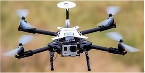
FIGURE 1. Physical model of a four-rotor UAV.
2 Establishment of a mathematical model for an electric drilling four-rotor UAV
The spatial and body coordinate systems of the four-rotor UAV are shown in Figure 2.
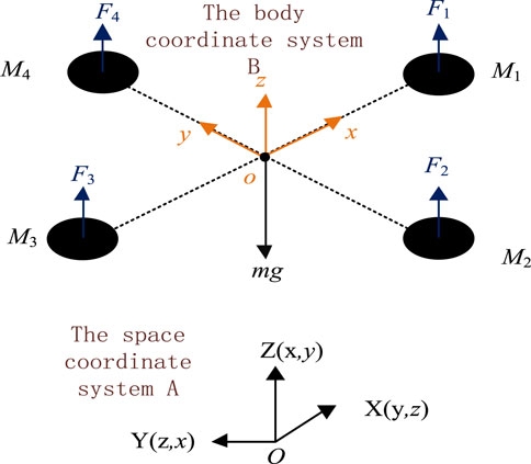
FIGURE 2. Four-rotor aircraft structure model diagram.
Using Newton’s second law, the dynamic model for a four-rotor aircraft can be expressed as follows:
Here,
In which the body revolves around three moments of inertia of the coordinate system for
The mathematical model of the space coordinates of the four-rotor aircraft is as follows:
where
3 Design of unmanned assemblies in the future global grid system
The use of unmanned aircraft for the inspection of transmission lines is just beginning. This technology mainly uses the UAV’s modern flight control and image camera recognition for high-altitude long-range rapid detection of transmission lines. UAV-based power line patrol research involves several areas of high-tech collaborative applications, requiring a higher level of research and scientific research. However, compared to traditional methods, this method is more advanced, effective, and lower cost, ensuring safe operation of the line.
Figure 3 shows a block diagram of a hypothetical future grid system under UAV inspection (Wang et al., 2009).
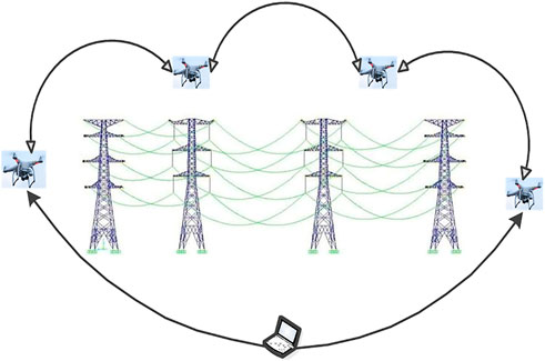
FIGURE 3. Demonstration block diagram of unmanned aerial vehicle group inspection.
4 The establishment of an information communication interference model and its model for possible failure
According to the flight and dynamic characteristics of UAV aircrafts, we choose a robust, fault-tolerant control mechanism with stochastic uncertain time delay networks. The power line inspection process presents many uncertain factors which may delay operating characteristics. Robust control refers to a system affected by interference that maintains the desired performance. Adaptive control is a control method that can correct the characteristics of the system, allowing adaptation to changes in the dynamic characteristics of the object and external disturbances. A fault-tolerant control means that the system has a certain tolerance to faults in the event of an unknown failure; that is, lower sensitivity, to maintain performance indicators in the event of failure. By adopting robust adaptive fault-tolerant control, the performance of UAV systems can be well controlled. We also can improve their ability to resist hard and soft interference, increasing the information transmission and coverage abilities of UAVs (Zhang et al., 2014).
During inspection tasks, to facilitate accurate inspection of the object by confirmation, UAVs must upload high-definition photos or video, which requires a high-level camera as well as identification of location, as close as possible to the object being tested. However, as the UAV approaches the target, there are inevitable additional security risks. Hence, if the speed, altitude, and direction of the UAV are not controlled, it may impact the object, causing its failure. In other words, disturbances can occur during the task; such interference can be divided into hard kill jamming and soft kill jamming. Soft killing interference mainly refers to interference in electronic information communication caused by electromagnetic interference due to high-voltage electricity (Mokhtari et al., 2005). In these situations, UAVs cannot be well controlled due to restrictions in information transmission and coverage capacities. Hard kill interference mainly refers to harsh environments such as strong winds and heavy rain, and physical interference such as physical damage due to collisions. In addition, “hard kill jamming” includes UAV actuator faults, comprising three types of actuator failure, partial failure, and drift fault (Yang et al., 2012).
A. Establishment of a hard-kill interference model
Let
where
The following definitions are made:
Thus,
The mathematical model (4) is expressed as the state space expression:
Thus,
There is a state space expression in the case of a fault condition. The resulting system is as follows:
Thus,
Supposition 1: All states within the system are observable.
Supposition 2: In the case of actuator failure,
Supposition 3: In the actuator failure mode, the control system of the whole UAV satisfies the following condition:
Supposition 4: All actuators of the UAV can fail at the same time.
B. Establishment of a soft-kill interference model
UAVs are likely to encounter electromagnetic interference caused by high voltage during near- or even long-distance power patrol inspection, which leads to uncontrolled UAV flight. Therefore, the study of how to reverse information and communication interference requires the establishment of a corresponding mathematical model so that the UAV can perform the corresponding patrol task better (Yan, 2013).
The dry signal ratio in the interference equation is used to determine the target receiver. To obtain a dry signal ratio, the signal and interference power values at the receiving device are first calculated (Zheng et al., 2013). The signal power
where
The interference power at the target receiving device
where
Filter loss is defined as the power loss caused by the filter that occurs because the receiving device uses a band-pass filter to filter the interference signal of the partial frequency. When the interference signal bandwidth is larger than the useful signal bandwidth, or when the interference signal deviates from the useful signal, the filter will transmit a signal outside its operating frequency. As interference is filtered out, its role will weaken. The following reflects the proportion of interference power to the total power of the UAV:
where
When the entire spectrum of the interference signal passes through the bandpass filter,
Polarization loss is defined as the loss caused by the difference in the polarization direction of the interfering wave emitted by the interfering transmitting device and the receiving antenna. This loss can be expressed by
The control effect when the UAV is controlled remotely is shown in Figure 4.
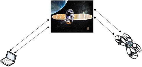
FIGURE 4. Future power grid system under control inspection by unmanned aerial vehicle effect map.
The dry signal ratio,
From the above equation, the dry signal ratio is related to filter and polarization losses and also to the signal (useful and interference signals) transmit power, two sets of antenna gain, and two path losses (Wang and Fu, 2017).
According to the definition of the pressing coefficient
In this formula, the following equation should be satisfied:
However, when calculating the interference power, the spectrum width of the interference signal entering the UAV receiving device is usually not determined; thus, in practice, the following formula is commonly used to calculate the filter loss:
The polarization loss
In which
The path loss difference is generally given by:
In which
To estimate the interference distance in the future grid system, the communication interference equation should first be used to estimate the path loss (Wang and Xiao-Ning, 2012):
In which
Then, we can estimate the interference action distance using a general expression of the path loss difference. That is:
When the LEO satellite communicates with multiple UAVs, a collision-limitation algorithm can be used. In general, when the ratio of the number of code channels to the total number of code channels of the UAV license-free system is
5 Robust fault-tolerant control mechanism for stochastic uncertain network delays during power inspection by unmanned aerial vehicles
In this section, the system control mechanism block diagram is shown in Figure 5, in which the UAV sensor is time-driven work, while the controller and actuator are task-driven work (Wang et al., 2020).
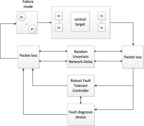
FIGURE 5. Robust fault-tolerant mechanism for uncertain networks with random delay.
Here,
In this formula,
Assuming that the state of the UAV control system considered above is observable via the sensor (Wang et al., 2022a), we can design the following state-dependent feedback controller that relies on the sensor-to-actuator network delay:
where
First, we consider the delay in the future power grid inspection, assuming that the interference will cause a time delay in the control of UAVs performing the inspection. In this case, using the comprehensive application of formula (9), the delay closed-loop control system can be used to detect the interference of the UAV:
where
In addition, considering potential system failure, we use
where
Finally, combined with the above two cases, (9), (21), (22), and (23) can be obtained by inspection of UAVs in the soft kill the hard kill auxiliary interference situations under the random uncertain network. The delayed closed-loop control system is as follows:
In this formula,
The robust fault-tolerant control mechanism for the UAV stochastic uncertain network delay control system is defined as follows:
Definition 5.1 When
and system 3 is stochastic and stable.
Definition 5.2 Under the zero initial conditions, suppose
Thus, system 3 satisfies the
Lemma 5.1 Given that any fitness matrix
Lemma 5.2 Given the appropriate dimension matrix
The results of
Theorem 5.1 For the given positive numbers
where
Thus, the systematic (21) is stochastic and satisfies
where
Let
where
and
According to Schur refraction,
When
because
According to Definition 5.1, system (24) is randomly stable.Thus, system (24) satisfies the
Therefore,
In this equation,
The following functional indicators are defined:
Under the zero initial conditions:
From Dynkin’s formula we get,
Inserting (27) into (29), we get:
In this equation,
According to the Schur refute (Tang and Dai, 2013), when equation (4.1) is equivalent to
and
According to Definition 5.2, system (21) satisfies
6 Simulations of the stability, anti-interference, information coverage, and transmission capacity of UAVs in power patrol
To verify the performance index and anti-interference performance of the robust fault-tolerant controller for uncertain random time-delay networks, simulation tests are carried out in the MATLAB/Simulink environment [23]. The initial state of the four-rotor UAV was:
According to the UAV model, the simulation results—assuming expected pitch, roll, and yaw angles of 0.8°, 0.5°, and 0.3°, respectively—are represented in the simulation diagram shown in Figure 6.
As shown in Figure 6, in the initial operation phase, the system is in the initial state, with regulation of the robust adaptive fault-tolerant controller. In a very short period of dynamic adjustment, the pitch, roll, and yaw angles can accurately track the desired output of the system (Bi et al., 2021).
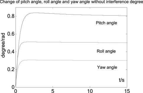
FIGURE 6. Changes in the pitch, roll, and yaw angles without interference.
Next, to investigate the anti-jamming performance of the designed controller, we assumed pitch, roll, and yaw angles of 0.8°, 0.5°, and 0.3° respectively, and considered the following interference patterns:
Interference pattern 1: We assume that the UAV flight system is subject to external disturbances in the first 5 s, such as strong winds, which are added as a step signal with a magnitude of 0.1. After 5 s, the external disturbance ends and the third actuator breaks down. Then, at 10 s, the third actuator experiences a drift fault, drifting to
As shown in Figure 7, before the initial 5 s run, we added a step signal with a magnitude of 0.1 to represent an external disturbance in the system; the system will adjust with short dynamic regulation of the robust adaptive fault-tolerant controller to a steady state. At 5 s, we chose the third actuator to break down, while a drift fault occurred at 10 s. The diagram shows that the system is asymptotically stable, with the adaptive fault-tolerant performance of the designed controller. The elevation, roll, and yaw angles can accurately achieve the desired values of the system, with almost no fluctuation curve, which indicates the good performance of the designed robust adaptive fault-tolerant controller in interference pattern 1(Wang et al., 2019).
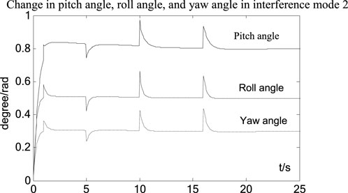
FIGURE 7. Interference pattern 1, with changes in the pitch, roll, and yaw angles.
Interference pattern 2: Like interference pattern 1, the flight system of the UAV is subjected to an external disturbance in the first 5 s, with an external disturbance amplitude step signal of 0.1. After 5 s, the third actuator experiences a failure and the time-varying partial failure expression is given by
As shown in Figure 8, before the initial 5 s run, we added a step signal with a magnitude of 0.1 to represent an external disturbance in the system; the system will adjust with short dynamic regulation of the robust adaptive fault-tolerant controller to a steady state. At 5 s, we chose the third actuator to break down, and a drift fault occurred at 10 s. The diagram shows that the system is asymptotically stable, with the adaptive fault-tolerant performance of the designed controller. The elevation, roll, and yaw angles can accurately achieve the desired value of the system, with almost no fluctuation curve, which indicates the good performance of the designed robust adaptive fault-tolerant controller in interference pattern 2 (Wang et al., 2021c).
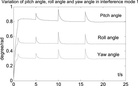
FIGURE 8. Interference pattern 2, with changes in the pitch, roll, and yaw angles.
In future power inspection processes, patrol UAVs will not only face physical hard-kill but also soft-kill interference, which will cause some losses. Therefore, we need to design a controller to communicate interference suppression, to ensure that the UAV can transmit information and coverage after experiencing communication interference.
First, data comparison and calculation allow evaluation of the information transmission capacity and coverage ability of the four-rotor UAVs. The evaluation results of each index are shown in Table 1 (Wang et al., 2022b).
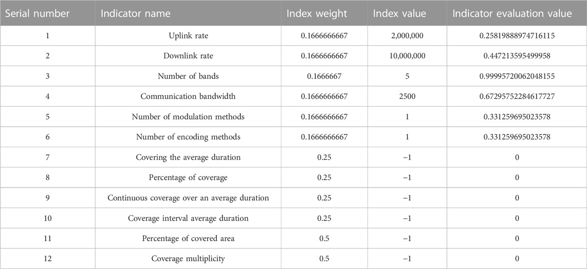
TABLE 1. Transmission capacity and coverage of the indicators of the assessment results.
In the next test, we first assessed the transmission capacity of the network and used the throughput to measure the performance.
Figure 11 shows that the throughput of the normal working phase of the system dynamically changes at 0–80 kb/s. After a jump, the system stabilizes at 10–90 kb/s. Compared to the previous process, performance is optimized. Thus, the robust fault-tolerant controller, for uncertain networks with stochastic time delays, showed good optimization performance and can guarantee stable signal transmission capability (Wang et al., 2022c).
Through the above bedding, we tested the UAV information transmission and coverage capacities. We first considered the ground transmission capacity between three UAVs and the BeiDou satellite. Transmission capacity refers to the uplink rate, downlink rate, uplink utilization, and downlink utilization of four indicators.
Figures 9, 10, and 12 show that after the UAV communication is disturbed, the optimal transmission path can be independently selected to ensure capable transmission of the signal, by adjusting the random delay fault-tolerant controller. Thus, the designed controller can reverse information and communication interference.
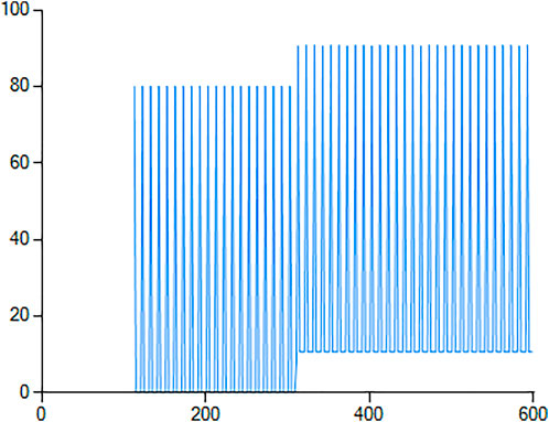
FIGURE 9. Network throughput graph.
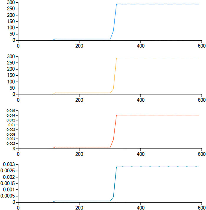
FIGURE 10. Link to ground transmission capability between UAV group 1 and the BeiDou satellite.
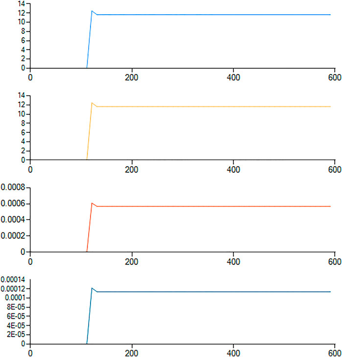
FIGURE 11. Link to ground transmission capability between UAV group 2 and the BeiDou satellite.
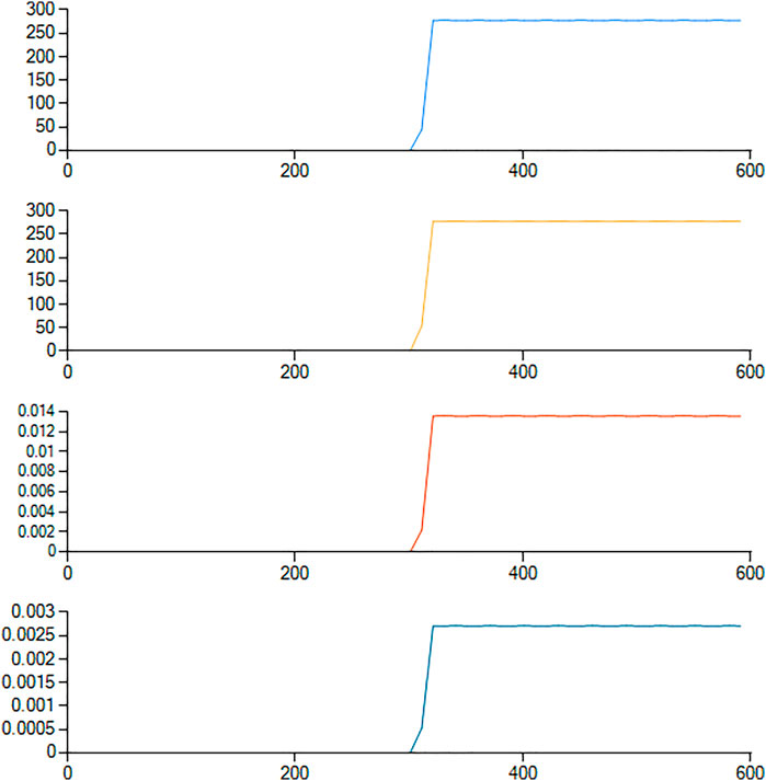
FIGURE 12. Link to ground transmission capability between UAV group 3 and the BeiDou satellite.
The results of the data analysis showed that the signal coverage of patrol UAVs under unknown information communication interference could be maintained at approximately 78.4%. The coverage performance of information communication is shown in Figure 13:
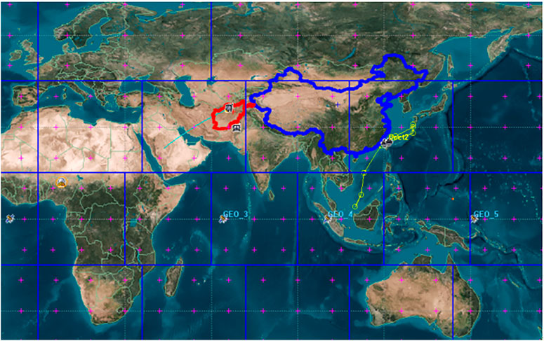
FIGURE 13. UAV group communication coverage performance.
Figure 13 shows that after the UAV communication is disturbed, the optimal transmission path can be independently selected to ensure capable transmission of the signal, by adjusting the random delay fault-tolerant controller. Moreover, the global coverage of the signal also showed good improvement (the blue area indicates that the signal is completely covered, while the ‘+’ symbol indicates good coverage performance). Hence, the designed controller demonstrated anti-interference ability in information communication.
We also tested the measurement error and compared it to the other results. To make the measurement more obvious, the error in the measurement was sufficiently large. After employing an extended Kalman filter (EKF) in the target tracking scenario, the error was minimized. Compared to the other algorithm, the EFK reduced the noise effect in target tracking. The EKF also effectively helped estimate the target position in the presence of noise and faults. This approach applied the EKF in parallel with fault tolerance algorithms to address the noise. Acceptable results, with a bias less than 5%, demonstrated the performance of the proposed scheme.
This project was used for line inspection of the Zhangjiakou Wind Power Test Base of the State Grid of China. The wind farm covers an area of 10 square kilometers and previously lacked wireless communication coverage. As the data transmission capacity of satellite communication is limited, we adopted a patrol method combining satellite navigation and positioning of the UAV cluster. The results of our experiments showed that the UAVs could transmit data and images, with a data transmission rate of over 50 Mbps. Moreover, the UAV group operated according to the set inspection track, with a deviation range of 2 m, ensuring normal operation of the wind farm.
7 Conclusion
This study established a mathematical model for electrical inspection, using a four-rotor unmanned aerial vehicle. According to the theory of robust adaptive fault-tolerant control, we designed a robust fault-tolerant controller for uncertain networks with random delays. We then performed a control simulation and a test simulation under the conditions of interruption, partial failure, and actuator drift fault. The simulation results showed that the aircraft gradually recovered to the steady-state after interference and failure. During operation, the pitch, roll, and yaw angles of the aircraft met the basic stability requirements and the aircraft stabilized rapidly. Overall, a precise control effect was achieved, and the aircraft demonstrated an anti-communication interference ability. Moreover, the information transfer capability and the global coverage capacity of the UAV also improved. Finally, the simulation results verified that the robust fault-tolerant controller was consistent with the Lyapunov asymptotic stability principle, and demonstrated validity, reliability, accuracy, and practicability.
Data availability statement
The original contributions presented in the study are included in the article/supplementary material, Further inquiries can be directed to the corresponding author.
Author contributions
All authors have made substantial, direct, and intellectual contributions to the work, and have approved its publication.
Funding
This paper was supported by a national grid key project: Key technology of scale engineering application of power battery for echelon utilization (project no. 52010119002F).
Conflict of interest
JS, JW, and YW are employed by State Grid Jibei Zhangjiakou Wind and Solar Energy Storage and Transportation New Energy Co, Ltd.
The remaining authors declare that the research was conducted in the absence of any commercial or financial relationships that could be construed as a potential conflict of interest.
Publisher’s note
All claims expressed in this article are solely those of the authors and do not necessarily represent those of their affiliated organizations, or those of the publisher, the editors, and the reviewers. Any product that may be evaluated in this article, or claim that may be made by its manufacturer, are not guaranteed or endorsed by the publisher.
References
Bi, K., Yu, J., Wang, Z., Zhu, W., and Wang, L. (2021). “A high-gain and broadband sector-shaped double-sided printed dipole array antenna for ad-hoc network nodes,” in 2021 IEEE MTT-S International Wireless Symposium (IWS), Nanjing, China, 23-26 May 2021 (IEEE), 1–3. doi:10.1109/IWS52775.2021.9499628
Bouadi, H., Bouchoucha, M., and Tadjine, M. (2008). Sliding mode control based on backstepping[J]. Int. J. Appl. Math. Comput. Sci. 4 (1), 12–17.
Fei, L. (2014). Four rotors helicopter adaptive fault-tolerant control algorithm of the attitude control system research[D]. Nanjing: NUAA.
Ioannou, P. A., and Sun, J. (1996). Robust adaptive control[M]. Upper Saddle River, NJ: Prentice-Hall, 90–134.
Khosravian, A., and Namvar, M. (2012). Rigid body attitude control using a single vector measurement and gyro. IEEE Trans. Autom. Contr. 57 (57), 1273–1279. doi:10.1109/tac.2011.2174663
Liu, L. L. (2009). Four-rotor modeling and control methods of research of flight simulator. Changsha: Central south university, 6–9.
Mokhtari, A., Benallegue, A., and Belaidi, A. (2005). Polynomial linear quadratic Gaussian and sliding mode observer for a quadrotor unmanned aerial vehicle[J]. J. Robotics Mechatronics 17 (4), 43–47.
Qing, Y., Song, H., Zhao, Q., and Shi, L. (2009). Four-rotor aircraft modeling, control, and simulation. Naval aeronautical engineering institute.
Tang, M. W., and Dai, L. H. (2013). Application of UAV in power line patrol[J]. China Electr. Power 46 (3), 35–38.
Wang, H. Y., Yuan, L. H., and Wu, B. (2009). MATLAB simulation and design of the control system[M]. Beijing: Higher education press.
Wang, Z., Yu, J., Lin, S., Dong, J., and Yu, Z. (2021). Distributed robust H∞ adaptive faultfault-tolerant control of amorphous and flat air-to-ground wireless self-organizing network system. Assem. Autom. 41 (6), 641–658. doi:10.1108/AA-04-2021-0041
Wang, Z., Yu, J., and Lin, S. (2021). “High-speed mobile real-time topology optimization of amorphous flattened air-to-ground wireless self-organizing network nodes based on dynamic planning,” in 2021 3rd international conference on electronics and communication, network and computer technology (ECNCT 2021) (SPIE Proceedings). doi:10.1117/12.2628545
Wang, Z., Yu, J., and Lin, S. (2022). Research on robust adaptive sliding film fault-tolerant control under nonlinear distortion of signal transmission in amorphous flat air-to-ground wireless ad-hoc network system. Assem. Autom. 42, 190–201. doi:10.1108/AA-04-2021-0045
Wang, Z., Yu, J., Wang, Z., and Lin, S. (2022). Bidirectional robust and fault-tolerant H∞ non-sensitive compensation filter controller based on amorphous flattened air-to-ground wireless self-assembly system. ISA Trans. doi:10.1016/j.isatra.2022.05.043
Wang, Z., Dong, J., Yu, J., Yu, Z., Lin, S., and Li, K. (2020). “The air-ground integrated MIMO cooperative relay beamforming wireless ad-hoc network technology research that based on maximum ratio combining,” in 2020 International Workshop on Electronic Communication and Artificial Intelligence (IWECAI), Shanghai, China, 12-14 June 2020 (IEEE), 11–19. doi:10.1109/IWECAI50956.2020.00010
Wang, Z. F., and Fu, X. F. (2017). LQR optimal control for quad-rotor aircraft[J]. Sens. world 3, 17–23.
Wang, Z. F., Yu, J. G., Bi, K., Lin, S. J., and Yu, Z. (2021). “A 2.4 GHz bidirectional power amplifier extending nodes distance of transmission to 14.8 km for amorphous flat air-to-ground wireless ad hoc network,” in Arabian journal for science and engineering (Spinger). doi:10.1007/s13369-021-06089-2
Wang, Z. F., Yu, J. G., Bi, K., Lin, S. J., and Yu, Z. (2022). Research on long-distance transmission of nodes in amorphous flat air-to-ground wireless ad-hoc network based on bidirectional relay beamforming. AD HOC Sens. Wirel. Netw. 51, 41–59.
Wang, Z. H., and Xiao-Ning, H. (2012). Research on transmission line inspection system based on four - rotor UAV[J]. China Electr. Power 10, 59–62.
Wang, Z., Yu, J., Lin, S., Dong, J., and Yu, Z. (2019). Distributed robust adaptive faultfault-tolerant mechanism for quadrotor UAV real-time wireless network systems with random delay and packet loss. IEEE Access 7, 134055–134062. doi:10.1109/ACCESS.2019.2936590
Xin-Zhe, Y. (2012). The four-rotor helicopter attitude system based on state observer active fault tolerant control research[D]. Nanjing: NUAA.
Yang, H. X., Yang, X. X., and Zhang, W. H. (2012). Distributed control of spacecraft formation using improved cyclic pursuit with beacon guidance. Appl. Mech. Mech. Eng. 138-139, 38–43. doi:10.4028/www.scientific.net/amm.138-139.38
Yong, Z. (2013). Four rotors aircraft fault-tolerant control system design and implementation [D]. Chengdu: UESTC.
Zhang, D. F., Wang, Z. Q., and Han, X. Dg (2014). Satisfactory Fault-Tolerant contro [M]. Beijing: Science press.
Zheng, J. X., Yuan, Z. H., and Yan-Ping, L. (2014). Adaptive fault-tolerant control theory method[M]. Beijing: Electronic industry press.
Keywords: power inspection UAV, information and communication interference, random time delay uncertain network, robust fault-tolerate control, extra-high voltage (EHV)
Citation: Shen J, Dong Wq, Wang Z-f, Wang J, Wang Y, Liu Hm and Li H (2023) Negotiation of the global grid inspection UAV with random delay uncertainty in an information communication network based on a robust fault tolerance mechanism. Front. Aerosp. Eng. 1:978261. doi: 10.3389/fpace.2022.978261
Received: 25 June 2022; Accepted: 15 November 2022;
Published: 12 January 2023.
Edited by:
Yuncheng Du, Clarkson University, United StatesReviewed by:
Liangyu Zhao, Beijing Institute of Technology, ChinaZhiguo Yan, Qilu University of Technology, China
Copyright © 2023 Shen, Dong, Wang, Wang, Wang, Liu and Li. This is an open-access article distributed under the terms of the Creative Commons Attribution License (CC BY). The use, distribution or reproduction in other forums is permitted, provided the original author(s) and the copyright owner(s) are credited and that the original publication in this journal is cited, in accordance with accepted academic practice. No use, distribution or reproduction is permitted which does not comply with these terms.
*Correspondence: Jie Shen, c2hlbmppZTc0QDE2My5jb20=
†These authors have contributed equally to this work and share first authorship