 Melody N. Mayle
 Rajnikant Sharma
- Department of Aerospace Engineering & Engineering Mechanics, College of Aerospace Engineering and Applied Science, University of Cincinnati, Cincinnati, OH, United States
A novel control technique for the platooning of aerial vehicles is here introduced, and its stability is analyzed. The controller applies a missile guidance law that was initially adapted for path-following and subsequently extended to platooning. The positions of all agents within a platoon employing this controller are estimated by exploiting cooperative localization, and these estimated positions are fed back into the controller. Using simulation, the agents within a platoon are demonstrated to follow their desired path and avoid collision, even in environments with intermittent Global Positioning System signals and limited sensing ranges.
1 Introduction
In the near future, the ways in which people and packages are transported in urban and rural areas are expected to resemble those previously envisioned only in science-fiction. Today, passengers and payloads typically fly across states in conventional, fixed-wing commercial airliners in an airspace miles above ground level and under the guidance of human traffic control operators. Soon, by contrast, crews and cargos will fly in smaller, electric vertical take-off and landing (eVToL) unmanned aerial systems (UASs) for shorter distances and at lower altitudes in airspaces that have yet to be defined. Local operations will vary between delivering food to households and air cabs, taxing individuals to restaurants; regional operations will vary between shipping blood samples to labs for testing and air ambulances, transferring patients to specialized hospitals for treatment.
To accommodate these emerging market demands that require an expanded aerial transportation system, the US Federal Aviation Administration (FAA) is undergoing what is recognized as one of the most ambitious infrastructure projects in United States history: modernizing the US National Airspace System (NAS), which is already the world’s busiest and most complex (Federal Aviation Administration, 2022). This project is known as the “Next-Generation Air Transportation System”, or “NextGen”. The FAA and the National Aeronautics and Space Administration (NASA), in collaboration with other public-private-academic partnerships, are establishing policies and developing technologies that will allow the safe and efficient integration of these additional UASs into the existing national airspace—or rather, its successor, the NextGen airspace. This expanded system of policies and technologies, which comprises both piloted and autonomous UASs arising from revolutionary eVToL technology and enabling the aerial transportation of humans and goods at low altitudes in populated metropolises, is known as Urban Air Mobility (UAM). This system, when considering rural areas and regions presently under-served by traditional aviation services, is referred to as Advanced Air Mobility (AAM). UAM, conceived first, was broadened into AAM, and UAM is now recognized as a subset of the latter (National Academies of Sciences, Engineering, and Medicine, 2020). A conceptual illustration of AAM operations is shown in Figure 1.
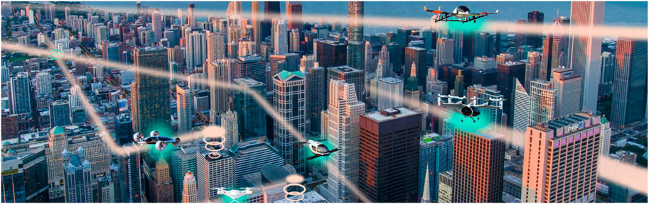
FIGURE 1. Conceptual illustration of Advanced Air Mobility (AAM) operations; photo credit: ANRA Technologies (2023).
Numerous challenges have been identified, potential solutions proposed, and further research suggested. Although several of the limitations are technological, concerns also exist regarding urban planning such as air rights, real estate development, public transportation, access inequalities, and community acceptance (Bauranov and Rakas 2021). Community acceptance considerations include affordability, privacy (and, equally important, the public’s perception of privacy), visual pollution, and auditory noise. Unlike traditional aviation services, UAM activities, by definition, will occur over densely populated cities. Consequently, UAM concepts, policies, and technologies must be centered around reducing the risk of property damage, bodily harm, and loss of life. When modernizing the airspace, both technological limitations and community acceptance influence the airspace structure.
With the competing objectives of maximizing both safety and efficiency, instituting the rules of engagement requires determining just how restricted the future airspace structure shall be: defined 1D lanes, free 3D space—both or neither? Agencies in the United States, Germany, France, Japan, and China have all proposed various solutions, along with companies such as Airbus, Amazon, Boeing, Embraer, and Uber (Bauranov and Rakas, 2021). To illustrate the different approaches, airspace structures and routing proposed by Airbus are shown in Figure 2. Free (Basic) Flight, Free Route, Corridors, and Fixed Route (depicted from left to right) are suggested for rural, suburban, airport, and metropolitan environments, respectively. An aircraft under Free (Basic) Flight rules may operate on any path and is solely responsible for maintaining separation between itself and other vehicles. An aircraft under Free Route rules may operate on any path only after receiving pre-authorization. An aircraft under Corridor rules may operate on any path, given that the path is within a pre-designated volume or corridor. Finally, an aircraft under Fixed Route rules may operate only on a pre-designated path or lane (Airbus, 2018).
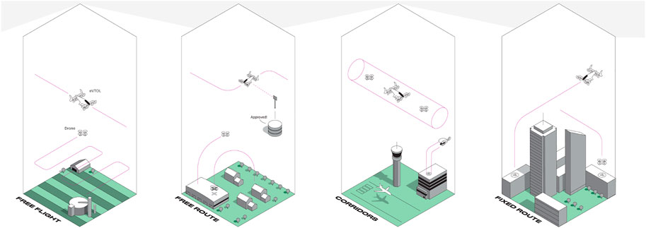
FIGURE 2. Airspace structures and routing proposed by Airbus (Airbus (2018)).
The conservative approach of defined lanes, largely supported by the public sector, arguably accommodates all UASs—even those without technological complexity—imposes stronger restrictions that protect residential areas, and encourages driver predictability. The liberal approach of free space, generally endorsed by the private sector, arguably promotes an increased number of UAS, facilitates shorter distances and faster times, alleviates air traffic controllers of increased workload, and maintains greater overall flexibility (Namuduri et al. (2021). The consensus on which structure actually minimizes the number of collisions remains unclear and likely depends on capacity. While free space distributes the traffic more evenly than defined lanes (Sunil et al., 2015) and potentially prevents any conflict, in the event of encounters with multiple UASs, the incident will result in gridlock or collision (Lowry, 2018), even with the most sophisticated collision-avoidance systems.
The European Commission’s Metropolis project investigated the impact of four different airspace structures on capacity by comparing safety and efficiency metrics in 2015 (Sunil et al.,2015). The airspace structures were designated Full Mix, Layers, Zones, and Tubes. Full Mix airspace is identical to Airbus’ Free (Basic) Flight. Layers airspace (imagine a slice of cake) is segmented into vertically stacked, horizontal planes at various altitudes. UASs operate at pre-designated heading angles within each plane. Zones airspace is similar to Layers airspace, except it considers the layout of a metropolitan area. Zones airspace (image a wagon wheel) is segmented into concentric circular zones surrounding the city, with radial zones connecting them. UAS operate clockwise in one circular zone and anti-clockwise in another, and inbound in one radial zone and outbound in another. Finally, Tubes airspace (imagine a graph with nodes and edges) is composed of multiple, connecting trajectories. Unlike any of the other airspaces, UASs operate along pre-defined paths with time constraints and with the expectation of being at a particular place at a specific time. Based on preliminary simulation results, Layers airspace was optimal for nominal conditions. Layers and Zones airspaces are illustrated in Figures 3A and B, respectively.
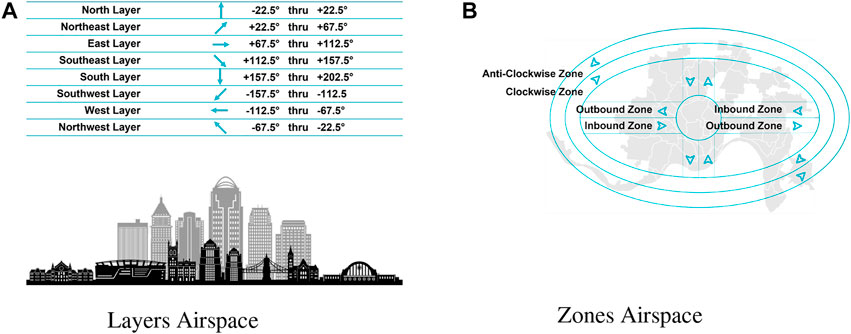
FIGURE 3. European Commission’s Metropolis airspaces. (A) Layers airspace. (B) Zones airspace.
Of the seven principles that govern the development of the UAM airspace, one is UASs’ resiliency to disruptions ranging from adverse weather to mechanical failure (Thipphavong et al.,(2018). One such disruption is the loss of Global Positioning System (GPS) signal, which is often degraded by buildings and infrastructure, particularly in populated metropolises. Despite its expected occurrence and significant impact, this risk has yet to be thoroughly assessed for any of the potential airspace structures. Therefore, the effect of the loss of GPS signal on the localization and guidance of UASs in an urban airspace is here explored.
To strengthen the robustness of the entire airspace system, the approach proposed here is platooning of UASs. Platooning enables a system of connected vehicles to operate as a coordinated unit with short separation distances. For ground vehicles, platooning allows for increased safety, greater vehicle capacity, improved traffic flow, reduced fuel consumption and emissions, and better rider experience (Martínez-Díaz et al., 2021). For aerial vehicles, platooning is versatile and suitable for operation in any of the aforementioned airspace structures. As shown later, platoons that exploit cooperative localization also produce enhanced position estimates, particularly in environments with degraded GPS.
The concept of platooning is not new, particularly for ground vehicles. Publications on platooning date back to the 1970s (Martínez-Díaz et al., 2021) and experiments to the late 1980s to early 1990s (Li et al., 2015; Martínez-Díaz et al., 2021) Martínez-Díaz et al. (2021) performed a comprehensive and systematic review, organizing and consolidating the existing information on platooning. Li et al. (2015) presented an overview of platoon control techniques that consider platoons as single networks composed of multiple dynamic systems. Both articles cite more than 70 different sources, reflecting the pervasive research on the topic.
While not specifically on platooning, Lewis et al. (2014) studied cooperative control and consensus of multi-agent dynamical systems interconnected by a communication network topology. However, inspired by Lewis et al. (2014), Porter (2017) developed a longitudinal controller for platooning ground vehicles that ensured convergence and collision avoidance. Platooning has also been examined for autonomous underwater vehicles (AUVs), which are subject to nonlinear uncertainties such as environmental disturbances due to ocean waves and currents. Shojaei and Chatraei (2021) employed a dynamic surface control technique that enabled a platoon of underactuated AUVs to track a trajectory while maintaining a desired separation distance and avoiding collisions. Platooning has only recently been examined for aerial vehicles and only a few publications are available. Dai and Nagahara (2023) conducted an experiment on a platoon of three, small drones indoors and demonstrated the effectiveness of their control technique. Using a camera and real-time object detection based on a deep learning model, the relative distance to the upstream drone was estimated and fed back into a proportional-derivative (PD) controller. The number and size of the eVToL UASs considered in our effort are on a much grander scale, with safety and the ability to localize in environments with degraded GPS being the priority. Therefore, an approach that applies a simplistic guidance law which produces both longitudinal and lateral commands is presumed to be most beneficial.
Consequently, a novel control technique for platooning aerial vehicles is introduced here and its stability is analyzed. The controller applies a missile guidance law that was initially adapted for path following and subsequently extended to platooning. The positions of all the agents within a platoon employing this controller are estimated by exploiting cooperative localization, and these estimated positions are fed back into the controller. Using simulation, the agents within a platoon are demonstrated as following their desired path and avoiding collision, even in environments with intermittent GPS signals and limited sensing ranges. Contributions include the following:
• aerial platoons exploiting cooperative localization and employing a novel control technique.
• controller with a modified velocity command and desired separation distance.
• stability analysis of the controller with supporting phase portraits.
• simulation results demonstrating the feasibility of this approach for any airspace structure.
The problem is mathematically formulated in Section 2 and includes an explanation of cooperative localization and the extended Kalman filter (EKF) and a description of the trajectory shaping guidance law. A method proposed for solving it—developing a controller for platooning UASs in airspaces with GPS signal degradation—is explained in Section 3. Simulation results, along with phase portraits that support the controller stability analysis, are presented in Section 4. Finally, future work is identified in Section 5.
2 Problem formulation
Consider a network of n electric vertical take-off and landing (eVToL) unmanned aerial systems (UASs). These UASs are agents within platoons operating in an airspace with an arbitrary structure. The n UASs are assigned to different platoons with varying numbers of agents, where Agent k of n total UASs is Agent i in Platoon j. Each UAS is assumed to be equipped with an altimeter that measures atmospheric static pressure, range-bearing sensors, such as radar, that measure distances and directions to other UASs, and radios that exchange data with the other UASs. Additionally, the leading agent (and only the leading agent) in each platoon is assumed to be equipped with GPS that measures inertial x, y positions and the heading angle. The agents with GPS are illustrated in turquoise in the fleet of platoons represented in Figure 4. All UASs are assumed to be able to hover or stop midair and to operate at constant altitudes. Using the data acquired by the onboard instrumentation, the joint state vector of all UASs is estimated by exploiting cooperative localization.
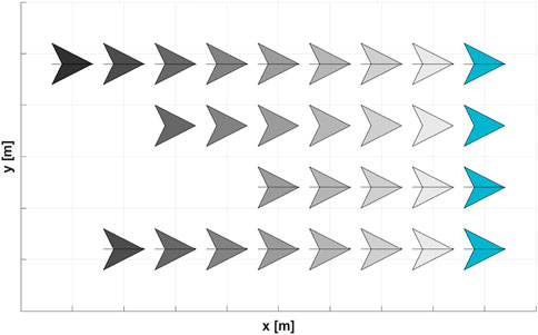
FIGURE 4. Fleet of platoons.
An explanation of cooperative localization and the EKF are provided in Subsection 2.1, along with the motion model and measurement models necessary for estimating the joint state vector. A description of the trajectory shaping guidance law is provided in Subsection 2.2, along with the velocity and lateral acceleration commands.
2.1 Cooperative localization and the extended Kalman filter (EKF)
One approach to estimating the joint state vector is to develop a centralized EKF. Given that all the eVToL UASs are assumed to be equipped with radios that exchange data with the other UASs, the EKF can exploit cooperative localization. Cooperative localization enables a network of agents to collectively estimate their positions, velocities, attitudes, and other states by exchanging measurement data. Cooperative localization is a common technique for improving the accuracy of position estimates, particularly in environments with degraded GPS signals. Related research efforts are diverse and ongoing. Sharma et al. (2012) investigated the relationship between a system’s relative position measurement graph (RPMG) and its nonlinear observability characteristics. Using graph and observability theories, they demonstrated that the positions of a system of cooperative vehicles can be estimated using only relative bearing angle measurements, provided that the system is connected to two distinct landmarks. Chakraborty et al. (2016), Chakraborty et al. (2019) developed a centralized cooperative technique to estimate the states of fixed-wing unmanned aerial vehicles (UAVs) by integrating measurement data acquired from a US Air Force test flight of 50 drones, and of multi-rotor UAVs using 3D bearing angle measurements and two landmarks. Mayle and Sharma (2021) developed a centralized cooperative technique to simultaneously estimate the states of fixed-wing UAVs, multi-rotor UAVs, and unmanned ground vehicles (UGVs) by adapting the prediction step of an EKF to accommodate the process equations for the motion of a non-homogeneous system.
Generally, an EKF is divided into two steps: prediction and update. In the prediction step, the process equations for motion are crudely integrated. In the update step, these predictions are corrected using measurements. Define a continuous, time-varying, nonlinear system with m states, p inputs, and q outputs (or measurements) by the state and output equations, respectively, as
where
The EKF prediction step is defined as
where
The EKF update step is defined as
where
The joint-state vector to be estimated comprises four states for each eVToL UAS such that
where vk and ωk are the commanded velocity and turn rate of Agent k, respectively, and ζv and ζω are the velocity and turn rate sensor noise, respectively. The commanded velocity and turn rate, which comprise the control input vector
Agent 1 in each Platoon j is assumed equipped with GPS that measures inertial x and y positions, and heading angle. GPS measurements for Agent k are defined as
for
where ρ and g are the air density and acceleration due to gravity, respectively, and ηP is the sensor noise for atmospheric static pressure. Finally, each agent is assumed to be equipped with range-bearing sensors, such as radar, that measure distances and directions to other agents. Radar measurements from Agent ki to Agent kj are defined as
where ηρ, ηα, and ηϵ are the sensor noise for range and azimuth and elevation bearing angles, respectively. These GPS, altimeter, and radar measurements are used in the update step of the EKF to correct the predictions.
2.2 Trajectory shaping guidance law
Missile guidance laws, historically applied to target interception, are now being adapted for path following. Missile guidance laws are recognized for their low computational demands and high accuracy and have been proven to be optimal and efficient (Ratnoo et al., 2015). Generally, they are simple and produce only two commands: a velocity for longitudinal control and a lateral acceleration applied perpendicularly to the velocity for directional control. When adapted for path following, an autonomous attacker follows a virtual target without the intent to intercept it. To track the path of the virtual target, the attacker applies a lateral acceleration command. To not evade the attacker, the virtual target applies a velocity command that varies as a function of the attacker velocity and their desired separation distance. In other terms, the lateral acceleration of the attacker depends on the virtual target, and the velocity of the virtual target depends on the attacker.
Assume the virtual target and attacker are point mass systems. The line joining these two points is the line-of-sight (LoS). The length of this line (or distance between the points) is designated rLoS; the angle between this line and a fixed (inertial) reference frame is designated ψLoS. An engagement between the virtual target and attacker is represented in Figure 5. The LoS distance and angle change with time. The attacker lateral acceleration commands are proportional to these rates of change; how exactly, depends on the guidance law.
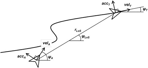
FIGURE 5. Engagement between the virtual target and attacker.
Ratnoo et al. (2015) evaluated the performance of two missile guidance laws—pure pursuit and trajectory shaping—for path following. They demonstrated that the trajectory shaping guidance law improved the position error and converged onto the desired path in half the time of the pure pursuit guidance law. For the trajectory shaping guidance law, the lateral acceleration of the attacker and the velocity of the virtual target are defined, respectively, as
where accA is the lateral acceleration of the attacker, velA and velT are the velocities of the attacker and virtual target, respectively, ψA and ψT are the heading angles of the attacker and virtual target, respectively, and rd is the desired separation distance between the attacker and virtual target.
While the lateral acceleration command for the trajectory shaping guidance law is appropriate for straight lines and curves with large radii, like the paths tracked by missiles, these commands are not suitable for curves with small radii, like the paths tracked by ground (or aerial) vehicles in urban environments (Erekson and Sharma, 2016). Therefore, Erekson and Sharma (2016) redefined the lateral acceleration command and demonstrated that the modified command achieved more accurate path following on curves with smaller radii. The modified lateral acceleration command does not assume small changes in heading angles and thus does not apply the small angle approximation—it does not assume sin(α) ≈ α. The lateral acceleration command, modified from Eq. 8, was redefined as
Subsequently, Erekson (2016) extended the trajectory shaping guidance law to the platooning of ground vehicles. When extended to platooning, Agent i is the virtual target for Agent i + 1 and is the attacker for Agent i − 1. In other terms, the lateral acceleration of Agent i depends on Agent i − 1, and the velocity of Agent i depends on Agent i + 1.
Two platoons are presented in Figure 6, where Agent 0 (in white) is the virtual target and Agent 1 (in turquoise) has GPS. The platoon in Figure 6A applies the lateral acceleration command introduced by Ratnoo et al. (2015); the platoon in Figure 6B applies the command proposed by Erekson and Sharma (2016). The platoon applying the lateral acceleration command proposed by Erekson and Sharma (2016) has better path convergence.
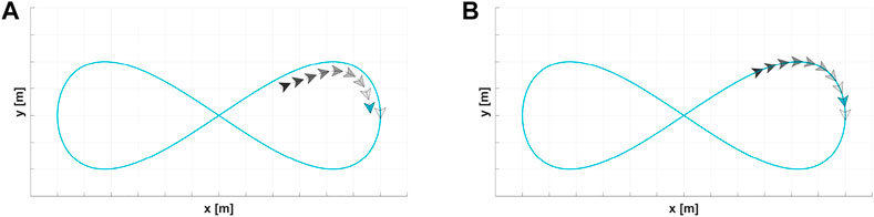
FIGURE 6. Trajectory shaping guidance law with different lateral acceleration commands. (A) Assumes small angles. (B) Does not assume small angles.
3 Methodology
Platoons are systems of connected vehicles that operate as coordinated units with small separation distances. Platooning allows for increased safety, greater vehicle capacity, improved traffic flow, reduced fuel consumption and emissions, and better rider experience. By exploiting cooperative localization, platooning also enhances position estimates in environments with degraded GPS. Applying the trajectory shaping guidance law proposed by Erekson (2016) and exploiting cooperative localization, a single platoon of up to nine agents follows figure 8’s path 1,200 m in the x-direction and 400 m in the y. The platoon operates at 30 m/s with an entrail separation distance of 50 m. Each agent is equipped with radar and radios, both with a 55-m sensing range, to measure and exchange positions and heading angles with its nearest agent(s). The leading agent (and only the leading agent) in the platoon is also equipped with GPS. The GPS signal availability varies from one sample per second to one sample per 120 s (2 min). The maximum covariance, or uncertainty of the position estimates, as a function of the time without a GPS signal for platoons with up to nine agents is provided in Figure 7.
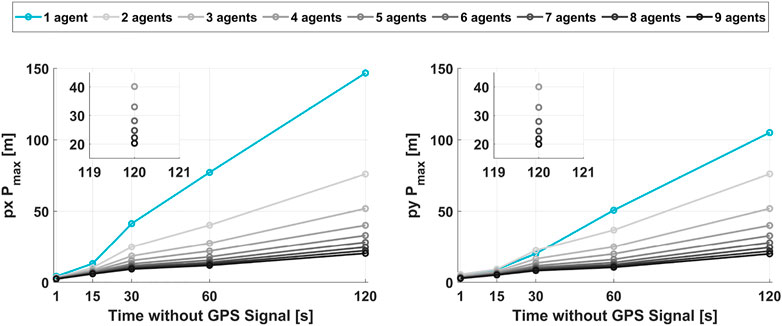
FIGURE 7. Maximum covariance Pmax -vs- time without a GPS signal.
From these preliminary results, the uncertainty in the position estimates is preserved by increasing the number of agents in the platoon. For a continuous GPS signal (one sample per second), the covariance is reduced by only a few meters with an increase in the number of agents in the platoon. However, the covariance is reduced exponentially for the intermittent GPS signals. Thus, for a single agent without a GPS signal for 2 min, the covariance in the x-direction is 150 m; for nine agents, the same covariance is 20 m despite no additional GPS measurements. Although a 20-m uncertainty is not insignificant, it is fortunately not likely to result in a collision with other agents in a platoon whose separation distance is 55 m, or more than twice 20 m. Given these observations, platooning is further explored by introducing a novel control technique in Subsection 3.1 and analyzing its stability in Subsection 3.2.
3.1 Controller
In the trajectory shaping guidance laws by Ratnoo et al. (2015), Erekson and Sharma (2016), and Erekson (2016), the lateral acceleration of Agent i depends on Agent i − 1, and the velocity of Agent i depends on Agent i + 1. The velocity information propagates upstream, and the leading vehicles adjust their velocities to accommodate the vehicles following, as illustrated in Figure 8A. While this information flow topology is appropriate for a single attacker and virtual target, it is not suitable for a platoon with multiple agents. Therefore, we redefine the velocity command and propose that the velocity information propagate downstream, and the following vehicles adjust their velocities to accommodate the leading vehicles, as illustrated in Figure 8B. In other terms, both the lateral acceleration and the velocity of Agent i depend on Agent i − 1. In the event that a leading agent slows down or stops, this modification prevents a collision with other agents in the platoon. The velocity command, modified from Eq. 9, is redefined as
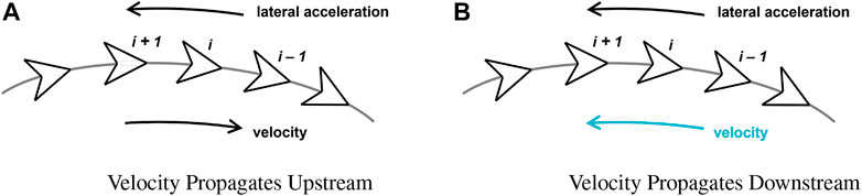
FIGURE 8. Information flow topology of platoons applying the trajectory shaping guidance law. (A) Velocity propagates upstream. (B) Velocity propagates downstream.
Additionally, in the methods by Ratnoo et al. (2015), Erekson and Sharma (2016), and Erekson (2016), the desired separation distance is fixed. In our approach, it is dynamic and a function of the position estimates uncertainty of the agents in the platoon. The separation distance increases proportionally with the covariance yet is bounded by the sensing range. In the event that the GPS signal is degraded or intermittent for an extended period of time, this modification also potentially prevents a collision with other agents in the platoon. The dynamic desired separation distance is defined as
where P is the actual uncertainty (maximum covariance between the px and py position estimates), Pmax and Pmin are the expected maximum and minimum uncertainties and respectively and predicted from preliminary results such as those provided in Figure 7, rd_max < srmax is the maximum separation distance and less than the maximum sensing range, rd_min is the minimal separation distance, or what is the nominal fixed desired separation distance in the methods of Ratnoo et al. (2015), Erekson and Sharma (2016), and Erekson (2016).
Algorithm 1. Platooning Applying Trajectory Shaping Guidance Law.
1: for j = 1: no_of_Platoons do
2: P = max
3:
4:
5: vel_d = desired_velocity(j)
//Commands for Leading Agent
6: vel (1, j) = vel_d
7: omega (1, j) = desired_omega(j)
8:
//Commands for Following Agent(s)
9: for i = 2: no_of_Agents(j) do
10: dpx = px (i − 1, j) − px (i, j)
11: dpy = py (i − 1, j) − py (i, j)
12: dpz = pz (i − 1, j) − pz (i, j)
13:
14:
15:
16: if vel (i, j) > max_velocity then
17: vel (i, j) = max_velocity
18: end if
19:
20:
21:
22: end for
23: end for
To illustrate, the dynamic desired separation distance as a function of the covariance is provided in Figure 9. In the next section, the stability of the controller is analyzed. We demonstrate that the actual separation distance of the agents converges to the desired separation distance of the agents near the system equilibrium point. Given that the system is stable, collisions are avoided, provided (a) the actual covariances are within the expected minimum and maximum covariances predicted from preliminary results, and (b) the estimates are consistent, that is, are bounded by the actual covariances.
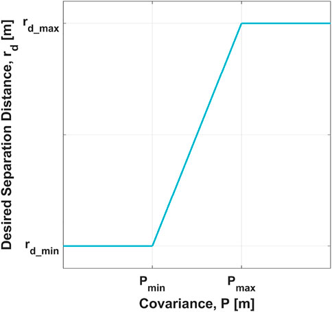
FIGURE 9. Desired separation distance rd -vs- covariance P.
A complete pseudo-algorithm for platooning by applying the trajectory shaping guidance law is provided previously. Line 4 is shows the dynamic separation distance that we introduce, line 15 is the velocity command that we redefined, line 19 is the lateral acceleration command that Erekson and Sharma (2016) redefined. The velocity and turn rate, the latter of which is a function of both the lateral acceleration and velocity, comprise the control input vector to the system defined in Eq. 4. The control input vector is defined as
3.2 Stability analysis
To analyze the stability of the platoon, the state vector and kinematic equations of motion are first redefined in a relative coordinate frame to better represent the influence of one agent on another, and the commands from the control input vector are substituted into the equations of motion. The system is then linearized and evaluated at its equilibrium point, or the conditions at which the equations of motion are all equal to zero. Finally, the eigenvalues of the linearized system are calculated, and the real parts are inspected for their signs. From Theorem 1, if the real parts of all the eigenvalues are negative, then the system is considered stable near its equilibrium point (Hespanha, 2009). Given the complexity of calculating the eigenvalues analytically, they are computed numerically using the conditions of the platoon that produced the preliminary results shown in Figure 7.
Theorem 1. Eigenvalue Condition.A continuous, time-invariant, linear system is stable if and only if all eigenvalues of its system matrix have strictly negative real parts.
The state vector to be analyzed is defined as
where v1 and ω1 are defined by the user, and vk and ωk comprise the control input vector:
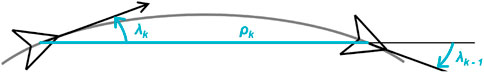
FIGURE 10. Engagement between two agents in a relative coordinate frame.
The platoon reaches a state of equilibrium when the range between agents is the desired separation distance ρk,eq = rd and when the relative heading angles of agents are those which are necessary to achieve the desired turn rate and opposite λk−1,eq = −λk,eq = f (ωd). This occurs when both (a) the velocity of all the agents is constant and equal the desired velocity vd, or that of the leading agent as defined by the user, and (b) the turn rate of all the agents is constant and equal to the desired turn rate ωd, or that of the leading agent as defined by the user. Mathematically stated:
Define the linearized system by
where
Define the characteristic polynomial of A by
Finally, let the desired velocity vd = 30 m/s, the desired entrail separation distance rd = 50 m, and the relative heading angle λeq = 15° at equilibrium (arbitrarily assigned, given the path is a figure-8). Using these values, the real parts of the eigenvalues s determined from Eq. 19 are all negative. Thus, the system is stable at the equilibrium point defined.
4 Results
To support the analytical stability analysis performed in Subsection 3.2, a phase portrait is provided in Subsection 4.1. To illustrate the effects of the modified velocity command and dynamic desired separation distance, platoons employing our approach are compared to those employing the methods by Erekson (2016) in Subsection 4.2. Finally, to demonstrate the feasibility of this approach for any airspace structure, multiple platoons operating in both the Layers and Zones airspace structures are provided in Subsection 4.3. Animations of the figures with platoons presented throughout this article are available online at the following link:
4.1 Phase portraits supporting stability analysis
A phase portrait of the control technique analyzed in Subsection 3.2 is provided in Figure 11. The small gray vectors represent the kinematics of the relative states at discrete points, and the turquoise curves represent six different trajectories. The initial conditions of the trajectories are arbitrarily selected and a turn rate ωd = 3 deg/s is assigned, along with the desired velocity vd = 30 m/s and entrail separation distance rd = 50 m from the previous analysis. Despite having unique initial conditions, all six trajectories have the same terminal condition, as illustrated by the black point, equal to the state of equilibrium. The platoon reaches a state of equilibrium when the range between agents is the desired separation distance ρk,eq = rd and when the relative heading angles of agents are those which are necessary to achieve the desired turn rate and opposite λk−1,eq = −λk,eq = f (ωd). For the selected initial conditions and assigned parameters, the equilibrium point is
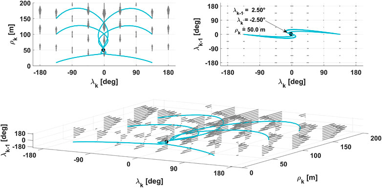
FIGURE 11. Phase portrait of the control technique.
4.2 Modifications to velocity command and desired separation distance
Two platoons are presented in Figure 12. The platoon in Figure 12A applies the velocity command with the information propagating upstream, as employed by Erekson (2016). The platoon in Figure 12B applies the velocity command with the information propagating downstream, as proposed herein. The platoon applying our velocity command does not result in a collision when a leading agent stops. Two other platoons are presented in Figure 13. The platoon in Figure 13A has a fixed desired separation distance, as employed by Erekson (2016). The platoon in Figure 13B has a dynamic distance. The platoon with the dynamic distance has more separation between the agents, provided that the covariance of the estimated positions is greater.
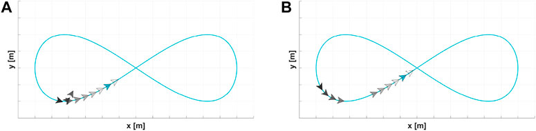
FIGURE 12. Trajectory shaping guidance law with different velocity commands. (A) Velocity info flows upstream. (B) Velocity info flows downstream.
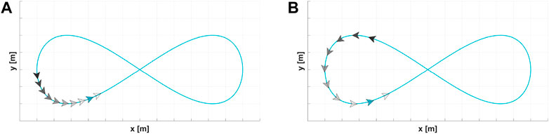
FIGURE 13. Trajectory shaping guidance law with different desired separation distances. (A) Fixed separation distance. (B) Dynamic separation distance.
4.3 Platoons operating in the Layers and Zones airspace structures
Consider a network of n electric vertical take-off and landing (eVToL) unmanned aerial systems (UASs) or agents within platoons in an airspace with the architecture fundamentals envisioned by NASA Ames Research Center’s Lowry (2018) as listed as follows:
• 1,000,000 agents within a 100-km×100-km area, or 100 agents in 1 km2
(based on automobile traffic statistics from the San Francisco Bay Area, CA)
• altitude between 500 ft. and 4,000 ft., or 150 m and 1,220 m
• aircraft speed of 100 km/h
(based on that of the Volocopter, the only UAM vehicle certified as of 2018)
• entrail separation of 10 s (or 300 m at 30 m/s) for agents NOT in platoons
• lateral separation of 150 ft. or 50 m
• vertical separation of 500 ft. or 150 m
Influenced by these fundamentals, 12 platoons with the number of agents varying between 8, 9, and 10 for two different airspace structures are illustrated. All the platoons employ the control technique introduced herein and exploit cooperative localization. Each agent is equipped with radar and radios, both with a 105-m sensing range, to measure and exchange positions and heading angles with its nearest agent(s). The leading agent (and only the leading agent) in each platoon is also equipped with GPS. The GPS signal availability is one sample per 30 s. In Figure 14, the platoons operate in the Layers airspace structure. Layers airspace is segmented into vertically stacked, horizontal planes at various altitudes. UASs operate at pre-designated heading angles within each plane. The estimated root-mean-square errors (RMSE) and covariances of the agents in the turquoise platoon are provided in Figure 15. Despite Agent 1 having only one GPS sample per 30 s, the RMSE of each agent is less than 2 m in the x and y positions. The covariance is less in the x position than in the y position as the agents in the turquoise platoon operate along the x direction. In Figure 16, the platoons operate in the Zones airspace structure. Zones airspace is segmented into concentric circular zones surrounding the city, with radial zones connecting them. UASs operate clockwise in one circular zone and anti-clockwise in another; inbound in one radial zone and outbound in another. The estimated RMSE and covariances of the agents in the turquoise platoon are provided in Figure 17. Again, the RMSE of each agent is less than 2 m in the x and y positions. The covariance in the x and y positions are similar as the agents in the turquoise platoon operate comparably along both the x and y directions.
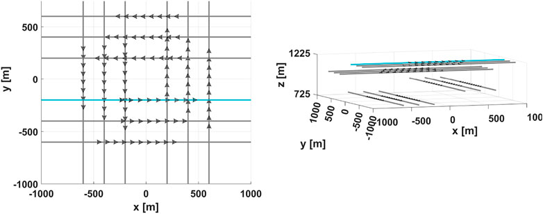
FIGURE 14. Platoons operating in the Layers airspace structure.
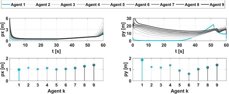
FIGURE 15. Estimated RMSE and covariances of a platoon operating in the Layers airspace structure.
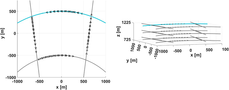
FIGURE 16. Platoons operating in the Zones airspace structure.
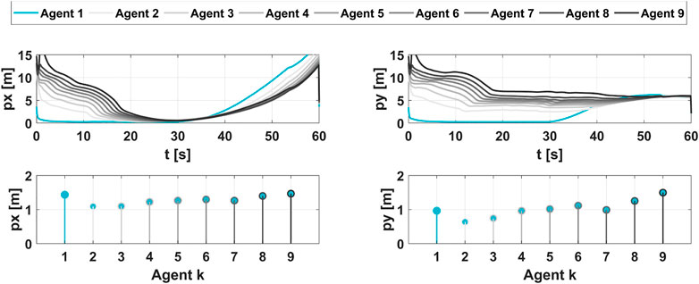
FIGURE 17. Estimated RMSE and covariances of a platoon operating in the Zones airspace structure.
5 Conclusion
In the near future, the modalities by the ways in which people and packages are transported in urban and rural areas are expected to resemble those previously envisioned only in science-fiction. To accommodate emerging market demands that require an expanded aerial transportation system, the FAA and NASA, in collaboration with other public–private–academic partnerships, are establishing policies and developing technologies that will allow the safe and efficient integration of additional unmanned aerial systems (UASs) into the existing national airspace—or rather, its successor, the NextGen airspace. With the competing objectives of maximizing both safety and efficiency, the rules of engagement require determining just how restricted the future airspace structure shall be: defined 1D lanes, free 3D space both or neither? Of the seven principles that govern the development of Urban Air Mobility (UAM) airspace, one is UASs’ resiliency to disruptions, ranging from adverse weather to mechanical failure. One such disruption is the loss of GPS signal, which is often degraded by buildings and infrastructure, particularly in populated metropolises. Despite the expected occurrence and significant impact, this risk has yet to be thoroughly assessed for any of the potential airspace structures. Therefore, the effect that the loss of GPS signal has on the localization and guidance of UASs in an urban airspace is explored. To strengthen the robustness of the entire airspace system, the approach proposed here is the platooning of UASs. Platooning enables a system of connected vehicles to operate as a coordinated unit with short separation distances. For ground vehicles, platooning allows for increased safety, greater vehicle capacity, improved traffic flow, reduced fuel consumption and emissions, and better rider experience. For aerial vehicles, platooning is versatile and suitable for operation in any of the proposed airspace structures. Platoons that exploit cooperative localization also produce enhanced position estimates, particularly in environments with degraded GPS.
This study introduces a novel control technique for platooning aerial vehicles and analyzes its stability. The controller applies a missile guidance law that was initially adapted for path following and subsequently extended to platooning. In this control technique, both the velocity command and desired separation distance are modified. In the current methods, the velocity information propagates upstream and the leading vehicles adjust their velocities to accommodate the following vehicles. In the proposed approach, the velocity information propagates downstream and the vehicles following adjust their velocities to accommodate the leading vehicles. In the event that a leading agent slows downs or stops, this modification prevents a collision with other agents in the platoon. Additionally, in the current methods, the desired separation distance is fixed. In the proposed approach, it is dynamic and a function of the position estimates uncertainty of the agents in the platoon. The separation distance increases proportionally with the covariance yet is bounded by the sensing range. In the event that the GPS signal is degraded or intermittent for an extended period, this modification potentially prevents a collision with other agents in the platoon. The positions of all the agents within a platoon employing this controller are estimated by exploiting cooperative localization and these estimated positions are fed back into the controller. Using simulation, the agents within a platoon are demonstrated to follow their desired path and avoid collision, even in environments with intermittent GPS signals and limited sensing ranges.
To further demonstrate the robustness of the proposed control technique, future work includes performing a more thorough stability analysis that considers disturbances and other uncertainties using approaches such as those credited to Robert Stengel, Princeton University. Future work also includes extending this control technique to three dimensions and introducing a method for agents entering and exiting the platoon, further broadening operations in the various airspace structures. To further improve estimation accuracy while limiting resources and expenditure, future work includes investigating cooperation and interaction between multiple platoons. This can be achieved by determining the optimal trajectories or sequencing of platoons to maximize throughput, eliminating the need for sophisticated collision-avoidance technologies.
Data availability statement
The original contributions presented in the study are included in the article/Supplementary Material; further inquiries can be directed to the corresponding author.
Author contributions
Authors MM and RS collaboratively idealized and formulated the problem. MM implemented the simulations, produced the results, documented the findings, and with guidance from RS, performed the stability analysis. All authors contributed to the article and approved the submitted version.
Funding
The University of Cincinnati College of Engineering and Applied Science and in support of the Air Force Research Laboratory (AFRL) AFWERX Technology Directorate, funded this effort.
Conflict of interest
The authors declare that the research was conducted in the absence of any commercial or financial relationships that could be construed as a potential conflict of interest.
The author RJ declared that they were an editorial board member of Frontiers, at the time of submission. This had no impact on the peer review process and the final decision.
Publisher’s note
All claims expressed in this article are solely those of the authors and do not necessarily represent those of their affiliated organizations, or those of the publisher, the editors, and the reviewers. Any product that may be evaluated in this article, or claim that may be made by its manufacturer, is not guaranteed or endorsed by the publisher.
References
ANRA Technologies (2023). “ANRA technologies extends NASA advanced air mobility effort with national campaign sweep of project awards,” in Image is from the ANRA technologes. Available at: https://www.anratechnologies.com/home/news/anra-technologies-extends-nasa-advanced-air-mobility-effort-with-national-campaign-sweep-of-project-awards/.
Bauranov, A., and Rakas, J. (2021). Designing airspace for urban air mobility: A review of concepts and approaches. Prog. Aerosp. Sci. 125, 100726. doi:10.1016/j.paerosci.2021.100726
Beard, R. W., and McLain, T. W. (2012). Small unmanned aircraft: Theory and practice. Princeton, NJ: Princeton University Press. doi:10.5555/2462627
Chakraborty, A., Sharma, R., and Brink, K. (2019). “Cooperative localization for multi-rotor unmanned aerial vehicles (UAV),” in AIAA SciTech 2019 forum.
Chakraborty, A., Taylor, C., Sharma, R., and Brink, K. (2016). “Cooperative localization for fixed-wing unmanned aerial vehicles (UAV),” in IEEE/ION position, location, and navigation symposium (PLANS) (Savannah, GA, USA: IEEE), 106–117.
Dai, X., and Nagahara, M. (2023). Platooning control of drones with real-time deep learning object detection. Adv. Robot. 37, 220–225. doi:10.1080/01691864.2022.2119888
Erekson, I. T. (2016). Modified trajectory shaping guidance for autonomous path following control of platooning ground vehicles. Master’s thesis. Utah State University.
Erekson, I. T., and Sharma, R. (2016). Trajectory shaping guidance modification for convergence to curved paths of small radii.
Federal Aviation Administration (FAA) (2022). “Next generation air transportation system (NextGen),” in Information is from the FAA NextGen. Available at: https://www.faa.gov/nextgen.
Hespanha, J. P. (2009). Linear systems theory. Princeton, NJ: Princeton University Press. doi:10.2307/j.ctvc772kp
Lewis, F. L., Zhang, H., Hengster-Movric, K., and Das, A. (2014). Cooperative control of multi-agent systems: Optimal and adaptive design approaches. London: Springer. doi:10.1007/978-1-4471-5574-4
Li, S. E., Zheng, Y., Li, K., and Wang, J. (2015). “An overview of vehicular platoon control under the four-component framework,” in IEEE intelligent vehicles symposium (IV), 286–291.
Lowry, M. R. (2018). “Towards high-density urban air mobility,” in 2018 aviation technology, integration, and operations conference.
Martínez-Díaz, M., Al-Haddad, C., Soriguera, F., and Antoniou, C. (2021). “Platooning of connected automated vehicles on freeways: A bird’s eye view,” in XIV conference on transport engineering, CIT2021 (Transportation Research Procedia), 58, 479–486.
Mayle, M. N., and Sharma, R. (2021). “Cooperative localization in a GPS-limited environment using inter-vehicle range measurements for a system of multiple, non-homogeneous vehicles,” in AIAA SciTech 2021 forum.
Namuduri, K., Fiebig, U.-C., Matolak, D. W., Guvenc, I., Hari, K. V. S., and Määttänen, H.-L. (2021). Advanced air mobility: Research directions.
National Academies of Sciences, Engineering, and Medicine (2020). Advancing aerial mobility: A national blueprint. Washington, DC: The National Academies Press. doi:10.17226/25646
Porter, A. D. (2017). A study of consensus and collision avoidance in a platoon of vehicles using adaptive cruise control. Master’s thesis, University of Texas at Arlington.
Ratnoo, A., Hayoun, S. Y., Granot, A., and Shima, T. (2015). Path following using trajectory shaping guidance. J. Guid. Control, Dyn. 38, 106–116. doi:10.2514/1.G000300
Sharma, R., Beard, R. W., Taylor, C., and Quebe, S. (2012). Graph-based observability analysis of bearing-only cooperative localization. IEEE Trans. Robotics 28, 522–529. doi:10.1109/TRO.2011.2172699
Shojaei, K., and Chatraei, A. (2021). Robust platoon control of underactuated autonomous underwater vehicles subjected to nonlinearities, uncertainties, and range and angle constraints. Appl. Ocean Res. 110, 102594. doi:10.1016/j.apor.2021.102594
Sunil, E., Hoekstra, J., Ellerbroek, J., Bussink, F., Nieuwenhuisen, D., Vidosavljevic, A., et al. (2015). “Metropolis: Relating airspace structure and capacity for extreme traffic densities,” in 11th USA/europe air traffic management research and development seminar (ATM2015).
Keywords: platooning, urban air mobility (UAM), advanced air mobility (AAM), airspace structure, trajectory shaping guidance law, cooperative localization
Citation: Mayle MN and Sharma R (2023) Platooning in UAM airspace structures: applying trajectory shaping guidance law and exploiting cooperative localization. Front. Aerosp. Eng. 2:1176812. doi: 10.3389/fpace.2023.1176812
Received: 28 February 2023; Accepted: 16 May 2023;
Published: 12 June 2023.
Edited by:
Krishna Kalyanam, National Aeronautics and Space Administration, United StatesReviewed by:
Isaac Weintraub, Air Force Research Laboratory, United StatesKenny Chour, National Aeronautics and Space Administration, United States
Copyright © 2023 Mayle and Sharma. This is an open-access article distributed under the terms of the Creative Commons Attribution License (CC BY). The use, distribution or reproduction in other forums is permitted, provided the original author(s) and the copyright owner(s) are credited and that the original publication in this journal is cited, in accordance with accepted academic practice. No use, distribution or reproduction is permitted which does not comply with these terms.
*Correspondence: Melody N. Mayle, bWF5bGVtbkBtYWlsLnVjLmVkdQ==