 Sana Mazahir
 Sajid Ahmed
 Mohamed-Slim Alouini
- Department of Electrical and Computer Engineering, CEMSE Division, King Abdullah University of Science and Technology, Thuwal, Saudi Arabia
Concerns for spectrum congestion have spurred extensive research efforts on efficient spectrum management. Therefore, devising schemes for spectrum sharing between radar and wireless communication systems has become an important area of research. Joint communications-radar (JCR) systems are among the several approaches proposed to achieve this objective. In JCR systems, additional components and processes are added to an existing standardized communication platform to enable radar functions. Moreover, the communication waveform is used as an integrated JCR waveform, i.e., the same signal is used to communicate information to a receiver and to perform radar detection and estimation operations for a nearby target. The most common application of JCR systems is found in vehicle-to-vehicle (V2V) communication scenarios. In this article, an overview of the spectrum sharing methods is presented, with a focus on JCR systems in automotive and other applications. We first review the recent works on IEEE 802.11p- and IEEE 802.11ad-based radars. A basic description of the modeling of a JCR system and channels is presented, followed by discussions on the main components and processes employed in various JCR systems. We are mainly interested in how radar detection and estimation functions are performed in conjunction with the communication receiver functions with minimal alterations to the existing system. At the end of the paper, some performance trade-offs between the communication and radar sub-systems are also discussed.
1 Introduction and Motivation
1.1 Motivation
Owing to the increase in spectrum congestion, researchers are interested in devising new ways of using the spectrum more efficiently. In addition to the spectrum congestion problem, efforts in this direction have been further accelerated by the fact that, in recent years, radar has found a number of new applications in the consumer market, in addition to its conventional applications in military, aviation and meteorology. This includes applications in the automotive industry, such as adaptive cruise control, lane change assistance, cross-traffic alerts and obstacle avoidance in autonomous vehicles (Hassanien et al., 2019; Liu et al., 2019; Rahman et al., 2019). Radars are also finding new applications in health, such as in assisted living. At the same time, there is increased interest in vehicle-to-vehicle (V2V) communications and considerable efforts have been made to enable various safety functions, smart traffic application and to develop autonomous vehicles. Therefore, there are a number of applications that stand to benefit from the integration of radar and communication functions. Hence, spectrum sharing between radar and communication systems has attracted significant interest in recent years (Hassanien et al., 2019; Liu et al., 2019; Rahman et al., 2019).
1.2 Introduction and Classification
Several methods have been proposed in which a radar and a communication system can share a common spectrum (Liu et al., 2020). The methods can be broadly classified into three categories, namely 1) Cohabitation or Coexistence, 2) Cooperation and 3) Codesign. These methods will be briefly reviewed in Section 2. Among these methods, codesign is the most innovative and promising method, in which both communication and radar systems are implemented on the same platform. Hence, they share a number of hardware and functional components, including the RF front end and signal processing elements. The feasibility and desirability of codesign is discussed in Section 2. Codesign can be further classified into the following types: 1) Joint Radar-Communications (JRC) (Hassanien et al., 2019), which implements communication as a secondary function on a radar platform, 2) Joint Communication-Radar (JCR) (Kumari et al., 2017a), which implements secondary radar functions on a standardized communication system, and 3) a unified system that does not favor one or the other by default, rather adapts according to the application requirements (Petrov et al., 2019).
Although it is possible to design a unified system from scratch, however, most of the research in this area focuses on implementing either a JRC or a JCR system. One reason for this approach is the practical deployment perspective. Since both communication and radar are mature fields, both theoretically and practically, the design of an entirely new system is deemed less feasible. At the same time, a unified system is also expected to provide more scalability and better trade-offs among the two types of functions (Petrov et al., 2019). Nevertheless, very little work has been done in this direction. On the other hand, there have been significant developments in JRC system design, which have been surveyed in a number of recent articles (Liu et al., 2019; Hassanien et al., 2016; Hassanien et al., 2019). Therefore, in this article, we focus on reviewing the research on JCR systems. An overview of recent research in this area will be presented in Section 3.
1.3 Trends and Recent Developments
The overwhelming trend in JCR system design has been to remodel and restructure existing standardized communication platforms to implement an augmented radar system. This allows reuse of communication hardware and several signal processing components for the execution of radar functions. Studies have demonstrated that this can be accomplished with minimal alterations in the standardized system (Kihei et al., 2015; Kumari et al., 2017a). As a result, it is conceivable that this approach will potentially expedite the penetration of JCR technology into consumer markets, among which the automotive industry is the most prominent. Therefore, IEEE 802.11p, which is a V2V communication standard, was first developed into a JCR (Reichardt et al., 2012). In fact, most JCRs developed so far have been based on V2V communication platforms (Reichardt et al., 2012; Kihei et al., 2015; Daniels et al., 2017; Grossi et al., 2018; Kumari et al., 2019b; Petrov et al., 2019; Kumari et al., 2017a). An overview of the developments in IEEE 802.11p-based JCR system design is presented in Section 3.2. Later, the IEEE 802.11ad-based radar was developed, which uses millimeter-wave (mm-wave) technology. A review of research work on this IEEE 802.11ad-based radar is presented in Section 3.3. In addition to V2V JCR, other IEEE 802.11ad has also been developed for other applications, such as vehicle-to-pedestrian (V2P) (Duggal et al., 2019) and vehicle-to-infrastructure (V2I) (Muns et al., 2019). A generic scanning radar was also implemented in (Grossi et al., 2018), which can be tailored for a variety of application.
1.4 Challenges and Feasibility
The design and implementation of JCR/JRC involve several challenges. In terms of practical implementation, there are certain disparities between radar and communication specifications. This is because, traditionally, the two systems have always been developed and deployed independently. For example, a mono-static radar requires a comparatively larger transmit power, as the signal has to traverse a two-way path, which means it experiences a greater path loss, in addition to losses due to scattering. Similarly, military radars operate in the ultra wideband (UWB) frequency bands, thus using a much larger bandwidth as compared to current communication systems (Hassanien et al., 2016). However, many applications have been identified in which these gaps are being bridged by emerging new technologies. For example, mm-wave communications are capable of providing much larger bandwidths, which are found to be suitable for implementing radar systems on vehicles (Kumari et al., 2015). In addition, due to the increasing demand of V2V communication applications and automotive radars, new signal processing methods are also being developed that are found to provide better trade-offs among the system parameters (Hassanien et al., 2016, 2019; Liu et al., 2019). Consequently, it has become feasible to integrate V2V, V2P and V2I communications with automotive radars.
In terms of the design of joint systems, the foremost challenge is an integrated waveform (Hassanien et al., 2016; Kumari et al., 2017a; Hassanien et al., 2019), i.e., the system should be able to perform both communication and radar functions by transmitting one waveform. Therefore, this integrated waveform should have the capability of embedding and transmitting information to a communication receiver while also having appropriate characteristics (e.g., ambiguity function) for detection and estimation of target parameters. It should be noted here that there has been considerable research on passive WiFi radars in the past (Berger et al., 2010; Chetty et al., 2011; Colone et al., 2012; Maechler et al., 2012; Ivashko et al., 2014). A passive radar is one that does not transmit any signal on its own, but rather relies on signals of opportunity to detect targets. This type of radar is a cost-effective solution in certain applications, like border security, where there are fewer expected targets and less crowding. However, it is limited in its capability because it cannot initiate the detection and ranging operation without relying on other nearby WiFi resources. In this article, we focus on the active JCR or JRC. In case of JCR/JRC, a combined communication transmitter/active radar transmits a waveform, which is received and decoded by a communication user to extract information, while its echo from a target is received back at the source where target parameters are estimated. In Section 4, we discuss the system and channel models that have been adopted in the literature to describe the JCR functions. In this survey, we mainly focus on the recent developments in JCR system.
1.5 IEEE 802.11p- and 802.11ad-Based JCRs
As mentioned earlier, most developments in JCR system design focus on either IEEE 802.11p- or IEEE 802.11ad-based platforms. The former employs an orthogonal frequency division multiplexing (OFDM) waveform, and therefore, OFDM-radar techniques have been extended to implement the JCR. Some prominent contributions toward the modeling and the augmented signal processing for radar functions on the IEEE 802.11p-based V2V communication platform are described in Section 5. In contrast, IEEE 802.11ad utilizes a single-carrier (SC) waveform occupying the mm-wave band. This is more promising for implementing the JCR due to the larger bandwidth. Moreover, the preamble of the IEEE 802.11ad frame is composed of Golay complementary sequences (GCS), which are shown to have a favorable ambiguity function for implementing the radar functions. In Section 6, we discuss the recent advances that leverage these characteristics of IEEE 802.11ad transmissions to implement an integrated waveform.
1.6 Performance
It has been found in many cases that the performances of communication and radar subsystems on a JCR platform conflict with each other. For example, in the case of IEEE 802.11ad-based JCR, the communication data rate is compromised in order to achieve a certain accuracy in velocity estimation (Kumari et al., 2019b). Another example is the requirement of extra bandwidth to achieve sufficient range resolution in the case of IEEE 802.11p-based JCR (Kihei et al., 2015; Daniels et al., 2017). Therefore, it is important to analyze the relationships between the performances of the two subsystems. Some performance metrics are discussed in Section 6. Moreover, in order to improve the radar’s performance, certain alterations to the standards have also been proposed in more recent works (Kumari et al., 2018a; Kumari et al., 2019a; Kumari et al., 2019b). This may somewhat undermine the suitability of building JCRs on standardized platforms. Nevertheless, these approaches yield important insights into the problem that may help in building an enhanced unified system. These approaches are briefly discussed in Section 6. Finally, some concluding remarks about the current research and future prospects in this field are presented in Section 7.
2 Methods of Spectrum Sharing
Traditionally, communication and radar systems have been designed separately and independently, using different design methods and theoretical frameworks. They have also been allocated different frequency bands as well. Furthermore, in the past, radars were mostly used for military applications, whereas communication devices have a huge market in the consumer industry.
Table 1 shows a comparison of the radar and communication system specifications and functional blocks. From the general structure of the radar and communication transceivers, it is easy to see that the systems share many common elements. However, there are many differences, including bandwidth, waveforms, performance criteria and applications.
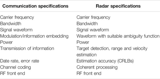
TABLE 1. A comparison of radar and communication system specifications.
Traditional radars occupy wider bandwidths compared to a communication user. Radar requires a larger bandwidth for satisfactory range resolution. However, recently the difference between the communication and radar domains is being mitigated with the emergence of mm-wave communications. Since the mm-waves have high frequencies and short wavelengths (1–10 mm), limited space can accommodate a large number of antennas, which enables beamforming.
Another important development that renders the joint system design feasible is the emergence of numerous new applications of radar in the consumer market. V2V communication has emerged as an important domain, and it is desirable to equip vehicles with both communication and radar modules for implementing several safety and traffic management function. Moreover, radars have also found applications in health applications and assisted living as well. In such applications, it is also desirable to equip the same devices with both radar and communication functions.
The methods of spectrum sharing explored in the literature can be classified into three types (Liu et al., 2019), namely cohabitation, cooperation and codesign. The main concepts governing these methods are illustrated in Figure 1. It should be noted here that the terms coexistence, cohabitation and cooperation are sometimes used interchangeably in the literature. Nevertheless, based on the working principle, the following three categories can be identified.
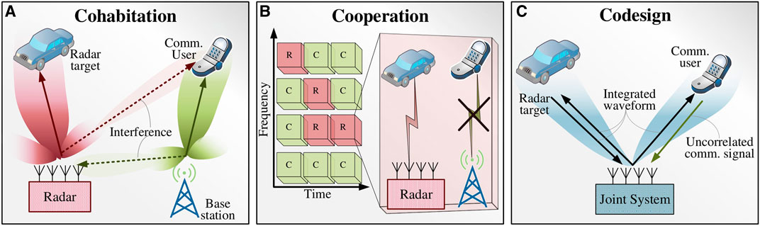
FIGURE 1. Spectrum sharing via (A) Cohabitation, (B) Cooperation and, (C) Codesign.
2.1 Cohabitation
The main idea is depicted in Figure 1A. In this method, radar and communication systems access the same frequency band simultaneously and in the same area of coverage. Each signal acts as an interferer for the other system. Normally, this would results in an intolerable increase in the signal-to-interference ratio (SIR) for both systems. However, the radar and communication systems cooperatively exchange information that helps them to keep this interference within tolerable limits. Techniques include implementing such cohabitation by joint power allocation optimized with constraints on quality-of-service (QoS) requirements for both the systems (Wang and Li, 2019) and successive interference cancellation at the receiver (Liu et al., 2019; Tian et al., 2019). Obviously, the drawback is that mutual interference and consequent degradation in both systems’ performances are inevitable. Moreover, since radar has to transmit more power, it becomes challenging for the communication receiver to mitigate the interference from the radar transmitter. Similarly, the echo signals from the target are of low power, which makes it challenging for the radar receiver to detect them in the presence of interference from the communication transmitter. This type of technique may be suitable in certain large-scale radar systems, like meteorological radars; however, they are not suitable for consumer products.
2.2 Cooperation
The main idea of cooperation is depicted in Figure 1B. This method employs an opportunistic spectrum access approach. In cooperation, one of the system is considered as primary user (PU) while the other as a secondary user (SU). Whenever PU is not using the channel, the SU can access it (Liu et al., 2019). Essentially, cognitive radios and cognitive radars come together in a combined network. This is simple to implement; however, this is not the most efficient method for spectrum sharing.
2.3 Codesign
The basic idea of codesign, as illustrated in Figure 1C, is to design an integrated waveform and a signal processing strategy to jointly handle the communication and radar functions on one hardware platform. This is the most innovative and promising approach toward spectrum sharing. In recent years, this problem has been approached by both radar and communication researchers. Both radar-centric (JRC) (Hassanien et al., 2016) and communication-centric(JCR) (Kumari et al., 2017a) solutions have been developed. It has also been proposed to design a completely new system with radar and communication subsystems in such a way that the system adapts according to requirements, without favoring one or the other by default (Petrov et al., 2019); however, there is very limited work done in this direction. The concept of an integrated waveform will be further discussed in Section 3.1. Since the focus of this article is the JCR system design, the use of IEEE 802.11p and IEEE 802.11ad waveforms as integrated JCR waveforms and their processing for the combined communication and radar receiver will be explained in Sections 5and6, respectively.
The codesign offers the most flexibility and cost-effectiveness compared to other approaches. A number of approaches have been proposed (Kumari et al., 2017a; Hassanien et al., 2019) that are capable of enabling additional functions without affecting the performance of the existing system, while also having the flexibility to make trade-offs when required. All of these developments make the codesign approach not only feasible but also desirable for future applications.
3 An Overview of Joint Communications-Radar Systems
A JCR system implements radar functions on a communication system platform. In order to accomplish this, it is required to identify the components of the communication platform that can be re-used for the radar and the components/processes that need to be modified, re-designed or integrated.
The reuse of communication systems for radar sensing is of particular interest in the case of V2V communication scenarios, especially considering the evolution of autonomous vehicles. The use of the IEEE 802.11p standard for radar sensing has been explored and developed in (Reichardt et al., 2012; Kihei et al., 2015) to enable collision avoidance. The IEEE 802.11p standard is a V2V physical layer protocol. It is adapted from the IEEE 802.11a standard for transmitting data in a geographic specific Dedicated Short Range Communication (DSRC) band using Orthogonal Frequency Division Multiplexing (OFDM) (Kihei et al., 2015). The use of this IEEE 802.11p will be further explained in Section 3.2.
More recently, due to the increased interest in millimeter wave communications, the IEEE 802.11ad standard has been developed into a JCR system (Kumari et al., 2015, 2017a; Grossi et al., 2018). This system exploits some properties of IEEE 802.11ad preamble to implement the radar functions. In (Rahman et al., 2019), a system-level framework for perceptive mobile networks is presented, which aims to integrate radar sensing functions into the entire network. System-level architecture, along with signal processing algorithms, are presented to implement these additional sensing functions on a unified platform. A brief survey of developments in this system is presented in Section 3.3.
3.1 Integrated Waveforms
In joint systems (JCR and JRC), the most important aspect is the design of a waveform that is capable of handling both radar and communication functions simultaneously. In radar systems, the waveform is mainly characterized by an ambiguity function, which determines the range and velocity resolution of the radar. Moreover, the duration of radar pulse determines the accuracy of the Doppler frequency estimation. On the contrary, communication waveform is designed by embedding and transmitting information to a user, which includes components for synchronization, channel estimation, frequency offset estimation and the data symbols.
The foremost challenge in a joint system implementing both communication and radar functions is the design of an integrated waveform. An integrated waveform is one that has an ambiguity function suitable for radar while also having the capability of performing communication functions, as depicted in Figure 1. For JRC systems, several radar waveforms have been reformulated to embed information in the radar pulses (Hassanien et al., 2019). For example, some coded phase shift keying (PSK) waveforms are suitable for radar function while also having the ability to carry information. Since the transmitted pulse is known to the radar, the radar functions remain largely unaffected, while the communication user demodulates the PSK signal to extract information. Since JRC is a radar-centric approach, in this case, well-known radar waveforms are utilized. On the contrary, JCR is a communications-centric method. Therefore in JCR systems, communication waveforms have been used to perform additional functions of detecting and ranging nearby targets (Kumari et al., 2017a). This is done by identifying those components of standard communication waveforms that have a favorable ambiguity functions. Since the use of an existing standard waveform is expected to accelerate the deployment and penetration of JCR systems in applications such as V2V communications, most efforts have been focused on exploiting IEEE 802.11 waveforms to implement radar functions. This includes OFDM-based waveforms in IEEE 802.11p (Daniels et al., 2017) and single-carrier, mm-wave signals in IEEE 802.11ad (Kumari et al., 2017a). For example, in IEEE 802.11ad-based radar (Kumari et al., 2017a), the frame preamble is used as a radar waveform. The preamble is composed of Golay codes, which are used by the communication receiver for synchronization, frequency offset estimation and channel estimation. These code sequences are found to also have a favorable ambiguity function for implementing radar functions as well. Another interesting approach has been proposed recently where a multi-carrier system allocates subcarriers to either communication or radar subsystems according to a mutual information (MI)-based objective function (Bică and Koivunen, 2019). In (Dokhanchi et al., 2019, 2018), phase modulated continuous wave (PMCW) and orthogonal frequency division multiple access (OFDMA) waveforms were proposed as integrated JCR/JRC waveforms. In these work, a bi-static system is proposed, which extends the sensing data to vehicles located at non-line-of-sight positions, thus providing spatial diversity to the target scene.
A number of recent survey articles have reviewed the JRC design in detail (Hassanien et al., 2016; Hassanien et al., 2019; Liu et al., 2019). Therefore, in this article, we focus on JCR systems in the next sections.
3.2 IEEE 802.11p-Based Radar
In (Reichardt et al., 2012), the system concept and feasibility of the IEEE 802.11p standard for JCR was demonstrated. IEEE 802.11p is a V2V communication standard, operating between 5.875 and 5.905 GHz. It employs OFDM, and thus, in order to be used as a radar, signal processing methods developed for OFDM-based radar have been used. Another earlier work (Braun et al., 2009) considered the design of a joint OFDM-based JCR waveform, however, in this work, no particular standard waveform was used. Nevertheless, this research identified some interesting OFDM parameter trade-offs for radar and communication subsystems. In (Kihei et al., 2015), the design of IEEE 802.11p-based JCR for a collision avoidance application is implemented. In this work, the waveform is treated as a multi-frequency continuous wave (MFCW) in the theoretical framework, and corresponding radar techniques are implemented to estimate the velocity and range of a vehicular threat. In (Vlastaras et al., 2013), the use of the same standard in a road side unit (RSU) installed at road intersections was proposed, where this unit acts as a radar and broadcasts range and velocity information of nearby traffic to the approaching cars, which are equipped with IEEE 802.11p-based communication units. In (Nguyen and Heath, 2017), mathematical modeling and signal processing algorithms for range and velocity estimation in multi-target scenarios were developed for IEEE 802.11p-based OFDM signaling. More recently, in (Daniels et al., 2017), the OFDM communications waveform, as found in IEEE 802.11a/g/p, was used as a forward collision vehicular radar. The forward collision vehicular radar aims to estimate the range of the closest target in front of the vehicle equipped with the radar. This is done by leveraging the frequency domain channel estimates obtained by the OFDM transceiver. Since the transmitter and receiver are collocated, obtaining the channel estimates is straightforward by using DFTs of the original and reflected signals.
The major limitation that has been identified with IEEE 802.11p-based radar is that even with the maximum allowed bandwidth, i.e., 20 MHz, it is not possible to achieve cm-level range and cm/s-level velocity estimation accuracy. Moreover, most radar systems prefer to employ constant-modulus waveforms, whereas OFDM signals suffer from a large peak-to-average power ratio (PAPR), which reduces the power efficiency of the system.
3.3 IEEE 802.11ad-Based Radar
The mm-wave IEEE 802.11ad standard was first investigated for JCR application in V2V communication platforms in (Kumari et al., 2015). It was identified that the preamble of IEEE 802.11ad frame, which is composed of Golay complementary sequences (GCS), has an ambiguity function similar to radar waveforms in the lower Doppler range. Hence, this part of waveform can be used for implementing radar functions. The concept was further developed in (Kumari et al., 2017a), where the communication and radar channels were modeled and the synchronization and frequency offset estimation outputs in the communication receiver were reused for range and velocity estimation, respectively. It was found in (Kumari et al., 2017a) that the velocity estimation accuracy was not satisfactory due to the short preamble length. Therefore, a virtual waveform was designed in (Kumari et al., 2019b). In this waveform, the preamble is non-uniformly placed in such a formulation that is said to capture the nuances of the sparse mm-wave communication and radar channels. This improves the velocity estimation at the expense of slight reduction in the data rate. Another limitation encountered in (Kumari et al., 2017a) was that the narrow analog beamforming of IEEE 802.11ad system did not provide a sufficient field-of-view (FoV) for the radar. A larger angular FoV allows the radar to detect more targets. Adaptive beamforming is proposed in (Kumari et al., 2018a) that provides a large FoV for the radar via sidelobe perturbation, while maintaining a narrow communication beam in the main lobe. This permits a trade-off between radar performance in the angular domain with the communication data rate. Further improvements were achieved by using a combined waveform-beamforming design in (Kumari et al., 2019a). In this work, the signal processing techniques are further developed to estimate the angles of arrival and departure (AoA/AoD) for the targets in the radar’s FoV. Recently, in (Grossi et al., 2018), an opportunistic radar in IEEE 802.11ad-based networks was proposed. In this case, the IEEE 802.11ad beam training protocol is used in a sector-level sweep (SLS) to detect the location and radial velocity of obstacles. As seen in (Kumari et al., 2017a), the velocity estimation in this case is also poor due to the short duration of the probing signal. More recently, a Doppler-resilient variant of GCS (Pezeshki et al., 2008) has been employed to improve the radar performance (Duggal et al., 2020), especially in case of multiple moving point targets or a single target with multiple point scatterers to extract micro-Doppler and micro-range features (Duggal et al., 2019).
4 System and Channel Models for JCR
In this section, we discuss the system model describing a V2V JCR application and the channel models adopted in various vehicular ranging applications. We discuss the modeling with long-range point targets and short-range extended targets with multiple point scatterers. It should be noted that similar analytical frameworks have been extended for V2P and V2I applications by modeling the radar signatures for respective target objects (Duggal et al., 2019; Muns et al., 2019).
4.1 System Model
We consider a V2V communication scenario where a source vehicle sends a standard communication waveform (e.g., IEEE 802.11ad frames) to a receiving vehicle and receives echoes of this waveform reflected from one or more target vehicles. These echoes are then used to estimate the range and velocity of targets. This scenario is depicted in Figure 2. The vehicles may be equipped with one or more transmit and receive antennas. In order to keep the model general, a multiple-antenna system is described, and the single antenna systems can be treated as a special case. Thus, the source vehicle is equipped with an
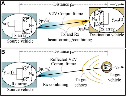
FIGURE 2. (A) One-way communication channel. (B) Two-way radar channel for a single-target vehicle.
The transmitted signal from the source vehicle is an integrated waveform, i.e., the same waveform transmits information to the receiving vehicle and acts as the transmitted signal of an active radar. The continuous-time, complex envelope of the waveform is written as
where
It is assumed that there is no obstacle between the source and destination and the target vehicles. In MIMO systems such as those supported in IEEE 802.11ad, single data stream with multiple transmit and receive antennas, with analog beamforming is employed. However, the beamforming equivalence in baseband can be established, so that the transmitted signal is written as:
where
A coherent processing interval (CPI) of T seconds is assumed. During this time, it is assumed that the channel remains invariant, the acceleration is small enough that constant velocity of the target vehicle can be assumed and the direction of target with respect to the source remains constant, so that
The received signal at the destination vehicle, i.e., the received communication signal after combining and discretizing, is written as follows:
where
where
The V2V JCR model depicted in Figure 2 is appropriate for long-range radar where far-field condition is sufficiently satisfied and a point target assumption is valid. On the other hand, when the target is close to the radar, the received signal is composed of multiple reflections from different parts of the same object (Duggal et al., 2019). An extended target model has been considered in (Duggal et al., 2019) and modifications to IEEE 802.11ad have been proposed to handle realistic radar signatures from pedestrians and vehicles. For a target with B point scatterers, the received signal is written as (Duggal et al., 2019):
where P is the number of IEEE 802.11ad packets constituting one CPI,
The IEEE 802.11ad preamble has good range resolution for static targets and for a single moving target in the far field. However, in case of multiple moving targets or single extended target with multiple point scatterers, the GCS has higher range sidelobes due to the Doppler shifts. Doppler-resilient variant of GCS has been used to improve the performance in this scenario (Duggal et al., 2019; Duggal et al., 2020; Pezeshki et al., 2008).
4.2 Communication Channel Model
The transmitted waveform is used as a communication signal as well as a radar signal. Therefore, the transmitted signal is received at two different receivers after going through two separate channels. As a communication signal, the waveform is transmitted from the source vehicle and is received at the destination, following a one-way communication channel. Depending on the operating frequency, the number of antennas and the type of automotive application, an appropriate communication channel model can be adopted. For instance, in (Kumari et al., 2017a), a V2V JCR is developed using the mm-wave IEEE 802.11ad waveform. Therefore, this channel is modeled as a dominant line-of-sight Rician fading channel, which is commonly adopted in V2V communication applications. Since the channel is assumed to be invariant within a CPI, for
where
where
4.3 Radar Channel Models
The same communication signal is reflected from a nearby target and the echo is received at the source vehicle, after going through a two-way radar channel. In the case of forward collision avoidance application for one primary target, such as those handled in (Kihei et al., 2015; Daniels et al., 2017), a two-path channel model has been adopted. Path 1 is the so-called direct path, which may result from antenna sidelobes or any leakage between the transmit and receive chains. Path 2 is the reflection from the target. The complex baseband equivalent of the impulse response of this forward collision radar channel is expressed as follows:
where α and β are path loss parameters of the two channel paths,
In the case of multiple targets, the radar channel is modeled more generally as a multi-path channel, such that each target contributes one round-trip reflection (Nguyen and Heath, 2017). The baseband equivalent and frequency response of this multi-target channel can be written as follows:
where
Although these models only incorporate single transmit and receive antennas, they can also be extended for MIMO radar. An example of a MIMO radar channel model can be found in (Kumari et al., 2017a), where a mm-wave V2V JCR is considered. This two-way mm-wave radar channel is modeled using the doubly selective (time- and frequency-selective) model, which is widely used in automotive radar. This channel is made up of a direct path scatter from the target and dominant multi-path spread-Doppler clutter. Non-dominant clutter is modeled as uncorrelated Gaussian noise. In the case of
where
5 JCR Using OFDM Waveform
JCRs employing OFDM waveform have been mainly developed using the standard IEEE 802.11p. In this case, an OFDM symbol is composed of 48 data-bearing subcarriers and four pilot symbols, while there are 12 null subcarriers to allow a guard band. The subcarrier spacing is
5.1 OFDM as MFCW Radar
In (Kihei et al., 2015), the IEEE 802.11p waveform is modeled as a multiple frequency continuous wave (MFCW) radar, and the corresponding theoretical framework has been extended for this waveform to implement a V2V collision avoidance application. The OFDM symbol is treated as an MFCW radar signal, such that the OFDM subcarriers represent N MFCW transmitters broadcasting a single frequency for the symbol duration
Figure 3 illustrates a summary of the signal processing operations. Since time delay translates into a phase rotation in the frequency domain, the range measurement is based on calculating the phase difference between two or more subcarriers. For example, consider two subcarriers with frequencies
where
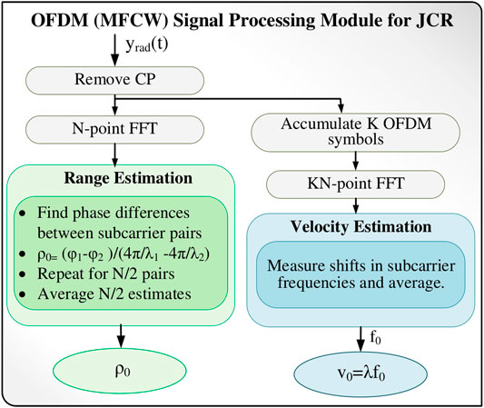
FIGURE 3. Signal processing for IEEE 802.11p JCR modeled as MFCW.
Using more than one pair of subcarriers, multiple such estimates can be obtained and averaged to improve the accuracy.
The Doppler shift in a continuous-wave (CW) radar is found by demodulating the carrier, followed by low-pass filtering and measuring the shift in carrier frequency. A similar approach has been used for OFDM in (Kihei et al., 2015), where frequency shifts in subcarriers are measured by comparing the spectrum of originally transmitted symbols and received symbols. Relative velocity is estimated as:
Similar to the range estimation, the Doppler shift can also be obtained for multiple subcarriers and averaged. However, The velocity resolution is limited by the frequency spacing
The work in (Kihei et al., 2015) successfully demonstrates the use of IEEE 802.11p communication waveform as a radar signal, however, this approach requires a bandwidth of 150 MHz for 1 m range resolution (Kihei et al., 2015; Daniels et al., 2017), whereas IEEE 802.11p operates at 5 MHz, 10 MHz and 20 MHz spectrum allocations. Moreover, particularly in case of the collision avoidance application, a maximum success rate of only 35.12% was observed (Kihei et al., 2015). In order to achieve a higher accuracy, channel estimation-based techniques are proposed in (Daniels et al., 2017; Nguyen and Heath, 2017).
5.2 Ranging via Channel Estimates
Meter-level range accuracy with 20 MHz bandwidth has been achieved by using the frequency domain channel estimates available on a IEEE 802.11p platform in (Daniels et al., 2017). The two-path channel model in Eq. 8 is adopted and it is assumed that the channel estimates are available as a result of the standard signal processing on an IEEE 802.11 platform. In frequency domain, the channel is expressed as follows:
Thus the channel estimates at mth subcarrier are represented as follows:
where
The delay parameter τ is estimated by a brute-force optimization algorithm that matches a sinusoid with the mean-normalized channel energy. The optimization problem is formulated as follows:
where
The Doppler shifts are not directly evaluated in this work. However, it is possible to apply differential computations on the ranging estimates obtained for many consecutive packets. Moreover, Doppler shift is also not incorporated in the channel model because its effect on the channel estimation is assumed to be negligibly small (Daniels et al., 2017). A summary of the signal processing strategy is depicted in Figure 4.
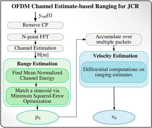
FIGURE 4. Channel estimation-based signal processing for IEEE 802.11p JCR for a single target.
Using this method, a range resolution of up to 1 m was achieved with 10 MHz bandwidth for a single target, while 20 MHz bandwidth was required in a two-target scenario.
5.3 Multi-Target Range and Doppler Processing
In (Nguyen and Heath, 2017), range and Doppler processing algorithms for an IEEE 802.11p-based JCR have been developed. This method is also based on frequency domain channel estimates available on an OFDM receiver. A multi-target scenario is considered and the channel model in Eq. 9 is adopted. In frequency domain, channel is represented as follows:
where K is the number of targets and
Assuming perfect synchronization and perfect channel estimation, the channel measurements at individual subcarriers and time slots can be written as (Nguyen and Heath, 2017):
where
A rotational invariance technique, i.e., the ESPRIT algorithm is utilized for resolving
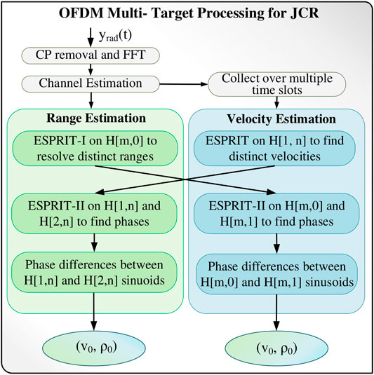
FIGURE 5. Multi-target delay and Doppler processing for IEEE 802.11p-based JCR.
In the first method,
The second method is dual of the first, i.e.,
The two methods can be used in conjunction to ensure maximum resolution. This is because if two targets are at the same range, they will not be resolved by the first method, while targets with similar velocities cannot be distinguished by the second method. Numerical results in (Nguyen and Heath, 2017) show that this method can achieve up to 0.2 m range accuracy and 0.02 m/s velocity resolution.
6 JCR Using SC Waveform
The single-carrier physical (SCPHY) packet of IEEE 802.11ad has been used to extract the radar target parameters in (Kumari et al., 2015; Kumari et al., 2017a). In this case, the radar target is the object in front of the transmitter after a directional link is established. Later in (Grossi et al., 2017a; Grossi et al., 2017b; Grossi et al., 2018), the control physical (CPHY) packet is used to implement a scanning radar during the sector level sweep (SLS) of IEEE 802.11ad transmission. In both cases, a preamble composed of Golay complementary sequences has been leveraged to implement the radar functions. In this section, the use of SC-PHY IEEE 802.11ad standard for the JCR system in a V2V application (Kumari et al., 2017a) is first explained, along with some enhancements proposed in (Kumari et al., 2019a; Kumari et al., 2019b).Some modifications to the Golay sequences in the SCPHY preamble have been proposed in (Duggal et al., 2020) to make it Doppler-resilient, which are then leveraged for micro-Doppler and micro-range detection for V2P application (Duggal et al., 2019). Moreover, we discuss the implementation of a scanning radar using CPHY preamble (Grossi et al., 2018), which is more generic in terms of application.
The main idea is to use the preamble of IEEE 802.11ad frame to implement the radar parameter estimation. This preamble is used for frame synchronization, frequency offset estimation and channel estimation on the communication platform, and is found to have properties that make the waveform suitable for implementing radar parameter estimation. We first describe the preamble and discuss its ambiguity function which makes it suitable for detection and ranging. This will be followed by signal processing techniques employed in the JCR. We conclude with a discussion on the performance trade-offs among the radar and communication functions.
In this case, the transmit waveform
6.1 The IEEE 802.11ad SC-PHY Preamble
Figure 6 shows the frame structure of IEEE 802.11ad waveform. This single carrier (SC) frame is composed of a short training field (STF), a channel estimation field (CEF), header, data blocks, and some optional fields reserved for beam training. The preamble of frame is used for implementing the radar functions.
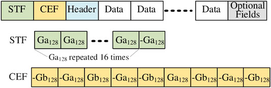
FIGURE 6. IEEE 802.11ad waveform and its preamble.
The preamble includes the STF and CEF, which are generated by Golay Complementary Sequences (GCS) of length 128. In Figure 6, these are denoted by Ga128 and Gb128. In the communication system, the STF is used for frame synchronization and frequency offset estimation, while the CEF is used for channel estimation. The STF and CEF fields, and the corresponding signal processing techniques used in the communication transceiver are leveraged and built upon to implement radar functions.
It is important to note here that the Golay sequences have been previously studied in radar waveform applications (Alejos et al., 2007; Pezeshki et al., 2008; Pace and Ng, 2010). The composite ambiguity function of GCS is studied in (Turyn, 1963) and found to be suitable for radar applications (Pezeshki et al., 2008). They are ideal for range imaging due to the perfect auto-correlation with negligible sidelobe along the zero-Doppler (Kumari et al., 2017a). However, the ambiguity function shows that the GCS are less tolerant to large Doppler shifts. In (Duggal et al., 2020), Doppler-resilient Golay complementary sequences (Pezeshki et al., 2008) have been employed to improve radar performance.
6.2 Preamble Processing Strategy
Figure 7 outlines the hierarchical signal processing strategy proposed in (Kumari et al., 2017a). In this scheme, the preamble is first processed in the communication receiver module, and then the frame detection, synchronization and frequency offset estimation outputs are used for target detection, range estimation and velocity estimation, respectively. The communication module processes each frame, while the radar processing is coherent over the CPI, which may consist of more than one frame. The main steps and basic principles of the detection and estimation techniques will be explained next. It should be noted that only single target scenarios are discussed for simplicity, however, mutiple-target scenario can be handled as well (Kumari et al., 2017a).
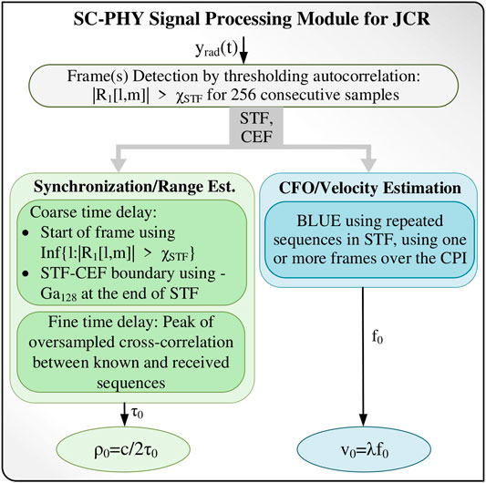
FIGURE 7. The preamble processing strategy.
On a communication receiver platform, first the frame is detected based on a preamble detection algorithm, which uses STF. Once the preamble is detected, carrier frequency offset (CFO) estimation is performed using STF by means of a best linear unbiased estimator (BLUE) and synchronization is performed by using both the STF and the CEF. Moreover, channel estimation is performed using the CEF.
In (Kumari et al., 2017a), it is shown that radar parameter estimation can either rely on communication module outputs, as shown in Figure 7, or conventional radar techniques can be used in parallel with the communication module. In this tutorial, only first strategy will be discussed, because the aim is to show how a communication platform can be reused for implementing the radar functions.
6.3 Frame and Target Detection
The preamble detection is based on a normalized auto-correlation of the received signal. The auto-correlation function is specifically constructed for the given structure of the STF. Since the STF contains repetition of GCS of length 128, the auto-correlation exhibits a plateau due to the periodicity within the STF. The presence of this plateau ensures robust detection, however, reduces the accuracy of the time synchronization from the STF (explained in next section). The lth normalized auto-correlation for mth frame, for the given STF of 128-length GCS, is found as follows:
The frame is detected when
6.4 Synchronization and Range Estimation
Using the start of the frame, a coarse time-delay estimate, with a precision equal to the symbol period
where
The second coarse delay estimate
For fine time delay estimate, two methods are proposed in (Kumari et al., 2017a). One estimate
Oversampling by a factor of 8 is used to obtain precise peak location. The channel estimation-based method is preferable for multiple-target scenarios because of the auto-correlation plateau, whereas a single target can be conveniently detected by using the peak of cross-correlation.
Once the coarse- and fine-time synchronization algorithms are implemented, either of the two the estimates
6.5 CFO and Velocity Estimation
In (Kumari et al., 2017a), a frequency offset estimator proposed in (Morelli and Mengali, 1999) is employed and then the offset frequency is used to find the velocity of the target. This estimator is a best linear unbiased estimator (BLUE) that uses training sequences with repeated identical parts, such as those in the STF of IEEE 802.11ad preamble (Figure 6).
The BLUE estimator exploits the correlation between identical subsequences within the training sequence, over multiple frames. This auto-correlation function is defined as follows:
where
where the weights
It is worth noting here that the standardized IEEE 802.11ad system employs a simple correlation-based CFO estimator over a single frame (Liu et al., 2014), which is considered sufficient for the CFO estimation accuracy required in the communication system. However, this accuracy is not enough to calculate the velocity of the target for radar system. To improve the, the velocity estimation accuracy, in (Kumari et al., 2017a) multiple frames are exploited that elongate CPI and improve the velocity estimation. Longer CPI assumption may not be valid when the channel is changing rapidly. Further improvements in velocity estimation are achieved in (Kumari et al., 2019b) by making changes in the IEEE 802.11ad waveform.
The performance of this velocity estimator is limited due to the short integration time, which is due to the short preamble length. A modification in the IEEE 802.11ad waveform was proposed in (Kumari et al., 2019b; Kumari et al., 2018b). This method relies on an adaptive, non-uniform placement of preambles over multiple frames and compressive-sensing based estimation techniques. The placement of preambles is done according to some sparse mm-wave channel characteristics. This technique results in a slightly reduced communication data rate. Moreover, it is also more challenging to implement because it modifies the standardized waveform.
6.6 Scanning Radar and Adaptive Detection
In (Grossi et al., 2018), an opportunistic radar in IEEE 802.11ad networks is implemented using the CPHY packet in the SLS of beamtraining protocol. This is also accomplished using the GCS in CPHY preamble. In contrast to (Kumari et al., 2017a), where radar functions were performed after a directed beam is established, this work proposes a scanning radar (Grossi et al., 2018). In this case, SLS protocol divides the field of view into sectors and illuminates them one by one to obtain a map of surrounding environment. There is no distinction between moving objects and clutter; rather any echo is treated as a signal to be detected. This has potential applications in both autonomous vehicles and intrusion-detection applications. Obstacle detection methods have been developed along with the capability of estimating range and radial velocity (Grossi et al., 2018). Generalized likelihood ratio test (GLRT) detectors have been derived for four different scenarios by considering different sets of known and unknown parameters (Grossi et al., 2017a). Both coherent and noncoherent detection strategies have been developed. Furthermore, Cramer-Rao bounds are derived to analyze the estimation accuracy. The numerical analysis shows that for a false alarm rate of
Later, in (Grossi et al., 2020), an adaptive detector has been developed that estimates echoes one-by-one after removing interference from previously detected echoes. It was found that a conventional matched filter limits performance due to imperfect ambiguity function. This issue is mitigated by an iterative estimator. This detector first detects an echo by maximizing a data-adaptive metric over the range-Doppler plane and then for the next iteration, this echo is modeled as interference. Thus the next echo is detected after removing the interference. This process continues until all signals are detected. This has been shown to improve the accuracy of object detection and range estimation; however, velocity estimation accuracy is still limited due to the short duration of probing signal (Grossi et al., 2020).
6.7 Micro-Doppler and Micro-range Estimation
In (Duggal et al., 2019; Duggal et al., 2020), Doppler-resilient variant of GCS has been used in IEEE 802.11ad preamble to improve the performance for multiple moving targets at short range. In (Kumari et al., 2017a), a point target was assumed, which is a valid assumption for long-range radar; however, due to significant signal attenuation at mm-wave frequencies, this assumption is not suitable in practice. Therefore, it is deemed more feasible to employ IEEE 802.11ad for ultra-short range radar (USSR) (Duggal et al., 2020), which detects ranges below 40 m. The USSR has several applications in V2V and V2X domains, such as blind spot warning, lane change assistance, parking distance control, and automatic parking assistance (Duggal et al., 2020).
When considering USSR, since the target is located at a short range, the received signal is composed of multiple reflections from different parts of the same target. Animation-based extended target models are created for various types of targets, including cars, bicycles and pedestrians, using their distinctive micro-range and micro-Doppler features (Duggal et al., 2019; Duggal et al., 2020). Since every target scatters multiple echoes with distinctive micro-range and micro-Doppler features, the standard IEEE 802.11ad preamble is not suitable due to higher range sidelobes for moving targets. In (Duggal et al., 2019), it is proposed to embed GCS of length 512 in two consecutive packets within the CPI. Range and Doppler are estimated using channel estimates obtained by correlating GCS with the received signal. Furthermore, Prouhet-Thue-Morsse (PTM) sequence (Duggal et al., 2020) is proposed for IEEE 802.11ad preamble, which is free of range sidelobes for small Doppler values. A range resolution of up to 0.085 m is obtained and the PTM sequences yield very low range sidelobes for velocities up to 144 km/h, which is sufficient for most automotives. Although the Doppler-resilient GCS have been found to improve velocity estimation accuracy; any change in a standardized communication protocol should not alter communication functions, namely synchronization, channel estimation and CFO estimation and the data rate. It is not clear whether these proposed changes in GCS would require any updates in the standard communication signal processing techniques or affect the communication system’s performance.
6.8 Performance and Radar-Communication Trade-Offs
The performance trade-offs between the radar and communication functions in an IEEE 802.11ad-based JCR systems are studied in (Kumari et al., 2017b). Conventionally, since radar and communication systems are designed separately, different performance metrics are used to qualify them. Communication system is mainly characterized by a data rate whereas range and velocity estimation accuracy in radar is generally determined by the respective Cramer-Rao Lower Bounds (CRLBs). The CRLB provides a minimum bound on the variance of an estimator. Actual variance depends on the chosen estimator. Generally, the CRLB decreases with the increase in the training data length. It is desirable to have a low CRLB for better estimation accuracy.
In (Kumari et al., 2017a; Kumari et al., 2017b), the two types of performance metrics, namely the data rate and the CRLBs, are related by using a parameter
where SNRc is the SNR of the one-way communication channel. The CRLB for the range estimator is given as follows (Kumari et al., 2017b):
where SNRr is the SNR at the radar receiver, c is the speed of light and
where λ is the carrier wavelength.
It can be seen from the above equations that if we increase the communication data rate by keeping α large, both the CRLBs increase, which means the accuracy of range and velocity estimation decrease. In order to improve the estimation accuracy, a longer preamble is needed, which would decrease the communication rate. From Eq. 29, we see that the velocity estimation is more sensitive to preamble length, due to which the use of multiple frames is proposed in (Kumari et al., 2017a). This approach is found to lower the CRLB of the velocity estimator (Kumari et al., 2017a).
Another important measure of radar function is the delay resolution
This may be improved by oversampling the signal prior to correlation operations (Kumari et al., 2017a).
The Doppler resolution, i.e., the precision of the Doppler frequency estimation using the conventional Fourier transform technique, is equal to the inverse of CPI duration T. Therefore, the velocity resolution is:
where
7 Challenges and Future Research
The recent advances in the area of JCR system development show promising results. In particular, their performance in the V2V and V2X communication-automotive radar scenarios is found to be promising. The methods used are also sufficiently simple and straightforward to be integrated onto the existing standardized system. Due to the deployment of 5G across the world, numerous applications stand to benefit from this technology. The automotive technology, specifically autonomous vehicles, traffic management, eHealth and next-generation smart factories are just a few examples. 5G based V2X infrastructure is also one of the strongest candidates to exploit the benefits of JCR technology. Although the cars are becoming smarter by incorporating a number of sensors like Lidar, radar, and cameras but these sensors are limited in the sense that they cannot look past a large obstacle. In such scenarios, V2V and V2I communication can be employed in conjunction with the other sensors to gather the required information. By coordinating this information with a base station or other communication units installed on nearby infrastructure, traffic navigation and routing can be enhanced.
The benefit of enhancing an existing system into a JCR system is obvious; however, the approach is sometimes also quite restrictive. For example, in case of IEEE 802.11ad-based JCR, the GCS are sensitive to large Doppler shifts, which means that this kind of approach may not be always suitable, which may limit the scalability of this solution. Furthermore, some adaptive techniques were proposed to be incorporated in the IEEE 802.11ad waveform to enhance the velocity estimation. It is not clear whether these changes can be feasibly implemented, because they require making changes on a standardized platform. Similarly, the Doppler-resilient GCS have been proposed to enhance velocity estimation; however, it needs to be established whether this would require any changes in the communication signal processing. In view of these challenges, in addition to JCR and JRC, it may be beneficial to explore a new equal-opportunity system design approach, instead of either communication-centric or radar-centric designs, with communication and radar subsystems that offer more flexibility in performance criteria.
An important concern that needs further investigation is the effect of data symbols that change from one IEEE 802.11ad packet to the next within a CPI. This is in contrast with radar transmission where exactly the same waveform is transmitted repeatedly throughout the CPI. This may have adverse effects on the estimation of small Doppler values and more sophisticated signal processing methods may be required.
Other challenges include the issue of data security as the broadcast data across the vehicles can be easily spoofed. Moreover, since for the radar functions, the signal has to traverse a two-way path, the path loss and losses due to scattering result in a much smaller received power at the JCR receiver, as compared to the power received at communication receiver. An optimal power and beamforming protocol needs be investigated that would result in a sufficient SNR at both receivers.
Another important and challenging problem is the simultaneous reception of radar echo and a communication signal. Further changes in the existing standard may be required to enable this function on IEEE 802.11-based JCRs. The reception problem remains an open, multi-faceted research problem in both JCR and JRC domains. Moreover, the application of JCR has been mostly limited to V2V scenarios. While this is a huge market and a challenging problem, future research may include exploring joint communications with other emerging radar applications, such as those in healthcare and security.
Author Contributions
SM: As a PhD Student she is the primary author of the review paper. She surveyed and studied the literature on joint communication-radar systems and compiled it in the form of a survey. SA: He advised on the topic and provided feedback and corrections on the manuscript. M-SA: As the PhD supervisor, he advised throughout the writing process. He guided about writing survey article and provided feedback and comments to polish the manuscript.
Conflict of Interest
The authors declare that the research was conducted in the absence of any commercial or financial relationships that could be construed as a potential conflict of interest.
References
Alejos, A. V., Muhammad, D., and Mohammed, H. U. R. (2007). “Ground penetration radar using golay sequences,” in 2007 IEEE region 5 technical conference, Fayetteville, AR, April 20–22, 2007 (IEEE), 318–321.
Berger, C. R., Demissie, B., Heckenbach, J., Willett, P., and Zhou, S. (2010). Signal processing for passive radar using OFDM waveforms. IEEE J. Sel. Top. Signal Process. 4, 226–238. doi:10.1109/jstsp.2009.2038977
Bică, M., and Koivunen, V. (2019). “Multicarrier radar-communications waveform design for RF convergence and coexistence,” in ICASSP 2019–2019 IEEE international conference on acoustics, speech and signal processing (ICASSP), Brighton, United Kingdom, May 12–17, 2019 (IEEE), 7780–7784.
Braun, M., Sturm, C., Niethammer, A., and Jondral, F. K. (2009). “Parametrization of joint OFDM-based radar and communication systems for vehicular applications,” in 2009 IEEE 20th international symposium on personal, indoor and mobile radio communications, Tokyo, Japan, September 13–16, 2009 (IEEE), 3020–3024.
Chetty, K., Smith, G. E., and Woodbridge, K. (2011). Through-the-wall sensing of personnel using passive bistatic wifi radar at standoff distances. IEEE Trans. Geosci. Rem. Sens. 50, 1218–1226. doi:10.1109/TGRS.2011.2164411
Colone, F., Falcone, P., Bongioanni, C., and Lombardo, P. (2012). WiFi-based passive bistatic radar: data processing schemes and experimental results. IEEE Trans. Aerosp. Electron. Syst. 48, 1061–1079. doi:10.1109/taes.2012.6178049
Daniels, R. C., Yeh, E. R., and Heath, R. W. (2017). Forward collision vehicular radar with IEEE 802.11: feasibility demonstration through measurements. IEEE Trans. Veh. Technol. 67, 1404–1416. doi:10.1109/TVT.2017.2758581
Dokhanchi, S. H., Mysore, B. S., Mishra, K. V., and Ottersten, B. (2019). A mmwave automotive joint radar-communications system. IEEE Trans. Aerosp. Electron. Syst. 55, 1241–1260. doi:10.1109/taes.2019.2899797
Dokhanchi, S. H., Shankar, M. B., Stifter, T., and Ottersten, B. (2018). “OFDM-based automotive joint radar-communication system,” in 2018 IEEE radar conference (RadarConf18), Oklahoma City, OK, April 23–27, 2018 (IEEE), 0902–0907.
Duggal, G., Ram, S. S., and Mishra, K. V. (2019). “Micro-doppler and micro-range detection via doppler-resilient 802.11 ad-based vehicle-to-pedestrian radar.” in 2019 IEEE radar conference (RadarConf), Boston, MA, April 22–26, 2019 (IEEE), 1–6.
Duggal, G., Vishwakarma, S., Mishra, K. V., and Ram, S. S. (2020). Doppler-Resilient 802.11 ad-based ultrashort range automotive joint radar-communications system. IEEE Trans. Aerospace Electr. Sys. 56(5), 4035–4048.
Grossi, E., Lops, M., and Venturino, L. (2020). Adaptive detection and localization exploiting the IEEE 802.11 ad standard. IEEE Trans. Wireless Commun. 19, 4394–4407. doi:10.1109/radarconf2043947.2020.9266552
Grossi, E., Lops, M., Venturino, L., and Zappone, A. (2017a). “Opportunistic automotive radar using the IEEE 802.11 ad standard,” in 2017 IEEE radar conference (RadarConf), Seattle, WA, May 8–12, 2017 (IEEE), 1196–1200.
Grossi, E., Lops, M., Venturino, L., and Zappone, A. (2017b). “Opportunistic radar in IEEE 802.11 ad vehicular networks,” in 2017 IEEE 85th vehicular technology conference (VTC Spring), Sydney, Australia, June 4–7, 2017 (IEEE), 1–5.
Grossi, E., Lops, M., Venturino, L., and Zappone, A. (2018). Opportunistic radar in IEEE 802.11ad networks. IEEE Trans. Signal Process. 66, 2441–2454. doi:10.1109/tsp.2018.2813300
Hassanien, A., Amin, M. G., Aboutanios, E., and Himed, B. (2019). Dual-function radar communication systems: a solution to the spectrum congestion problem. IEEE Signal Process. Mag. 36, 115–126. doi:10.1109/msp.2019.2900571
Hassanien, A., Amin, M. G., Zhang, Y. D., and Ahmad, F. (2016). Signaling strategies for dual-function radar communications: an overview. IEEE Aerosp. Electron. Syst. Mag. 31, 36–45. doi:10.1109/maes.2016.150225
Ivashko, I., Krasnov, O., and Yarovoy, A. (2014). “Receivers topology optimization of the combined active and WiFi-based passive radar network,” in 2014 44th European microwave conference, Rome, Italy, October 6–9, 2014 (IEEE), 1820–1823.
Kihei, B., Copeland, J. A., and Chang, Y. (2015). “Design considerations for vehicle-to-vehicle IEEE 802.11 p radar in collision avoidance,” in 2015 IEEE global communications conference (GLOBECOM), San Jose, CA, December 6–10, 2015 (IEEE), 1–7.
Kumari, P., Choi, J., González-Prelcic, N., and Heath, R. W. (2017a). IEEE 802.11 ad-based radar: an approach to joint vehicular communication-radar system. IEEE Trans. Veh. Technol. 67, 3012–3027. doi:10.1109/TVT.2017.2774762
Kumari, P., Eltayeb, M. E., and Heath, R. W. (2018a). “Sparsity-aware adaptive beamforming design for IEEE 802.11 ad-based joint communication-radar,” in 2018 IEEE radar conference (RadarConf18), Oklahoma City, OK, April 23–27, 2018 (IEEE), 0923–0928.
Kumari, P., Gonzalez-Prelcic, N., and Heath, R. W. (2015). “Investigating the IEEE 802.11 ad standard for millimeter wave automotive radar,” in 2015 IEEE 82nd Vehicular Technology Conference (VTC2015-Fall), Boston, MA, September 6–9, 2001 (IEEE), 1–5. doi:10.1109/vtcfall.2015.7390996
Kumari, P., Heath, R. W., and Vorobyov, S. A. (2018b). “Virtual pulse design for IEEE 802.11 AD-based joint communication-radar,” in 2018 IEEE international conference on acoustics, speech and signal processing (ICASSP), Calgary, AB, April 15–20, 2018 (IEEE), 3315–3319.
Kumari, P., Myers, N. J., Vorobyov, S. A., and Heath, R. W. (2019a). “A combined waveform-beamforming design for millimeter-wave joint communication-radar,” in 2019 53rd asilomar conference on signals, systems, and computers, Pacific Grove, CA, November 3–6, 2019 (IEEE), 1422–1426. doi:10.1109/ieeeconf44664.2019.9049020
Kumari, P., Nguyen, D. H., and Heath, R. W. (2017b). “Performance trade-off in an adaptive IEEE 802.11 ad waveform design for a joint automotive radar and communication system,” in 2017 IEEE international conference on acoustics, speech and signal processing (ICASSP), New Orleans, LA, March 5–9, 2017 (IEEE), 4281–4285.
Kumari, P., Vorobyov, S. A., and Heath, R. W. (2019b). Adaptive virtual waveform design for millimeter-wave joint communication–radar. IEEE Trans. Signal Process. 68, 715–730. doi:10.1109/TSP.2019.2956689
Liu, F., Masouros, C., Petropulu, A., Griffiths, H., and Hanzo, L. (2019). Joint radar and communication design: applications, state-of-the-art, and the road ahead. IEEE Trans. Commun. 68(6), 3834–3862.
Liu, F., Masouros, C., Petropulu, A., Griffiths, H., and Hanzo, L. (2020). Joint radar and communication design: applications, state-of-the-art, and the road ahead. IEEE Trans. Commun. 68, 3834–3862. doi:10.1109/radarconf2043947.2020.9266710
Liu, W.-C., Wei, T.-C., Huang, Y.-S., Chan, C.-D., and Jou, S.-J. (2014). All-digital synchronization for SC/OFDM mode of IEEE 802.15. 3c and IEEE 802.11 ad. IEEE Trans. Circuits Syst. I 62, 545–553. doi:10.1109/TCSI.2014.2361035
Maechler, P., Felber, N., and Kaeslin, H. (2012). “Compressive sensing for wifi-based passive bistatic radar,” in 2012 proceedings of the 20th european signal processing conference (EUSIPCO), Bucharest, Romania, August 27–31, 2012 (IEEE), 1444–1448.
Morelli, M., and Mengali, U. (1999). “An improved frequency offset estimator for OFDM applications,” in 1999 IEEE communications theory mini-conference (Cat. No. 99EX352), Brighton, United Kingdom, May 12–17, 2019, 106–109.
Muns, G. R., Mishra, K. V., Guerra, C. B., Eldar, Y. C., and Chowdhury, K. R. (2019). “Beam alignment and tracking for autonomous vehicular communication using IEEE 802.11 ad-based radar,” in IEEE INFOCOM 2019-IEEE conference on computer communications workshops (INFOCOM WKSHPS), Paris, France, April 29–May 2, 2019 (IEEE), 535–540.
Nguyen, D. H., and Heath, R. W. (2017). “Delay and Doppler processing for multi-target detection with IEEE 802.11 OFDM signaling,” in 2017 IEEE international conference on acoustics, speech and signal processing (ICASSP), New Orleans, LA, March 5–9, 2017 (IEEE), 3414–3418.
Pace, P. E., and Ng, C. Y. (2010). Costas CW frequency hopping radar waveform: peak sidelobe improvement using Golay complementary sequences. Electron. Lett. 46, 169–170. doi:10.1049/el.2010.2209
Petrov, V., Fodor, G., Kokkoniemi, J., Moltchanov, D., Lehtomaki, J., Andreev, S., et al. (2019). On unified vehicular communications and radar sensing in millimeter-wave and low Terahertz bands. IEEE Wireless Commun. 26(3), 146–153. doi:10.1109/ieeeconf44664.2019.9048846
Pezeshki, A., Calderbank, A. R., Moran, W., and Howard, S. D. (2008). Doppler resilient Golay complementary waveforms. IEEE Trans. Inf. Theor. 54, 4254–4266. doi:10.1109/tit.2008.928292
Rahman, M. L., Zhang, J. A., Huang, X., Guo, Y. J., and Heath, R. W. (2019). Framework for a perceptive mobile network using joint communication and radar sensing. IEEE Trans. Aerosp. Electron. Syst. 56, 1926–1941. doi:10.1109/TAES.2019.2939611
Reichardt, L., Sturm, C., Grünhaupt, F., and Zwick, T. (2012). “Demonstrating the use of the IEEE 802.11 p car-to-car communication standard for automotive radar,” in 2012 6th European conference on antennas and propagation (EUCAP), Prague, Czech Republic, March 26–30, 2012 (IEEE), 1576–1580.
Tian, T., Zhang, T., Kong, L., Cui, G., and Wang, Y. (2019). “Mutual information based partial band coexistence for joint radar and communication system,” in 2019 IEEE radar conference (RadarConf), Boston, MA, April 22–26, 2019 (IEEE), 1–5. doi:10.1109/radar.2019.8835671
Turyn, R. (1963). Ambiguity functions of complementary sequences (corresp.). IEEE Trans. Inf. Theor. 9, 46–47. doi:10.1109/tit.1963.1057807
Vlastaras, D., Abbas, T., Leston, D., and Tufvesson, F. (2013). “Universal medium range radar and IEEE 802.11 p modem solution for integrated traffic safety,” in 2013 13th international conference on ITS telecommunications (ITST), Tampere, Finland, November 5–7, 2013 (IEEE), 193–197.
Keywords: spectrum sharing, dual-function radar-communication, joint radar-communication, IEEE 802.11, OFDM radar, mm-wave radar, vehicle-to-vehicle communication, automotive radar
Citation: Mazahir S, Ahmed S and Alouini M-S (2021) A Survey on Joint Communication-Radar Systems. Front. Comms. Net 1:619483. doi: 10.3389/frcmn.2020.619483
Received: 20 October 2020; Accepted: 18 December 2020;
Published: 25 February 2021.
Edited by:
Syed Ali Hassan, National University of Sciences and Technology (NUST), PakistanReviewed by:
Kumar Vijay Mishra, United States Army Research Laboratory, United StatesZeeshan Kaleem, COMSATS University Islamabad, Pakistan
Sajjad Hussain, National University of Sciences and Technology (NUST), Pakistan
Copyright © 2021 Mazahir, Ahmed and Alouini. This is an open-access article distributed under the terms of the Creative Commons Attribution License (CC BY). The use, distribution or reproduction in other forums is permitted, provided the original author(s) and the copyright owner(s) are credited and that the original publication in this journal is cited, in accordance with accepted academic practice. No use, distribution or reproduction is permitted which does not comply with these terms.
*Correspondence: Sana Mazahir, c2FuYS5tYXphaGlyQGthdXN0LmVkdS5zYQ==