 Kazuki Yamada1
 Yuto Samura1Oleg V. Minin2
 Atsushi Kanno3Norihiko Sekine3Junichi Nakajima4
 Igor V. Minin2Shintaro Hisatake1*
- 1Electrical and Energy System Engineering Division, Gifu University, Gifu, Japan
- 2School of Nondestructive Testing, Tomsk Polytechnic University, Tomsk, Russia
- 3National Institute of Information and Communications Technology, Tokyo, Japan
- 4SoftBank, Tokyo, Japan
A short-range terahertz (THz) wireless transmission in the 300 GHz band is demonstrated using low-profile wavelength-scaled dielectric transmitting and receiving cuboid antennas (DCAs). These dielectric cuboid antennas are made of polytetrafluoroethylene with dimensions of approximately 1.2 mm × 1.2 mm × 1.3 mm. The near-field pattern of a DCA at 300 GHz was measured using an electro-optic sensing technique, and its far-field pattern characterization was based on the near-field to far-field transformation. The measured antenna gain was 15.06 ± 0.06 dBi. By employing DCAs as transmitting and receiving antennas, a 17.5 Gbps data transmission rate at distances of approximately 200 and 50 mm with bit error rates of 3.31 × 10⁻³ and 7.51 × 10⁻⁷ respectively, is demonstrated. The proposed mesoscopic scale DCA is a promising antenna type in intra-device communications and Kiosk download applications for future mobile devices operating in the 300 GHz band.
Introduction
Terahertz (THz) bands in the range 220–330 GHz (named the 300 GHz band) are expected to realize ultra-fast communications not only in nomadic and mobile application scenarios but also in fixed point-to-point application scenarios such as intra-device communications, Kiosk download applications, wireless backhaul and fronthaul (Thomas, 2020). Recently, radiofrequency (RF) sub-system studies on the development of THz wave integrated circuits (Dan et al., 2017; Grötsch et al., 2017), power amplifiers (Schoch et al., 2019), and transceiver systems (Dan et al., 2020) have been extensively conducted to achieve data rates of more than 100 Gbps (Kallfass et al., 2015; Harter et al., 2017; Son et al., 2018; Hamada et al., 2018). Antennas are also key components affecting the communication quality and feasibility of a specific application. For this purpose, various types of THz antennas have been developed, depending on the application.
A comparison of recently developed antennas in the range 220–330 GHz for fixed point-to-point applications in terms of antenna aperture size and gain is presented in Figure 1 (Xu et al., 2013a; Xu et al., 2013b; Tajima et al., 2014; Zhang et al., 2016; Yi et al., 2016). Standard horn antennas (Zhang et al., 2016) with an aperture size of more than 100 mm2 and a gain of about 20–25 dBi have been routinely used since the beginning of THz wireless communication research. The operation of an integrated strip-loaded radial line slot array antenna (Xu et al., 2013b) with an aperture size of approximately 616 mm2 and a gain of approximately 27.6 dBi has been demonstrated at 275.2 GHz. A collimating dielectric lens antenna placed in front of the primary antenna provides a promising technique to enhance the total antenna gain. Using horn antennas with a 25 dBi gain and Teflon lenses with a 100 mm diameter, 10 m data transmission was demonstrated at 300 GHz (Dan et al., 2020). The recent high-performance user equipment (UE) evolution requires ultra-fast external radio links. THz bands provide the expected frequency to support these UE demands for the next-generation wireless networks. Therefore, antennas that are small enough to be installed on mobile devices (for example) and for close-proximity communication applications are in significant demand. Transmission distances from 10 to 200 mm are required for intra-device communications and Kiosk download applications (Thomas, 2020; Applications Requirement Document (ARD), 2015). However, as shown in Figure 1, the smaller the antenna size, the smaller the antenna gain tends to be. Here, the challenge is to achieve both small size and sufficient gain to establish, for example, a 200 mm transmission. The operation of the step-profiled corrugated horn antennas with a size of 3.2 mm × 2.8 mm × 2.8 mm was demonstrated at 300 GHz, aiming at their integration in low-temperature co-fired ceramic packages (Tajima et al., 2014). The achieved antenna gain of 18 dBi is comparable to that of a smooth-profiled horn antenna with the same dimensions. However, the antenna size still seems too large to be installed in smartphones and mobile communication devices.
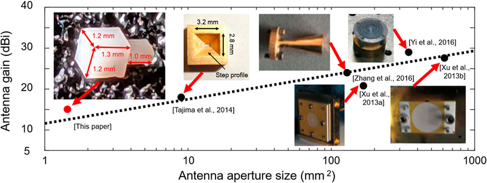
FIGURE 1. Antenna gain vs. antenna aperture size for recently developed antennas operating in the 300-GHz band.
Recently, we proposed a mesoscopic dielectric cuboid antenna (DCA) operating at 24 GHz and measured its fundamental characteristics (Samura et al., 2019). The proposed DCA is based on the terajet effect (Pacheco-Peña et al., 2014; Nguyen Pham et al., 2016), and exhibits a simple-structure with a size of 1.2λ × 1.2λ × 1.36λ. At 24 GHz, the DCA characteristics were experimentally demonstrated, exhibiting a 14.22 dBi gain and 21 and 34% narrower beamwidths in the E- and H-planes, respectively, compared with those of a horn antenna with the same dimensions. We also fabricated DCAs with a size of 1.36λ × 1.36λ × 1.79λ for operation in the 300 GHz band using machine milling and compared the near-field distribution of DCAs with that of an open-ended waveguide (Samura et al., 2020). Additionally, we examined the applicability of DCAs to a point-to-point THz wireless transmission using a high-gain diagonal horn receiving antenna (Yamada et al., 2021).
In this paper, a short-range 300 GHz wireless transmission is demonstrated using DCAs as transmitting and receiving antennas. DCAs with an aperture size of approximately 1.2 mm × 1.2 mm (1.2λ × 1.2λ at 300 GHz), which is comparable to that of a front camera lens installed in modern mobile phones, are fabricated. The antenna length is approximately 1.3 mm. The measured antenna gain of 15.06 ± 0.06 dBi is based on the two-antenna method (Mistry et al., 2019). Although this gain is 3 dB lower than that of a step-profiled corrugated horn antenna (Tajima et al., 2014), the aperture size and volume of the proposed antenna are reduced to approximately 1/6 (as shown in Figure 1) and 1/13, respectively. The measured bit-error-rate (BER) is less than 3.8 × 10⁻³ (forward error correction limit) (Chang et al., 2010) for a data rate of 17.5 Gbps at a transmission distance of 200 mm when two DCAs were used in the transmitter (Tx) and receiver (Rx) sides and at a transmission distance of 600 mm when DCA and a diagonal horn antenna were used in the Tx and Rx sides, respectively. These results demonstrate that the proposed DCA is a promising solution in intra-device communications and Kiosk download applications for future mobile devices operating in the 300 GHz band.
Characteristics of the J-Band DCA
The DCA, which was fabricated using machine milling, is shown in Figure 2A. The shape of a typical DCA is a cuboid with an antenna aperture size of approximately 1.2 mm × 1.2 mm and a length of approximately 1.3 mm. The material used for fabricating the DCA was polytetrafluoroethylene (PTFE) with a dielectric constant and loss tangent of 2.0 and 11 × 10–4 at 300 GHz, respectively (Stöckel 1993). The DCA features a protruded section of 0.8 mm × 0.4 mm × 1.0 mm to allow connection with a WR-3.4 rectangular waveguide, as shown in Figure 2B.
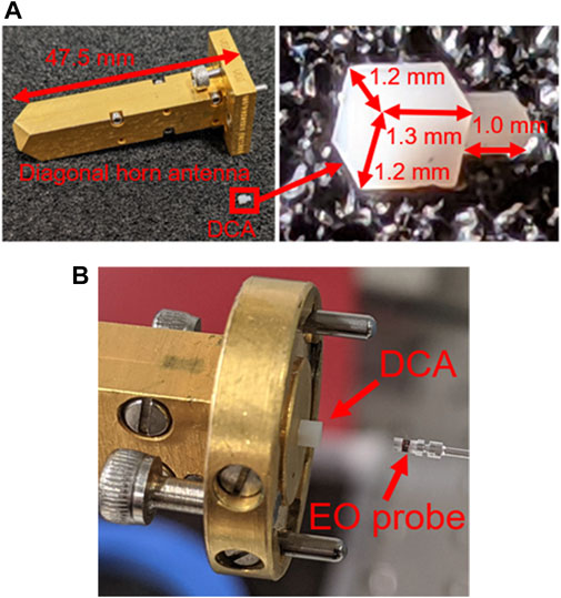
FIGURE 2. Photographs of the proposed DCA (A) Comparison with a diagonal horn antenna. The antenna aperture size is 1.2 mm × 1.2 mm, and the antenna length is approximately 1.3 mm. The DCA features a protruded section to allow connection with a WR-3.4 waveguide (B) Photograph of DCA connected to a WR-3.4 waveguide.
First, the amplitude and phase distribution of the near-field based on the electro-optic (EO) sensing technique (Hisatake et al., 2014) was measured to characterize the DCA radiation pattern. The measured field distribution at 300 GHz is shown in Figure 3A. The waveguide and DCA in this figure are depicted by the polygon data, i.e., the 3D simulation model, and the experimental and simulation results are compared to show the field distribution. In this measurement, a 16.7 GHz continuous wave signal was multiplied by 18 to generate a 300 GHz THz wave. The THz wave output power was approximately −3 dBm. Its amplitude and phase at a specific position were measured using an EO probe. This probe is composed of an organic EO crystal (DAST crystal) with dimensions 0.5 mm × 0.5 mm × 0.5 mm and a polarization-maintaining fiber. By conducting a special calibration experiment, it was confirmed that the disturbance by the EO probe can be neglected. The two-dimensional (2D) amplitude and phase distribution (X−Y plane) at 3.8 mm away from the antenna surface were visualized by moving the EO probe. Moreover, these distributions were visualized on the X−Z and Y−Z planes to demonstrate the radiation of the THz field by DCA. The measurement area was 20 mm × 20 mm for each plane. The EO probe kept moving at a 0.1 mm pitch, which is 1/10 of the operating wavelength. According to previous experimental studies (Hisatake et al., 2014), a spatial step of λ/10 is sufficient for high-fidelity visualization and far-field characterization. Thus, each plane contained 40,000 data points. The simulated amplitude and phase distribution results are shown in Figure 3B. The 2D distributions of amplitude and phase in the X−Z plane are also shown in Figure 3B. The simulation was performed using the CST Microwave Studio software, which employs the finite integration method. The mesh size was approximately 6 × 10⁸. The overall DCA measured characteristics, including amplitude distribution and phase front curvature, were found to agree well with the simulation results.
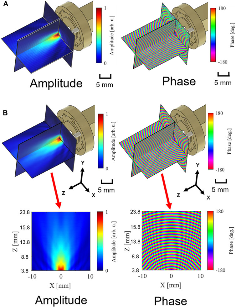
FIGURE 3. Amplitude and phase distribution of the THz wave radiated from DCA. The waveguide and DCA are depicted by the polygon data (A) Experimental results (B) Simulation results.
The 2D far-field distributions, which were calculated using the near-field distribution obtained from the measurement and simulation data, are shown in Figure 4A. The near-field to far-field transformation was based on the Fourier transformation of the near-field distribution (Balanis 1996). The far-field distributions were normalized to their maximum values. Also, the waveguide and DCA in this figure are depicted by the polygon data. The results obtained by extracting the one-dimensional data for the E- and H-planes are shown in Figure 4B. Here, the simulation results were normalized to their maximum value, and the experimental results were fitted to the simulation results. Small ripples in the E-plane can be observed both in the simulation and experimental results. The experimentally obtained radiation patterns roughly agree with those obtained from the simulation results, except for the ripple position. The various parameters of the radiation pattern characteristics are summarized in Table 1. The full width at half maximum (FWHM) of the far-field pattern calculated using the measured near-field pattern is 23.0° in both the E- and H-planes. The FWHM of the far-field pattern calculated using the simulated near-field pattern is 32.2° in the E-plane and 31.4° in the H-plane, respectively. Relatively large discrepancies between the simulation and experimental results can be observed. These discrepancies are mainly due to the ripple position. Note that it has been confirmed that the longer the DCA length, the smoother the far-field pattern (Yamada et al., 2021) is. On the other hand, the sidelobe positions and the main-to-sidelobe ratio agree well with the simulation results. In the transmission experiment conducted, the antenna gain is the most important parameter. However, accurate sidelobe characterization is also important in a realistic situation to evaluate the interference among different systems.
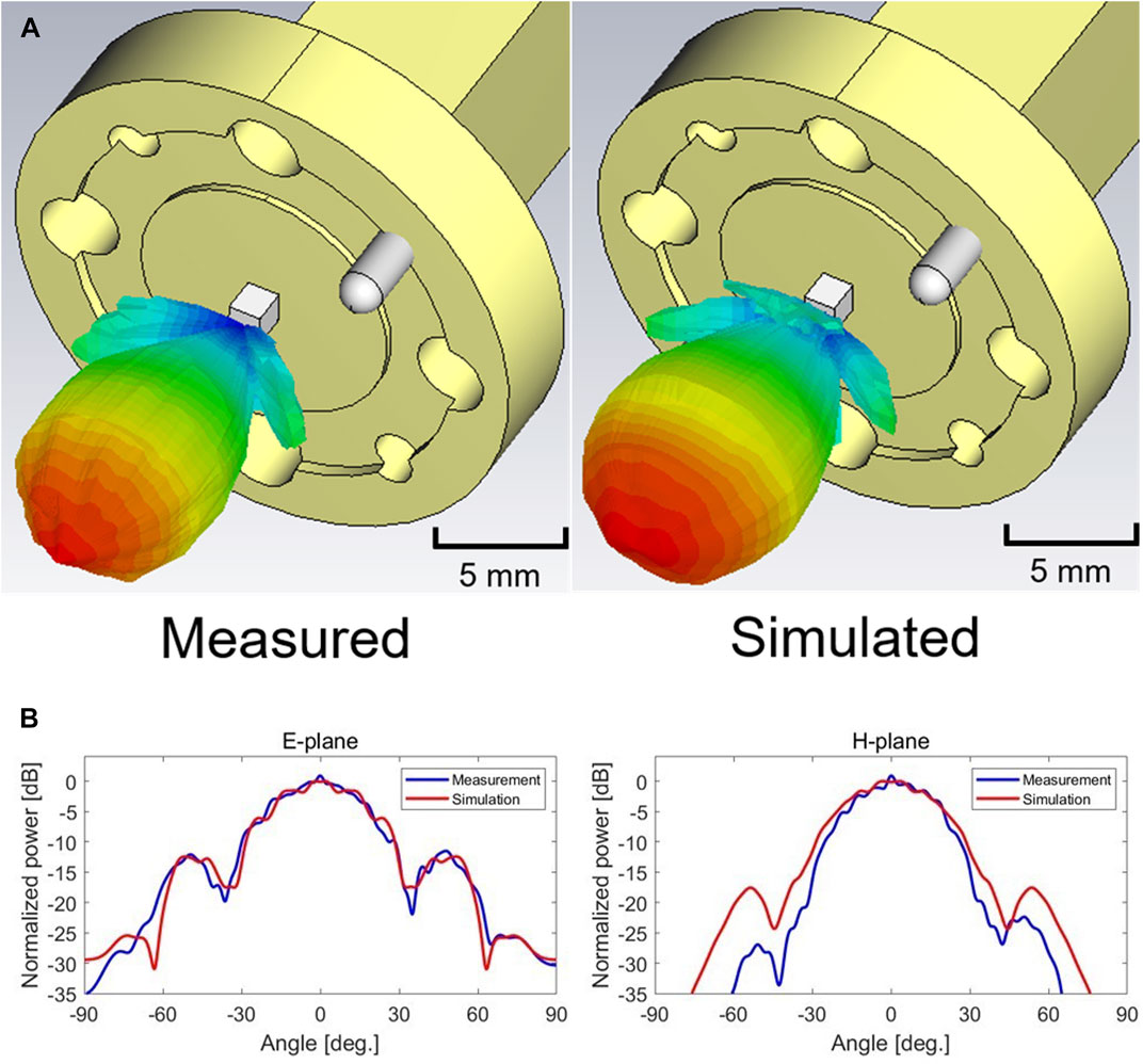
FIGURE 4. DCA radiation pattern (A) 2D radiation pattern calculated from the measured and simulated near-field distribution (B) One-dimensional radiation pattern in the E- and H-planes extracted from the 2D data.
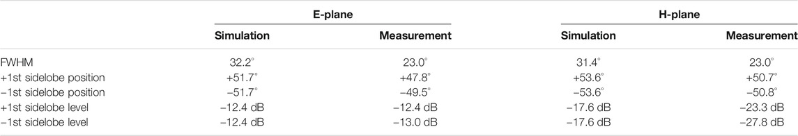
TABLE 1. Comparison of the simulated and measured radiation pattern characteristics.
Next, the antenna gain was measured, according to the two-antenna method in the far-field condition. A conical horn antenna was used as the reference antenna. The separation between the two antennas was 70 mm, which satisfies the far-field condition for a separation longer than 2D/λ = 63 mm, where D = 5.6 mm is the diameter of the conical horn antenna. The input and output power of the antennas was measured using a power meter (Erickson PM5). To account for the standing-wave effect, the received power was measured by varying the distance between the antennas from 70 to 71 mm with a 0.1-λ-step. The measured values were averaged for the gain calculation. The calculated gain of the conical horn antenna was Gc = 22.39 ± 0.01 dBi, assuming that the gains of the two conical antennas are exactly equal. The standard measurement error was estimated as 0.01 dB by evaluating the standard error of the power and distance measurements with a 95% confidence level in the Student’s t-distribution. Then, the DCA antenna gain was determined as 15.06 ± 0.06 dBi using the same procedure and the conical horn antenna as the reference antenna. The calculated frequency characteristic of the gain of DCA at the 220–330 GHz band is shown in Figure 5. The calculation was performed using CST Microwave Studio software. The highest gain was achieved at ∼300 GHz, and the −3dB bandwidth covered the entire bandwidth of the WR-3.4 waveguide (220–330 GHz).

FIGURE 5. Calculated frequency characteristic of the antenna gain of DCA. The calculation was performed using CST Microwave Studio software, and the gain results were used.
300 GHz Band Transmission Experiment Using DCAs
The experimental setup used for the THz wireless transmission at 300 GHz is shown in Figure 6. This setup is based on the photonics technology for the Tx and the electrical technology for the Rx. On the Tx side, the optical frequency comb was generated using an electro-optic modulator (EOM) driven by a 25 GHz electrical signal. By removing the unwanted components of the optical frequency comb using an optical filter, an optical two-tone signal with a separation of 300 GHz was generated. This signal was modulated by a Mach–Zehnder modulator (MZM) using an on-off keying (OOK) signal generated by a pulse-pattern generator (PPG). The test patterns were pseudo-random bit sequences with a length of 215–1. The line rate was 17.5 Gbps. The modulated optical two-tone signal was photo-electrically converted to a 300 GHz signal using a uni-traveling-carrier photodiode (UTC-PD) to convert the optical OOK signal to a THz amplitude-shift keying signal. The UTC-PD output power (approximately −15 dBm) was amplified to approximately 1 dBm using a medium-power amplifier (MPA). In the Rx side, a local-oscillator (LO) signal was generated by electrically multiplying the 25 GHz signal by a factor of 12. In this proof-of-concept experiment, the same 25 GHz signal was used in the Rx and Tx to reduce the relative frequency instability between the RF and LO signals to accurately evaluate the applicability of DCAs to the THz wireless transmission. The baseband signal extracted from the receiver was amplified by a pre-amplifier and reshaped using a limiting amplifier. The BER and eye-pattern characteristics were measured using a bit-error-rate tester (BERT) scope (Tektronix: BSA175C). The received signal spectrum was also measured using an electrical spectrum analyzer.
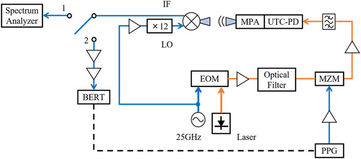
FIGURE 6. Experimental setup for the transmission experiment. EOM: electro-optic modulator, MZM, Mach–Zehnder modulator; UTC-PD, unitraveling -carrier photodiode; MPA, medium-power amplifier; BERT, bit-error-rate tester; PPG, pulse-pattern generator.
Three transmission experiments were conducted using different combinations of Tx and Rx antennas, as shown in Figure 7. The antennas used in each experiment are summarized in Table 2. In experiment I, a rectangular horn antenna with a gain of 24.87 ± 0.01 dBi and a diagonal horn antenna with a gain of 22.71 ± 0.03 dBi were used for the Tx and Rx, respectively. The total antenna gain of the link was 24.87 + 22.71 = 47.58 dBi. In experiment II, a DCA with a gain of 15.06 ± 0.06 dBi and a diagonal horn antenna with a gain of 22.71 ± 0.03 dBi were used for the Tx and Rx, respectively. The total antenna gain of the link was 15.06 + 22.71 = 37.77 dBi. In experiment III, a DCA was used for the Tx, and a DCA was used for the Rx. Absorbers with a reflection loss of approximately −15 dB at 300 GHz (Fujita et al., 2020) were attached to the waveguide’s metallic facet to reduce the standing-wave effect since standing waves affect the transmission quality at short transmission distances. The gains of the DCAs with the absorbers were measured, and it was found that these gains were slightly reduced by approximately 0.5 dB, as shown in Table 2. This is due to the absorption of the evanescent waves generated by the absorber around the DCAs. As a result, the total antenna gain of the link in experiment III was 14.72 + 14.53 = 29.25 dBi. The additional link losses relative to the link loss in experiment I were calculated from the total antenna gain in each link. These losses are also shown in Table 2.
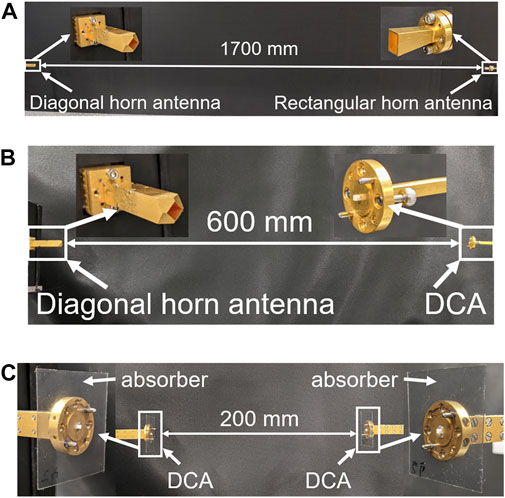
FIGURE 7. Photographs of three transmission experiments. (A) Experiment I. Tx, Rectangular horn antenna; Rx, Diagonal horn antenna. (B) Experiment II. Tx, DCA; Rx, Diagonal horn antenna. (C) Experiment III. Tx, DCA; Rx, DCA.
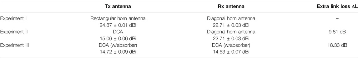
TABLE 2. Antennas and additional link losses in the three transmission experiments.
Before the BER measurement, the received signal spectra were obtained from the experiments I, II, and III, as shown in Figure 8. These spectra were obtained under the same BER conditions. Although all baseband signal spectra above 15 GHz are different from the original signal (which was measured by directly connecting the PPG to the spectrum analyzer) no bandwidth reduction or spectral distortion up to 26.5 GHz was observed, regardless of the different antenna combinations.
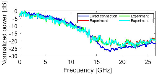
FIGURE 8. Received signal spectra. The data rate was 17.5 Gbps. The spectra were obtained under the same BER conditions.
The BER characteristics as a function of the transmission distance are shown in Figure 9. The black triangles, black squares, and black circles depict the data obtained using the Tx and Rx antennas in the form of a rectangular horn antenna and a diagonal horn antenna (experiment I), a DCA and a diagonal horn antenna (experiment II), and two DCAs (experiment III), respectively. In experiment I, a BER of 3.60 × 10⁻⁹ was achieved at a transmission distance of approximately 200 mm. The longer the transmission distance, the greater the propagation loss and the worse the BER are. A forward error correction limit (FEC limit) of 3.8 × 10⁻³ was achieved at a transmission distance of approximately 1700 mm. By changing the rectangular horn to DCA at the Tx side, a BER of 3.27 × 10⁻⁸ was achieved at a transmission distance of approximately 40 mm, and the FEC limit was achieved at approximately 600 mm (experiment II). In experiment III, using a DCA in the Tx and a DCA in the Rx, a BER of 7.51 × 10⁻⁷ was achieved at approximately 50 mm, and the FEC limit was achieved at approximately 200 mm. A transmission distance of ∼200 mm is required for the Kiosk download applications (Thomas, 2020). In the Kiosk download applications, a high-gain antenna with a power amplifier can be installed on the Kiosk terminal, which is similar to experiment II. An antenna with the gains of 22 and 28 dBi would extend the transmission distance to 500 and 1,000 mm, respectively, which are sufficient for the Kiosk download applications. The overall BER values in experiments II and III decrease compared with those of experiment I, due to the extra path loss originating from the antenna gain difference between the horn antennas and DCAs. This effect can be confirmed by calculating the transmission distance required to compensate for the extra path loss (
where R1 is the distance between the Tx and Rx in experiment I. The red squares and red circles depict the calculated characteristics obtained from the experiment I data. The calculations were based on the above equation, considering the extra pass losses
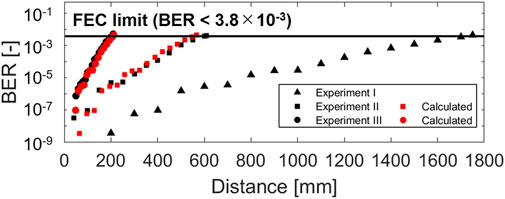
FIGURE 9. BER characteristics in each transmission experiment. The red squares and red circles depict the calculated characteristics obtained from the experiment I data. The calculations were based on Friis’s formula, considering the extra link losses shown in Table 2.
Conclusion
A short-range THz wireless transmission in the 300 GHz band was demonstrated using mesoscopic wavelength-scaled DCAs as transmitting and receiving antennas at a line rate of 17.5 Gbps. The DCA gain, which was measured according to the two-antenna method, was approximately 15 dBi. The BER characteristics as a function of the transmission distance were measured by conducting three experiments using the following: 1) a horn antenna for the Tx and a horn antenna for the Rx, 2) a DCA for the Tx and a horn antenna for the Rx, and 3) a DCA for the Tx and a DCA for the Rx. It was confirmed that the degradation of the BER characteristics in the experiment using two DCAs compared with those obtained in the experiment using two horn antennas can be quantitatively explained by the antenna gain difference between the horn antennas and the DCAs. Using off-the-shelf Tx/Rx modules, we achieved a BER of less than 3.8 × 10⁻³ over the transmission distance of 200 mm with two DCAs and 600 mm with DCA and a diagonal horn antenna. These results indicate that the DCA is a promising antenna type in intra-device communications and Kiosk download applications for future mobile devices operating at 300 GHz.
Data Availability Statement
The original contributions presented in the study are included in the article, further inquiries can be directed to the corresponding author.
Author Contributions
KY, YS, and SH contributed to conception and design of the study. KY and YS performed the experiments and data analysis. SH supported the experiments and data analysis. AK, NS, and JN supplied the experimental equipment. KY and SH wrote the manuscript. OM, AK, NS, JN, and IM wrote sections of the manuscript. All authors contributed to manuscript revision, read, and approved the submitted version.
Funding
This research is partially supported by funding from Horizon 2020, the European Union’s Framework Program for Research and Innovation under grant agreement No. 814523. ThoR has also received funding from the National Institute of Information and Communications Technology in Japan. The work by IM and OM was conducted within the framework of the Tomsk Polytechnic University Competitiveness Enhancement Program. We are grateful to Maxell, Ltd. for providing us EM-wave absorption sheet in 300 GHz band.
Conflict of Interest
Author JN is employed by the company SoftBank.
The remaining authors declare that the research was conducted in the absence of any commercial or financial relationships that could be construed as a potential conflict of interest.
References
Applications Requirement Document (ARD) (2015). DCN: 15-14-0304-16-003d. IEEE 802.15 TG3d. Available at: https://mentor.ieee.org/802.15/documents Accessed April 2, 2021.
Chang, F., Onohara, K., and Mizuochi, T. (2010). Forward Error Correction for 100 G Transport Networks. IEEE Commun. Mag. 48, S48–S55. doi:10.1109/mcom.2010.5434378
Dan, I., Ducournau, G., Hisatake, S., Szriftgiser, P., Braun, R.-P., and Kallfass, I. (2020). A Terahertz Wireless Communication Link Using a Superheterodyne Approach. IEEE Trans. THz Sci. Technol. 10, 32–43. doi:10.1109/tthz.2019.2953647
Dan, I., Schoch, B., Eren, G., Wagner, S., Leuther, A., and Kallfass, I. (2017). “A 300 GHz MMIC-Based Quadrature Receiver for Wireless Terahertz Communications,” in 42nd International Conference on Infrared, Millimeter, and Terahertz Waves (IRMMW-THz), 27 August-1 September 2017, Cancun, Mexico 1–2. doi:10.1109/irmmw-thz.2017.8066891
Fujita, M., Toyoda, M., Hara, S., Watanabe, I., and Kasamatsu, A. (2020). “Design of Electromagnetic Wave Absorption Sheet with Transparency and Flexibility in Sub-THz Bands,” in 2020 IEEE International Symposium on Radio-Frequency Integration Technology (RFIT), 2-4 September 2020, Hiroshima, Japan, 82–84. doi:10.1109/RFIT49453.2020.9226177
Grötsch, C., Tessmann, A., Leuther, A., and Kallfass, I. (2017). “Ultra-wideband Quadrature Receiver-MMIC for 240 GHz High Data Rate Communication,” in 42nd International Conference on Infrared, Millimeter, and Terahertz Waves (IRMMW-THz), 27 August-1 September 2017, Cancun, Mexico, 1–2. doi:10.1109/irmmw-thz.2017.8066868
Harter, T., Adib, M. M. H., Wolf, S., Muehlbrandt, S., Weber, M., Blaicher, M., et al. (2017). “Wireless Multi-Subcarrier THz Communications Using Mixing in a Photoconductor for Coherent Reception,” in 2017 IEEE Photonics Conference (IPC), October 1-5, 2017, Orlando, FL, 147–148. doi:10.1109/ipcon.2017.8116044
Hisatake, S., Pham, H. H. N., and Nagatsuma, T. (2014). Visualization of the Spatial-Temporal Evolution of Continuous Electromagnetic Waves in the Terahertz Range Based on Photonics Technology. Optica 1, 365–371. doi:10.1364/OPTICA.1.000365
Hamada, H., Fujimura, T., Abdo, I., Okada, K., Song, H., Sugiyama, H., et al. (2018). 300-GHz. 100-Gb/s InP-HEMT Wireless Transceiver Using a 300-GHz Fundamental Mixer 2018 IEEE/MTT-S International Microwave Symposium (IMS), June 10-15, 2018, Philadelphia, PA, 1480–1483. doi:10.1109/MWSYM.2018.8439850
Kallfass, I., Dan, I., Rey, S., Harati, P., Antes, J., Tessmann, A., et al. (2015). Towards MMIC-Based 300GHz Indoor Wireless Communication Systems. IEICE Trans. Electron. E98.C, 1081–1090. doi:10.1587/transele.E98.C.1081
Mistry, K. K., Lazaridis, P. I., Zaharis, Z. D., Akinsolu, M. O., Liu, B., and Loh, T. (2019). “Accurate Antenna Gain Estimation Using the Two-Antenna Method,” in Antennas and Propagation Conference 2019 (APC-2019), November 11-12, 2019, Birmingham, UK. doi:10.1049/cp.2019.0717
Pacheco-Peña, V., Beruete, M., Minin, I. V., and Minin, O. V. (2014). Terajets Produced by 3D Dielectric Cuboids. Appl. Phys. Lett. 105 (No. 8), 084102. doi:10.1063/1.4894243
Nguyen Pham, H. H., Hisatake, S., Minin, I. V., Minin, O. V., and Nagatsuma, T. (2016). Three-dimensional Direct Observation of Gouy Phase Shift in a Terajet Produced by a Dielectric Cuboid. Appl. Phys. Lett. 108 (19), 191102. doi:10.1063/1.4949014
Samura, Y., Horio, K., Antipov, V. B., Shipilov, S. E., Eremeev, A. I., Minin, O. V., et al. (2019). Characterization of Mesoscopic Dielectric Cuboid Antenna at Millimeter-Wave Band. Antennas Wirel. Propag. Lett. 18, 1828–1832. doi:10.1109/lawp.2019.2930820
Samura, Y., Yamada, K., Minin, O. V., Kanno, A., Sekine, N., Nakajima, J., et al. (2020). “High-gain and Low-Profile Dielectric Cuboid Antenna at J-Band,” in 2020 14th European Conference on Antennas and Propagation (EuCAP), March 15-20, 2020, Copenhagen, Denmark, 1–4. doi:10.23919/EuCAP48036.2020.9135438
Schoch, B., Tessmann, A., Leuther, A., Wagner, S., and Kallfass, I. (2019). “300 GHz Broadband Power Amplifier with 508 GHz Gain-Bandwidth Product and 8 dBm Output Power,” in 2019 IEEE MTT-S International Microwave Symposium (IMS), June 2-7, 2019, Boston, MA, 1249–1252. doi:10.1109/mwsym.2019.8700754
Son, H., Kim, D., Song, K., Cho, J., and Rieh, J. (2018). “A 300-GHz Integrated Transmitter Based on InP HBT Technology,” in 2018 Asia-Pacific Microwave Conference (APMC), November 6-9, 2018, Kyoto, Japan, 524–526. doi:10.23919/apmc.2018.8617621
Stöckel, B. (1993). QUASI-OPTICAL MEASUREMENT OF COMPLEX DIELECTRIC CONSTANT AT 300 GHz. Int. J. Infrared Millimeter Waves 14 (No. 10), 2131–2148. doi:10.1007/bf02096378
Tajima, T., Song, H.-J., Ajito, K., Yaita, M., and Kukutsu, N. (2014). 300-GHz Step-Profiled Corrugated Horn Antennas Integrated in LTCC. IEEE Trans. Antennas Propagat. 62, 5437–5444. doi:10.1109/tap.2014.2350520
Thomas, K. (2020). “THz Communications – A Candidate for a 6G Radio?,” in The 22nd International Symposium on Wireless Personal Multimedia Communications (WPMC – 2019) November 24-27, 2019, Lisbon, Portugal. doi:10.24355/dbbs.084-202008031406-0
Xu, J., Chen, Z. N., and Qing, X. (2013a). 270-GHz LTCC-Integrated High Gain Cavity-Backed Fresnel Zone Plate Lens Antenna. IEEE Trans. Antennas Propagat. 61, 1679–1687. doi:10.1109/tap.2012.2232261
Xu, J., Chen, Z. N., and Qing, X. (2013b). 270-GHz LTCC-Integrated Strip-Loaded Linearly Polarized Radial Line Slot Array Antenna. IEEE Trans. Antennas Propagat. 61, 1794–1801. doi:10.1109/tap.2012.2237007
Yamada, K., Samura, Y., Minin, O. V., Kanno, A., Sekine, N., Nakajima, J., et al. (2021). “Short-range Wireless Transmitter Using Mesoscopic Dielectric Cuboid Antenna in 300-GHz Band,” in 2020 50th European Microwave Conference (EuMC), January 12-14, 2021, Utrecht, Netherlands, 195–198. doi:10.23919/EuMC48046.2021.9338193
Yi, H., Qu, S.-W., Ng, K.-B., Chan, C. H., and Bai, X. (2016). 3-D Printed Millimeter-Wave and Terahertz Lenses with Fixed and Frequency Scanned Beam. IEEE Trans. Antennas Propagat. 64, 442–449. doi:10.1109/tap.2015.2505703
Keywords: mesoscopic dielectric cuboid antenna, low-profile antenna, terahertz wireless communication, electro-optic sensing, antenna gain measurement, 300 GHz band transmission experiment
Citation: Yamada K, Samura Y, Minin OV, Kanno A, Sekine N, Nakajima J, Minin IV and Hisatake S (2021) Short-Range Wireless Transmission in the 300 GHz Band Using Low-Profile Wavelength-Scaled Dielectric Cuboid Antennas. Front. Comms. Net 2:702968. doi: 10.3389/frcmn.2021.702968
Received: 30 April 2021; Accepted: 02 July 2021;
Published: 16 July 2021.
Edited by:
Ke Wang, RMIT University, AustraliaReviewed by:
Mohamed Shehata, University of Adelaide, AustraliaFawad Sheikh, University of Duisburg-Essen, Germany
Copyright © 2021 Yamada, Samura, Minin, Kanno, Sekine, Nakajima, Minin and Hisatake. This is an open-access article distributed under the terms of the Creative Commons Attribution License (CC BY). The use, distribution or reproduction in other forums is permitted, provided the original author(s) and the copyright owner(s) are credited and that the original publication in this journal is cited, in accordance with accepted academic practice. No use, distribution or reproduction is permitted which does not comply with these terms.
*Correspondence: Shintaro Hisatake, aGlzYXRha2VAZ2lmdS11LmFjLmpw