 Jae-Yeong Lee
 Jaehyun Choi2
 Wonbin Hong
- 1Department of Electrical Engineering, Pohang University of Science and Technology, Pohang, South Korea
- 2AiP Department, Substrate and Material Business Unit, LG Innotek, Seoul, South Korea
This paper presents a design methodology focused on feeding networks that can improve the insertion loss and coverage efficiencies of millimeter-wave (mm-Wave) phased arrays in mobile terminals. This enhancement is accomplished by using a grounded coplanar waveguide (GCPW) transmission line (TL) with via fences fabricated on single-layer FR-4 PCB. The exemplified 8-element phased arrays incorporating a compact one-dimensional electromagnetic bandgap (1-D EBG) antenna are fed through a 1 × 8 T-junction power divider, which includes the predetermined phased delay lines. To achieve high radiation performance with minimum leakage power or spurious waves in the T-junction power divider, an island-shape GCPW TL topology with via fences featuring high-impedance surfaces (HIS) is devised and fabricated. For further investigation on the radiation performance and spherical coverage of the mm-Wave mobile antenna, a mobile device prototype equipped with two sets of the 8-element phased arrays is prepared and studied. Through extensive simulation and experimental studies, it can be ascertained that the proposed GCPW TL topology with via fences can improve the realized gain at a coverage efficiency of 50% by more than 3 dB, between 26 and 36 GHz.
Introduction
Millimeter-wave (mm-Wave) 5G mobile communication promises to address the increasingly severe bandwidth shortage issues being driven by the exponential growth in global wireless data traffic (Rappaport et al., 2013; Roh et al., 2014). For each global region, the required communication quality of service (QoS) has mainly been established using spectrum classifications below 30 GHz (N257, N258, N261) and above 30 GHz (N260) (3GPP, 2019). The effective isotropic radiated power (EIRP) and coverage efficiency [or cumulative distribution function (CDF)] are key performance benchmarks for mm-Wave 5G devices (Zhao et al., 2019; Huo et al., 2019). Recently, to realize seamless global roaming services, mm-Wave antennas for user equipment (UE) have been investigated, which can provide spherical coverage characteristics across multi-band and broadband spectrums (Hong et al., 2017; Syrytsin et al., 2018; Huo et al., 2019; Zhao et al., 2019). The cost-effective UE design methodologies for implementing mm-Wave antenna modules, consisting of radio frequency integrated circuits (RFIC), have recently attracted interest (Hong et al., 2017; Hong et al., 2012; Hong et al., 2013). Despite their poor fabrication resolution and relatively high lossy media, mm-Wave antenna fabricated on multi-layer FR-4 substrates or single-layer printed circuit board (PCB) has emerged as promising candidates for low-cost mobile terminals.
Various antenna elements and feeding networks have been investigated to realize wideband mm-Wave UE phased arrays with spherical coverage (Hong et al., 2012; Hong et al., 2013; Lee and Nam, 2017; Moghaddam et al., 2020). In (Lee and Nam, 2017) and (Moghaddam et al., 2020), tightly coupled arrays are devised that used small antenna elements, with inter-element spacing below 0.5λ0. However, those antennas have been problematic to implement in large-scaled phased arrays due to the relatively high mutual coupling between antenna elements. In (Lee et al., 2019; Lee et al., 2021a; Lee et al., 2021b), low-coupled phased arrays incorporating one-dimensional (1-D) electromagnetic bandgap (EBG) antennas with via wall structures featuring high-impedance surfaces (HIS) have been considered.
Naturally, low-loss feeding networks are critical to achieve maximum coverage efficiencies with high threshold gain in phased arrays. Numerous feeding networks have been studied, including various transmission line types and low-loss transition structures (Hong et al., 2012; Hong et al., 2013; Haydl, 2002; Zhou and Melde, 2008; Sain and Melde, 2016). However, the fundamental research, such as power flow analysis and optimized structures, has still not been sufficient to establish low-loss feeding networks in mobile terminal antenna and to realize spherical coverage at low production cost.
This paper presents a methodology to reduce the insertion loss of feeding networks in single-layer FR-4 PCB based mm-Wave phased arrays and to increase coverage efficiency in mobile terminals. Despite the poor fabrication resolution and large loss materials, an island-shape grounded coplanar waveguide (GCPW) transmission line (TL) with via fences featuring HIS can suppress parallel-plate waveguide modes and surface-waves. The fundamental power flow has been analyzed by comparing the performance of various feeding networks, and it can be ascertained that the GCPW TL with via fences exhibits low-loss on single-layer FR-4 PCBs. Afterwards, to investigate the optimal feeding networks in the mobile terminal, three types of feeding networks, consisting of a 1 × 8 T-junction power divider with a predetermined phased delay, are combined with 8-elements incorporating 1-D EBG antennas. In the handset configuration, two sets of the phased arrays including three types of feeding networks have been mounted on the top and bottom for massive multiple-input multiple-output (MIMO) configurations. Then, using simulation and experimental studies, the performance and coverage characteristics of the three types of the fabricated phased arrays are compared and discussed. Finally, the performance of the proposed phased arrays, including GCPW TL with via fences mounted on the edge of the mobile terminals, are compared with state-of-the-art mm-Wave phased arrays.
Design of Three Types of Feeding Networks
Design Consideration and Configuration of Three Types of Feeding Networks
As illustrated in Figure 1, three types of TLs with symmetric connector landing pads are fabricated on the FR-4 PCB to investigate the optimized feeding networks within identical characteristic impedance, and to analyze the fundamental power flow (Zhou and Melde, 2008). At 28 GHz, the relative permittivity and dielectric loss tangent of the FR-4 substrate are 4.4 and 0.032, respectively (Lee et al., 2021b). In order to achieve same characteristic impedance, the CPW TL, the GCPW TL without via fences, and the GCPW TL with via fences are designed with the same signal width (W2), the same gap (S) between signal and top-sided ground planes, and the same TL length (L). Moreover, for a proper performance comparison, the identical characteristic impedance of the TLs within an almost identical electrical length should be close to 50-Ω, on the condition that meets PCB design rule with compact size (Lee et al., 2021b). Thus, the characteristic impedances of the three types of feeding networks are almost identical, ranging from 65 to 69-Ω. In order to remove the concerns on the parasitic effects of connector landing pads and impedance mismatch condition, identical connector landing pads with via fence embedded CPWG TL featuring 50–65-Ω characteristic impedance have been utilized in all cases (Lee et al., 2021b). The via fences are inserted into the GCPW TL to function as HIS that can suppress the parallel-plate waveguide modes and surface-waves.
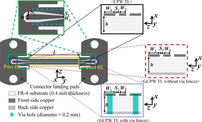
FIGURE 1. Back-to-Back Configurations of three types of feeding networks with symmetric connector landing pads (h = 0.4 mm, W1 = 0.4 mm, W2 = 0.2 mm, W3 = 0.6 mm, S1 = 0.1 mm, S2 = 0.2 mm, L = 10 or 20 mm).
Fundamental Power Flow Analysis of the Three Types of Feeding Networks
Figures 2, 3 illustrate the simulated and measured fundamental power flow analysis, using the three types of fabricated feeding networks samples along their respective lengths (L = 10 or 20 mm). According to fundamental transmission line theory, the total loss in TLs is equal to the sum of the dielectric loss, conduction loss and leakage power. The total loss ratio can be obtained using the measured results of the two-port S-parameters, according to 1) (Haydl, 2002; Zhou and Melde, 2008; Sain and Melde, 2016). The total loss ratio (TL) is defined as
where internal loss is the sum of the dielectric loss and the conduction loss. Dielectric loss and conduction loss typically occur due to the FR-4 substrate and metal conductors, respectively. However, extracting and analyzing the total loss remains elusive. Hence, the simulated leakage power ratio can be achieved according to (2), as reported in (Mehdipour and Eleftheriades, 2014; ANSYS Electronics HFSS, 2021).
where leakage power is defined as the power flow escaping in the outward direction of the TL in the form of parallel-plate waveguide modes and surface-waves.
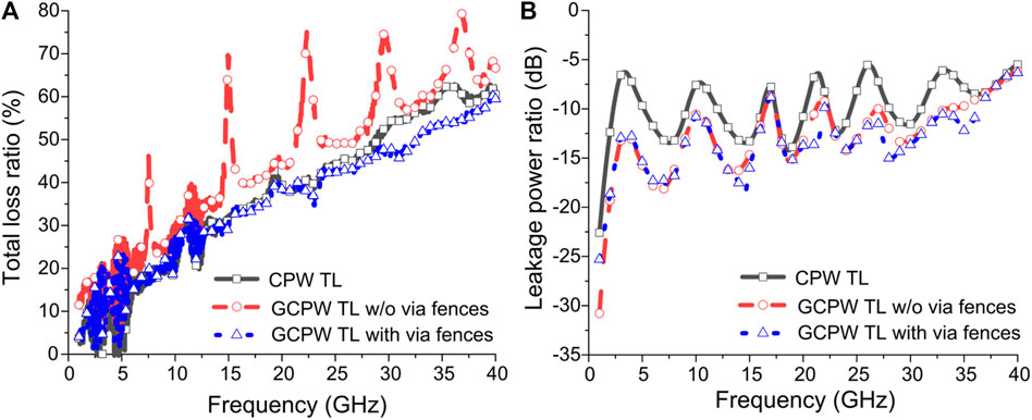
FIGURE 2. L = 10 mm. (A) Measured total loss ratio. (B) Simulated leakage power ratio.
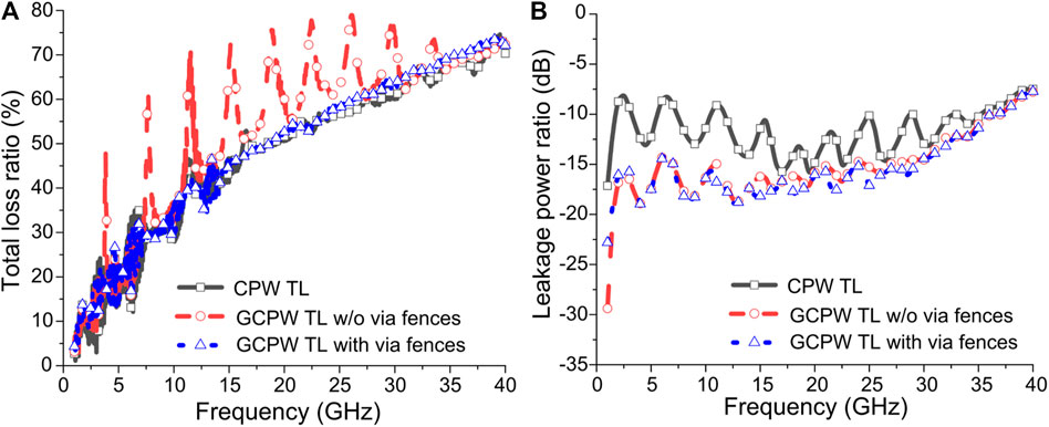
FIGURE 3. L = 20 mm. (A) Measured total loss ratio. (B) Simulated leakage power ratio.
As depicted inFigures 2A, 3A, the measured total loss ratio of the GCPW TL with via fences is reduced more than that of the other feeding networks. Since the total loss at the mm-Wave spectrum depends on the dielectric material properties of the FR-4 substrate, the dielectric loss cannot be easily suppressed. Meanwhile, the GCPW TL without via fences can cause parallel-plate waveguide mode, but the signal of the CPW TL can propagate through lateral field distribution between air and dielectric layers. This means that the dielectric loss of the CPW TL can be reduced more than that of the GCPW TL without via fences due to relatively low effective permittivity. However, the coupled slotline mode between two unconnected ground planes in the CPW TL can occur leading to increase of the leakage power loss, as illustrated in Figures 2B, 3B (Deal, 2008). Thus, due to suppression of parallel-plate waveguide mode by via fences featuring HIS, the total loss can efficiently be reduced in comparison to the GCPW TL without via fences. In addition, the leakage power loss of the GCPW TL with via fences featuring identical potential of two connected ground planes be also reduced more than that of the CPW TL by mitigation of the coupled slotline mode.
Millimeter-Wave Phased Array Antenna in Mobile Terminals
Millimeter-Wave Antenna Configuration and Experimental Setup for Mobile Terminals
To derive the optimized feeding network topology in mobile terminals, the electromagnetic characteristics and performance of the mm-Wave phased arrays containing various feeding networks are investigated and discussed. For realizing a reliable link budget and wide beam coverage in mm-Wave 5G UEs, the phased arrays have been designed consisting of 8-element linear arrays utilizing compact 1-D EBG antennas (Lee et al., 2021b). The inter-element spacing of the 1-D EBG antenna is 0.39λ0. In addition, T-junction power dividers including predetermined phase delays based on three types of feeding networks, are devised (Lee et al., 2021b). To achieve a 120° phased delay in T-junction power divider for ±60° beam steering at 28 GHz, the physical length difference of each adjacent antenna element in the predetermined phase delay part is 2 mm. For verification on wide angle scanning, three samples of phased arrays containing three types of feeding networks are fabricated at each beam steering direction (Sample A: boresight, Sample B: +maximum beam steering angle, Sample C: −maximum beam steering angle). Moreover, to realize the continuous scanning results and obtain the coverage efficiency, additional antennas are designed and utilized with predetermined phase delay lines, for ±15, ±30, and ±45° beam steering. For mm-Wave massive MIMO antenna systems featuring spherical coverage, two sets of 1 × 8 phased arrays are mounted onto the top and bottom polycarbonate carriers of the mobile mockup devices, as illustrated in Figure 4 (Wonbin Hong et al., 2014). The polycarbonate carriers exhibit a relative permittivity of 3.0 and a bulk conductivity of 0.075 S/m, respectively (Hong, 2017).
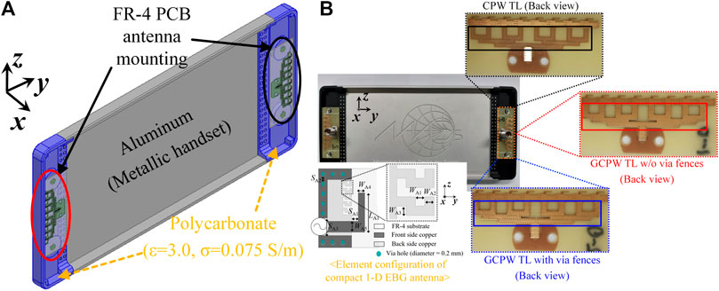
FIGURE 4. Phased arrays for mm-Wave mobile device. (A) 3-D Perspective view. (B) Photograph of the mm-Wave mobile device with various feeding networks (Antenna element: 1-D EBG antenna (2.1 mm × 3.6 mm), Detailed Dimensions: WA1 = 0.1 mm, WA2 = 0.1 mm, WA3 = 0.1 mm, WA4 = 0.3 mm, WA5 = 0.5 mm, LA1 = 1.8 mm, SA1 = 0.3 mm, SA2 = 0.25 mm, SA3 = 0.8 mm).
By using the PNA-X network analyzer N5247B, Figure 5 illustrates the experimental setup for measuring the far-field radiation performance in Radiation Performance of Phased Array Antennas in Mobile Terminals of the manuscript. A phased array mounted on the top carriers of the mobile mockup devices is activated, while the other phased array mounted on the bottom carriers of the mobile mockup devices is terminated with a 50-Ω load. To test the radiation performance of the proposed phased arrays in mobile terminals, the radiation patterns has been measured using standard gain horn antenna operating in the Ka-band.
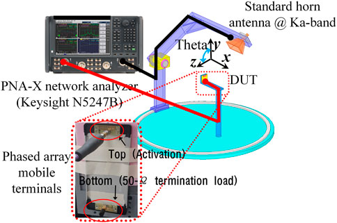
FIGURE 5. Experimental setup for radiation pattern measurement of the fabricated phased arrays in mobile terminals.
Radiation Performance of Phased Array Antennas in Mobile Terminals
To investigate the proximity coupling effects between adjacent polycarbonate carriers and the phased arrays in mobile terminals, the end-fire gain is measured and compared with three types of in-phase T-junction power divider. Despite the existence of larger thickness polycarbonate carriers (2.5 mm thickness) than the FR-4 substrate (0.4 mm thickness), Figures 6A,B illustrates that the antenna containing GCPW TL with via fences exhibits a robust high end-fire gain at co-polarization (Etheta). In particular, as depicted in Figure 6A, the array with the GCPW topology with via fences in the mobile terminals exhibits more than a 3 dB enhancement of end-fire, compared to the arrays of other feeding network topologies at Ka-band. Thus, because via fences featuring HIS can mitigate leakage power or spurious waves, the end-fire radiation characteristic can be nearly realized as in free space without any radiation distortion due to polycarbonate carriers.
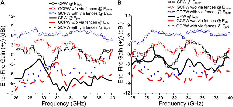
FIGURE 6. (A) Measured end-fire gain (+y) in free space. (B) Measured end-fire gain (+y) in handset mockup.
Figures 7–9 illustrate the measured radiation patterns of the phased arrays with three types of feeding networks in mobile terminals, using antenna samples with predetermined phase delays at 26, 30, and 36 GHz, respectively (Refer to Supplementary Figures 1−3 @ 28, 32, and 34 GHz). The radiation patterns of the antennas containing GCPW TL with via fences exhibit beam scanning coverage of more than 110° (±55°) within 3 dB scan loss. And the antennas containing GCPW TL with via fences are more highly directive than the antennas containing other feeding networks. In addition, since the via fences in GCPW TL can reduce the leakage power or spurious waves, the 3-dB beam width in the main beam becomes narrower, and the side lobe level is reduced. Thus, despite a little interaction with the polycarbonate carriers in the mobile terminals, high gain and wide-angle scanning capabilities within 10 GHz bandwidth and 3 dB scan loss are still preserved, due to the HIS properties of the via fences in GCPW TL.
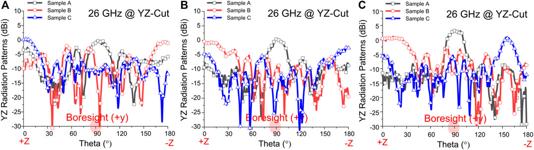
FIGURE 7. Measured radiation patterns (Etheta-polarization and 26 GHz) of the fabricated arrays for the beam steering test in the handset mockup. (A) CPW TL. (B) GCPW TL without via fences. (C) GCPW TL with via fences.
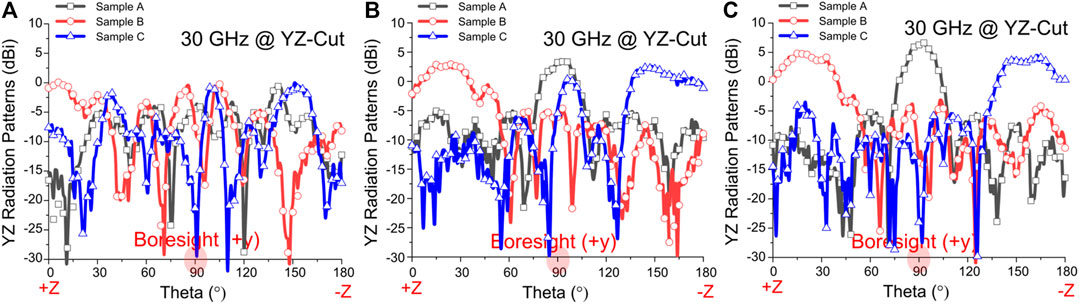
FIGURE 8. Measured radiation patterns (Etheta-polarization and 30 GHz) of the fabricated arrays for the beam steering test in the handset mockup. (A) CPW TL. (B) GCPW TL without via fences. (C) GCPW TL with via fences.
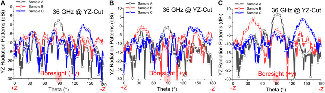
FIGURE 9. Measured radiation patterns (Etheta-polarization and 36 GHz) of the fabricated arrays for the beam steering test in the handset mockup. (A) CPW TL. (B) GCPW TL without via fences. (C) GCPW TL with via fences.
Spherical Coverage Analysis of Phased Array Antennas in Mobile Terminals
To realize quasi-isotropic spherical coverage using mm-wave antennas in mobile terminals, the maximum realized gain, which depends on the dielectric loss tangent of the antenna substrate and mutual coupling between antenna elements, should be high (Zhao et al., 2019; Syrytsin et al., 2018; Lee et al., 2021b; Li et al., 2020; Kim and Nam, 2020). Above all, for reliable spherical coverage, the difference between the realized gain at 0% coverage efficiency (or 100% CDF) and the realized gain at 50% coverage efficiency (or 50% CDF) should be reduced (Zhao et al., 2019; Kim and Nam, 2020). In this paper, the phased array antennas based on single-layer FR-4 PCB technology in mobile terminals, featuring extremely low production cost and small form factor, have been evaluated using the simulated total scan pattern (TSP) and coverage efficiency. To investigate the optimized feeding networks in mobile terminals, the simulated TSP and coverage efficiency are compared using three types of feeding networks.
Figures 10–12 illustrates the simulated TSP of the phased array antennas using CPW TL, GCPW TL without via fences, and GCPW TL with via fences at 26, 30, and 36 GHz, respectively (Refer to Supplementary Figures 4–6 @ 28, 32, and 34 GHz). By extracting maximum realized gain value at all angular distribution points, the TSP is attained in all continuous beam steering scenarios (Boresight, ±15, ±30, ±45, and ±60° beam steering angles) as shown in Figures 10–12 (Syrytsin et al., 2018; Lee et al., 2021b). The simulated coverage efficiency is also calculated, using the simulated TSP of the phased array antennas containing three types of feeding networks for frequency ranges from 26 to 36 GHz, as depicted in Figures 13, 14 (Zhao et al., 2019; Syrytsin et al., 2018; Lee et al., 2021b; Li et al., 2020). The lowest coverage is observed at 36 GHz, since larger beam squint can occur due to the large internal loss in the T-junction power divider at 36 GHz (Lee et al., 2021b). Due to the low-loss and low-leakage characteristics of the feeding networks, the phased array antennas containing GCPW TL with via fences featuring HIS can achieve quasi-isotropic spherical coverage within the high realized gain.
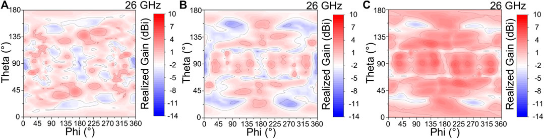
FIGURE 10. Simulated total scan patterns (26 GHz) of the designed array antennas in the handset mockup. (A) CPW TL. (B) GCPW TL without via fences. (C) GCPW TL with via fences.
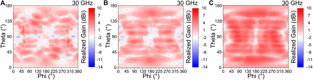
FIGURE 11. Simulated total scan patterns (30 GHz) of the designed array antennas in the handset mockup (A) CPW TL (B) GCPW TL without via fences (C) GCPW TL with via fences.
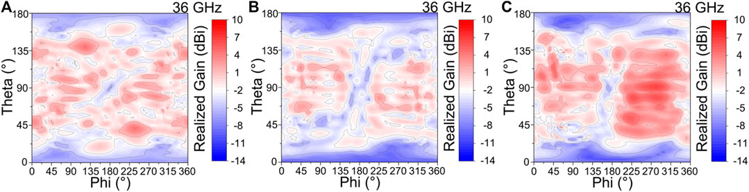
FIGURE 12. Simulated total scan patterns (36 GHz) of the designed array antennas in the handset mockup. (A) CPW TL. (B) GCPW TL without via fences. (C) GCPW TL with via fences.
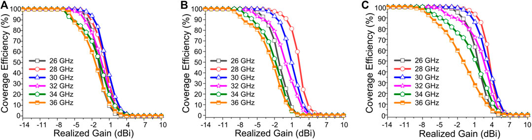
FIGURE 13. Simulated coverage efficiency (26–36 GHz) of the designed array antennas in the handset mockup. (A) CPW TL. (B) GCPW TL without via fences. (C) GCPW TL with via fences.
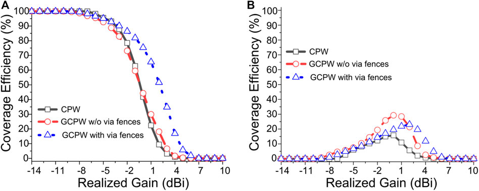
FIGURE 14. Statistical investigation (Frequency ranges from 26 to 36 GHz) of the simulated coverage efficiency of the designed array antennas in the handset mockup. (A) Average value. (B) Standard deviation value.
To further study coverage efficiency and the beam squint affect in the phased array antennas containing three types of feeding networks, a statistical investigation is conducted, as illustrated in Figure 14. Despite adjacent polycarbonate carriers, the 50% coverage efficiency of the antennas containing GCPW TL with via fences is improved by more 3 dB, from 26 to 36 GHz, in terms of the realized gain, compared with that of the antennas containing other feeding networks, as depicted in Figure 14A. The standard deviation of coverage efficiency of the antennas containing GCPW TL with via fences is more than 20% at the realized gain of 2.5 dBi, in Figure 14B. These standard deviation values can be understood considering the large insertion loss of the feeding networks, and the impact of beam squint at 36 GHz, due to the highly lossy FR-4 PCB dielectric substrate (Lee et al., 2021b; Lee et al., 2021c).
Performance Comparison
Table 1 lists a comparison of the performance of the designed phased array antennas containing three types of feeding networks. Due to HIS characteristics of the via fences, the GCPW TL with via fences can exhibit low insertion loss and low-leakage power during the back-to-back test. By suppressing both coupled slotline mode and parallel-plate waveguide mode by HIS characteristics of via fences in GCPW TL, the feeding networks containing the compressed power dividers can be reduced coupling or leakage power between adjacent feeding structures (Lee et al., 2021b). Eventually, the gain difference among the phased array antenna containing three types of feeding networks can be largely increased in the handset mockup test rather than in the back-to-back test. Moreover, in the handset mockup test, despite adjacent polycarbonate carriers, the antennas containing GCPW TL with via fences achieves robust radiation improvement compared with the antennas with other feeding networks, due to the unique electromagnetic property of the via fences. The antenna also provides high performance, including high end-fire gain, high radiation intensity between co-polarization and cross-polarization, and highly realized gain at 50% coverage efficiency.
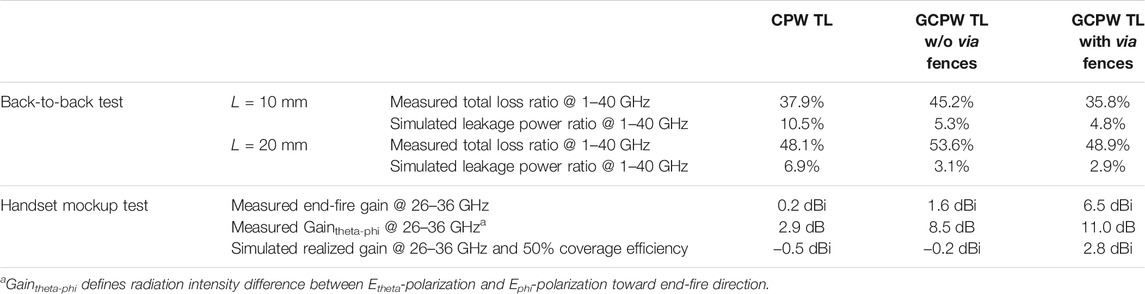
TABLE 1. Performance comparison (averaged value) of the phased array antennas containing three types of feeding networks.
Table 2 provides a comparison of these results and the state-of-the-art mm-Wave phased arrays mounted on the edge of mobile terminals. By using GCPW TL with via fences featuring HIS to reduce leakage power or spurious waves, the compact 1-D EBG array antennas based on a single-layer FR-4 PCB achieve wide-angle scanning capability in broadband for mm-Wave UE applications. Notably, the proposed antenna in this work exhibits quasi-isotropic spherical coverage with good radiation performance, while maintaining an extremely low production cost compared to state-of-the-art antennas presented (Hong et al., 2017; Syrytsin et al., 2018; Li et al., 2020; Kim and Nam, 2020).
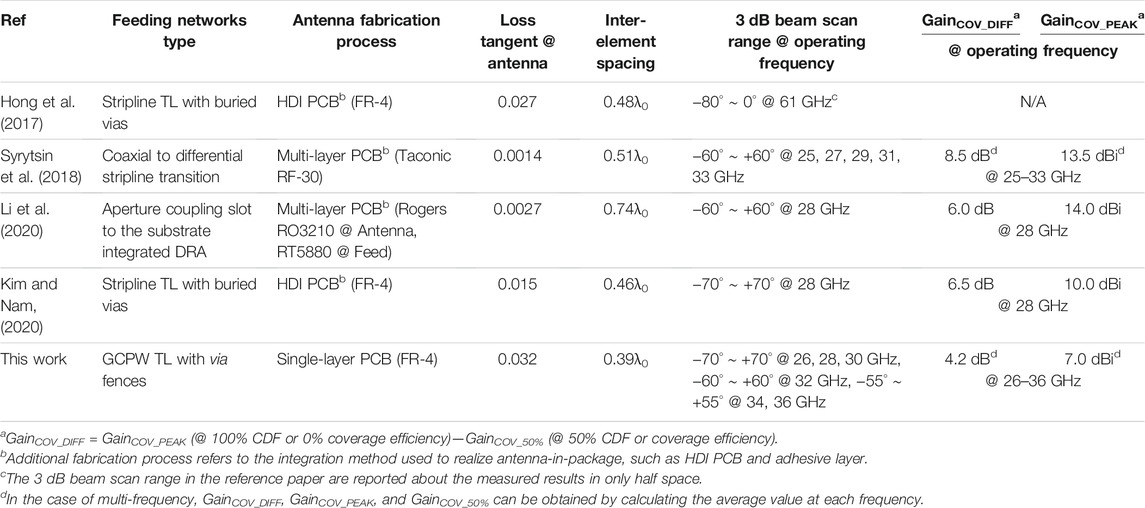
TABLE 2. Comparison of the state-of-the-art mm-wave phased arrays mounted on edge of mobile terminals.
Conclusion
This study proposes and characterizes a mm-Wave phased array containing GCPW TL with via fences based on single-layer FR-4 PCB for mobile UE applications. Using fundamental power flow analyses in back-to-back tests, and comparing the performance of various feeding networks, it is confirmed that the HIS unique property of the via fences in GCPW TL can improve the insertion loss of the feeding networks. Moreover, it can be ascertained that this feeding network can enable mm-Wave phased arrays with quasi-isotropic spherical coverage in mobile terminals. Due to its extremely low-cost fabrication, the presented phased array is a promising candidate for mm-Wave 5G global service in mobile devices.
By employing the preserved radiation performance of the GCPW TL topology with via fences against adjacent dielectric materials, this design and analysis methodology about fundamental power flow of feeding networks can be applied in sub-THz antenna-in-package (AiP) and antenna-on-chip (AoC) applications (Pan et al., 2014; Hagelauer et al., 2018).
Data Availability Statement
The original contributions presented in the study are included in the article/Supplementary Material, further inquiries can be directed to the corresponding authors.
Author Contributions
J-YL and WH conceived the idea of the feeding networks for mm-Wave phased arrays in mobile terminals. J-YL and JC conducted the fundamental power flow analysis of the feeding networks. J-YL, JC, BK, and YO conducted the simulations or performed the measurements of the handset mockup. J-YL and WH wrote the manuscript. All authors discussed the results and commented on the manuscript.
Funding
This research was supported by Basic Science Research Program through the National Research Foundation of Korea (NRF) funded by the Ministry of Education (Grant Nos. 2018R1A6A3A01013261 and 2021R1I1A1A01057159), in part by Next Generation Engineering Research Program of National Research Foundation of Korea (NRF) funded by the Ministry of Science, ICT (Grant No. 2019H1D8A2106519), and in part by Institute for Information and Communications Technology Planning and Evaluation (IITP) grant funded by the Korea government (MSIT) (Grant Nos. 2018-0-00733, 2018-0-00823, 2020-0-00858, and 2021-0-00763).
Conflict of Interest
Author JC is employed by LG Innotek.
The remaining authors declare that the research was conducted in the absence of any commercial or financial relationships that could be construed as a potential conflict of interest.
Publisher’s Note
All claims expressed in this article are solely those of the authors and do not necessarily represent those of their affiliated organizations, or those of the publisher, the editors and the reviewers. Any product that may be evaluated in this article, or claim that may be made by its manufacturer, is not guaranteed or endorsed by the publisher.
Acknowledgments
The authors would like to thank ANSYS Corporation and HANSAEM DIGITEC Corporation for their respective support of ANSYS simulation and PCB sample fabrication.
Supplementary Material
The Supplementary Material for this article can be found online at: https://www.frontiersin.org/articles/10.3389/frcmn.2021.741533/full#supplementary-material
References
3GPP (2019). Technical Specification Group Radio Access Network, Document TR 38.817-01 V 16.1.0. Available at: https://portal.3gpp.org/desktopmodules/Specifications/SpecificationDetails.aspx?specificationId=3359. (Accessed September 09, 2019).
ANSYS Electronics HFSS (2021). 3D High Frequency Simulation Software. Canonsburg, Pennsylvania, USA: ANSYS Corporation.
Deal, W. (2008). Coplanar Waveguide Basics for MMIC and PCB Design. IEEE Microwave 9, 120–133. doi:10.1109/MMM.2008.924965
Hagelauer, A., Wojnowski, M., Pressel, K., Weigel, R., and Kissinger, D. (2018). Integrated Systems-In-Package: Heterogeneous Integration of Millimeter-Wave Active Circuits and Passives in Fan-Out Wafer-Level Packaging Technologies. IEEE Microw. Mag. 19, 1. doi:10.1109/MMM.2017.2759558
Haydl, W. H. (2002). On the Use of Vias in Conductor-Backed Coplanar Circuits. IEEE Trans. Microwave Theor. Techn. 50, 1571–1577. doi:10.1109/TMTT.2002.1006419
Hong, W., Baek, K.-h., and Goudelev, A. (2013). Grid Assembly-free 60-GHz Antenna Module Embedded in FR-4 Transceiver Carrier Board. IEEE Trans. Antennas Propagat. 61, 1573–1580. doi:10.1109/TAP.2012.2232635
Hong, W., Baek, K.-H., and Goudelev, A. (2012). Multilayer Antenna Package for IEEE 802.11ad Employing Ultralow-Cost FR4. IEEE Trans. Antennas Propagat. 60, 5932–5938. doi:10.1109/TAP.2012.2214196
Hong, W., Baek, K.-H., and Ko, S. (2017). Millimeter-wave 5G Antennas for Smartphones: Overview and Experimental Demonstration. IEEE Trans. Antennas Propagat. 65, 6250–6261. doi:10.1109/TAP.2017.2740963
Hong, W. (2017). Solving the 5G mobile Antenna Puzzle: Assessing Future Directions for the 5G mobile Antenna Paradigm Shift. IEEE Microwave 18, 86–102. doi:10.1109/MMM.2017.2740538
Huo, Y., Dong, X., Xu, W., and Yuen, M. (2019). Enabling Multi-Functional 5G and beyond User Equipment: A Survey and Tutorial. IEEE Access 7, 116975–117008. doi:10.1109/ACCESS.2019.2936291
Kim, H., and Nam, S. (2020). Performance Enhancement of 5G Millimeter Wave Antenna Module Integrated Tablet Device. IEEE Trans. Antennas Propagat. 69, 1. doi:10.1109/TAP.2020.3044651
Lee, H., and Nam, S. (2017). A Dual-Polarized 1-D Tightly Coupled Dipole Array Antenna. IEEE Trans. Antennas Propagat. 65, 4511–4518. doi:10.1109/TAP.2017.2723262
Lee, J.-Y., Choi, J., Choi, D., Youn, Y., and Hong, W. (2021). Broadband and Wide-Angle Scanning Capability in Low-Coupled Mm-Wave Phased-Arrays Incorporating ILA with HIS Fabricated on FR-4 PCB. IEEE Trans. Veh. Technol. 70, 2076–2088. doi:10.1109/TVT.2021.3061897
Lee, J.-Y., Choi, J., Choi, D., Youn, Y., Park, J., and Hong, W. (2021). “FR-4 PCB Process-Based Mm-Wave Phased Array Antenna Using Planar High-Impedance Surfaces,” in 2020 50th European Microwave Conference (EuMC), Utrecht, Netherlands, Jan. 2021 (IEEE). doi:10.23919/EuMC48046.2021.9338019
Lee, J.-Y., Choi, J., Jang, J.-H., and Hong, W. (2019). Performance Enhancement in Compact Inverted-L Antenna by Using 1-D EBG Ground Structures and Beam Directors. IEEE Access 7, 93264–93274. doi:10.1109/ACCESS.2019.2927738
Lee, J.-Y., Choi, J., Kim, B., Lee, D., and Hong, W. (2021). “Mm-Wave Phased Arrays Consisting of GCPW Feeding Networks with HIS in mobile Terminals,” in Proceeding of the 2021 IEEE Symposium on Antennas and Propa, Marina Bay Sands, Singapore, December 4-10, 2021 (USNC-URSI. Radio Science Meeting).
Li, H., Cheng, Y., Mei, L., and Guo, L. (2020). Frame Integrated Wideband Dual-Polarized Arrays for Mm-Wave/Sub 6-GHz mobile Handsets and its User Effects. IEEE Trans. Veh. Technol. 69, 14330–14340. doi:10.1109/TVT.2020.3041279
Mehdipour, A., and Eleftheriades, G. V. (2014). Leaky-wave Antennas Using Negative-Refractive-index Transmission-Line Metamaterial Supercells. IEEE Trans. Antennas Propagat. 62, 3929–3942. doi:10.1109/TAP.2014.2322882
Moghaddam, S. M., Yang, J., and Zaman, A. U. (2020). Fully-planar Ultrawideband Tightly-Coupled Array (FPU-TCA) with Integrated Feed for Wide-Scanning Millimeter-Wave Applications. IEEE Trans. Antennas Propagat. 68, 6591–6601. doi:10.1109/TAP.2020.3001448
Pan, S., Caster, F., Heydari, P., and Capolino, F. (2014). A 94-GHz Extremely Thin Metasurface-Based BiCMOS On-Chip Antenna. IEEE Trans. Antennas Propagat. 62, 4439–4451. doi:10.1109/TAP.2014.2330575
Rappaport, T. S., Sun, S., Mayzus, R., Zhao, H., Azar, Y., Wang, K., et al. (2013). Millimeter Wave mobile Communications for 5G Cellular: It Will Work! IEEE Access 1, 335–349. doi:10.1109/ACCESS.2013.2260813
Roh, W., Seol, J.-Y., Park, J., Lee, B., Lee, J., Kim, Y., et al. (2014). Millimeter-wave Beamforming as an Enabling Technology for 5G Cellular Communications: Theoretical Feasibility and Prototype Results. IEEE Commun. Mag. 52, 106–113. doi:10.1109/MCOM.2014.6736750
Sain, A., and Melde, K. L. (2016). Impact of Ground via Placement in Grounded Coplanar Waveguide Interconnects. IEEE Trans. Compon., Packag. Manufact. Technol. 6, 136–144. doi:10.1109/TCPMT.2015.2507121
Syrytsin, I., Zhang, S., Pedersen, G. F., and Morris, A. S. (2018). Compact Quad-Mode Planar Phased Array with Wideband for 5G mobile Terminals. IEEE Trans. Antennas Propagat. 66, 4648–4657. doi:10.1109/TAP.2018.2842303
Wonbin Hong, W., Kwang-Hyun Baek, K.-H., Youngju Lee, Y., Yoongeon Kim, Y., and Seung-Tae Ko, S.-T. (2014). Study and Prototyping of Practically Large-Scale mmWave Antenna Systems for 5G Cellular Devices. IEEE Commun. Mag. 52, 63–69. doi:10.1109/MCOM.2014.6894454
Zhao, K., Zhang, S., Ho, Z., Zander, O., Bolin, T., Ying, Z., et al. (2019). Spherical Coverage Characterization of 5G Millimeter Wave User Equipment with 3GPP Specifications. IEEE Access 7, 4442–4452. doi:10.1109/ACCESS.2018.2888981
Keywords: spherical coverage5, mobile terminals4, high impedance surfaces3, grounded coplanar waveguide (GCPW)2, millimeter-wave (mm-wave) phased array1
Citation: Lee J-Y, Choi J, Kim B, Oh Y and Hong W (2021) Performance Enhancement of mm-Wave Phased Arrays for Mobile Terminals Through Grounded Coplanar Waveguide Feeding Networks With via Fences. Front. Comms. Net 2:741533. doi: 10.3389/frcmn.2021.741533
Received: 14 July 2021; Accepted: 27 September 2021;
Published: 15 October 2021.
Edited by:
Jorge L. Salazar-Cerreno, University of Oklahoma, United StatesReviewed by:
Hammad M. Cheema, National University of Sciences and Technology (NUST), PakistanAshish Gupta, Jaypee Institute of Information Technology, India
Copyright © 2021 Lee, Choi, Kim, Oh and Hong. This is an open-access article distributed under the terms of the Creative Commons Attribution License (CC BY). The use, distribution or reproduction in other forums is permitted, provided the original author(s) and the copyright owner(s) are credited and that the original publication in this journal is cited, in accordance with accepted academic practice. No use, distribution or reproduction is permitted which does not comply with these terms.
*Correspondence: Jae-Yeong Lee, anlsZWU4MkBwb3N0ZWNoLmFjLmty; Wonbin Hong, d2hvbmdAcG9zdGVjaC5hYy5rcg==