 Giorgos Stratidakis
 Sotiris Droulias
 Angeliki Alexiou
- Department of Digital Systems, University of Piraeus, Piraeus, Greece
Millimeter wave (mmWave) and terahertz (THz) frequencies are attractive for increased bandwidth applications, however are vulnerable to blockage and suffer from high pathloss. While the use of directional antennas can potentially mitigate these effects, the need for careful alignment becomes crucial, especially when the user moves. In this context, to ensure a reliable link, several parameters must be taken into account, such as the type of user’s motion, the location of the access point (AP), the shape of the area, the beamwidth, etc. In this work, the link reliability is divided into two main categories, the trajectory tracking resolution and the angular resolution. To address the challenges of both categories, a beam-tracking algorithm that promises high tracking reliability and low pilot overhead is proposed. The algorithm employs multiple cooperating APs and a hierarchical codebook and the performance of the proposed tracking method is evaluated through Monte-Carlo simulations with the probability of success, the average number of pilots per timeslot and the mean square error (MSE) as metrics, for different tracking estimation frequencies and different number of blocked links.
Introduction
The utilization of millimeter wave (mmWave) and terahertz (THz) bands can offer larger bandwidth and increased data rates with respect to lower frequency communications Boulogeorgos et al. (2019a, 2018); Basar et al. (2019); Francesco Foglia et al. (2020); MacCartney et al. (2016). With increasing frequency, however, pathloss increases Kokkoniemi et al. (2021) and blockage becomes stronger Jacob et al. (2012), potentially degrading the communication quality. A straightforward way to mitigate pathloss is by using directional antennas, which must be properly aligned on the transmitter and the receiver, as misalignment may greatly reduce the received power, unintentionally leading to the opposite outcome Boulogeorgos et al. (2019b); Papasotiriou et al. (2020); Priebe et al. (2012). To make the alignment of the antennas possible, the direction of each antenna in relation to the other must be known. This can be achieved through localization, beam-training and beam-tracking. Localization by itself may not be accurate enough for the pencil-beams that are required in THz communications and may require additional equipment which is not always available. Beam-training requires high pilot overhead and guarantees high reliability. Beam-tracking aims to reduce the training overhead, most commonly through a location or angular-based prediction, and Kalman filters, while keeping the high reliability of the beam-training Ning et al. (2022). The use of mmWave and THz frequencies, makes the links extremely susceptible to blockage, as the received power can be reduced by 20− 40 dB MacCartney et al. (2016); Jacob et al. (2012); Stratidakis et al. (2020b) when an object or human blocks the line-of-sight (LoS). This greatly affects beam-tracking, as the UE in a completely blocked link is impossible to find, making the accuracy of the predictions less accurate.
There are several works about beam-tracking Liu F. et al. (2020); Zhang et al. (2020); Liu X. et al. (2020); Stratidakis et al. (2020a); Chen et al. (2022); Stratidakis et al. (2019); Neema et al. (2021); Gao et al. (2014). In Liu F. et al. (2020), a radar-assisted predictive beam-tracking for vehicle-to-infrastructure systems is presented. The authors use the radar functionality of road side units (RSUs) to estimate the motion parameters of the vehicles, along with the reflectivity of the vehicle bodies to track the vehicles with low overhead. In Zhang et al. (2020), the authors propose two beam-tracking methods for an unmanned aerial vehicle (UAV)-assisted system, one for random and one for inertial user mobility, both with an angular bound-dependent prediction for the vehicle motion. In Liu X. et al. (2020), an experiment is performed, in order to track the user mobility using a deep neural network and achieve an 80% accuracy. In Stratidakis et al. (2020a), the authors utilize multiple levels of a hierarchical codebook with mobility prediction, in order to scan a wide area using low pilot overhead. In Chen et al. (2022), the authors propose two tracking methods, on based on a hubrid dynamic array-of-subarrays with multiple signal classification and one based on a deep convolutional neural network, with the purpose of achieving millidegree level accuracy. The authors in Stratidakis et al. (2019), use several APs to track the user from different locations. All APs estimate the location of the UE separately and then they combine their estimations to form a common prediction for the next location of the UE. This way the APs can continue tracking the UE even when their link to the UE is blocked. The common prediction however, assumes highly accurate localization, which, at the time of writing, is not possible for APs to perform. In Neema et al. (2021), a vision-aided beam-tracking method was proposed. The beam-tracking is performed with the use of visual data from a video source with the help of image processing techniques that can estimate the location of the UE, predict blockage and handover, and estimate the required power of a link. Although, the vision-aided approach seems very promising, it raises privacy concerns. The authors in Gao et al. (2014) propose a double-link beam-tracking method, where the devices are tracked through two different paths, the main and a reflected one. This way, when the main link is blocked, the switch to the second link reduces the outage probability significantly. In higher frequencies, however, the reflected path is not a realistic approach, due to the higher path loss. Furthermore, the total pilot overhead for tracking is doubled due to the two paths without increasing the efficiency of the tracking method in non-blockage situations.
Contribution
In high frequency communications, blockage is expected to be a serious problem with losses up to 40 dB at 73 GHz from the human body MacCartney et al. (2016) and up to
The parameters that affect the reliability of tracking algorithms can be organized in two major categories, those that affect the trajectory tracking resolution and those that affect the angular resolution. The trajectory tracking resolution refers to the successful tracking estimations over time, while the angular resolution refers to the number of scanning directions and the successful tracking in one timeslot. The trajectory tracking resolution is mainly affected by the motion of the UE, while the angular resolution by blockage as it blocks at least one beam direction, depending on the size of the obstacle and the beamwidth of the tracking antenna. Furthermore, depending on the location of tracker and the shape of the area, the maximum number of scanning directions can be reduced. For example, a tracker placed at a corner of a rectangular room can scan up to a range of 90o horizontally instead of 180o which would be the case if it was placed on a wall. More importantly, the location of the AP affects its point of view regarding the motion of the UE, which makes the use of multiple beam-tracking AP especially attractive.
In this paper, a beam-tracking method that focuses on both categories is proposed. The proposed method makes use of multiple APs to track the UE from different locations and ensure that at least one AP will track the UE. Each AP uses an hierarchical codebook to reduce the pilot overhead. The APs predict the next UE location and scan a small area around the prediction with low pilot overhead. Furthermore, the APs that estimated the location of the UE send their estimations to a common node, in order to combine them and send the new estimated location to the APs that failed to find the UE. This way, they can continue performing their predictions and keep the pilot overhead low. The performance of the proposed tracking method is measured through Monte-Carlo simulations, with the probability of success in estimating the UE direction relative to the AP, the average number of pilots per timeslot that is required for tracking and the MSE as metrics. The simulations are performed for different tracking estimation frequencies and for different number of blocked AP-UE links. The proposed algorithm is compared to Stratidakis et al. (2019), that was designed for operation under low ranging errors. The results show that the proposed algorithm is more robust to ranging errors, which translates to increased probability of successful estimation and reduction of the required number of pilots.
Notations
Unless otherwise stated, a lower and upper case bold letter denotes a vector and a matrix, respectively; AH the conjugate transpose, card(A) denotes the cardinality of set A, supp(A) denotes the support of set A and
System model
A typical THz massive multiple-input multiple-output (MIMO) system is considered as shown in Figure 1, with multiple APs and one UE. The APs are equipped with uniform linear arrays (ULAs) of N antenna elements, while the UE with an omnidirectional antenna. In the downlink, the baseband equivalent received signal vector for the UE can be obtained as Gao et al. (2017).
where h ∈ N × 1 and P ∈ N ×1 denote the MIMO channel vector and the digital precoding vector, s, stands for the transmitted signal vector with normalized power, i.e.
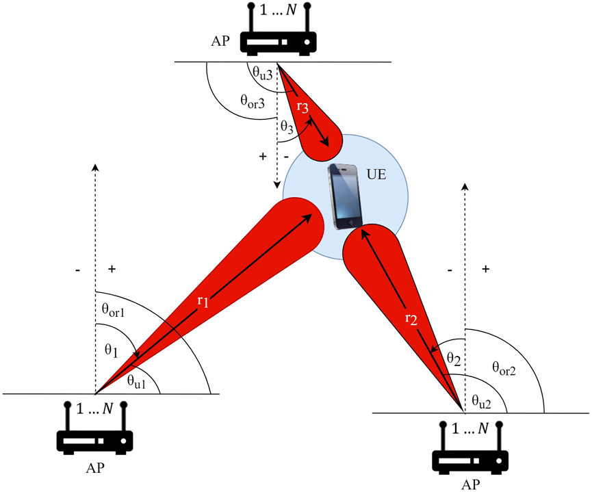
FIGURE 1. System model. The dashed lines depict the orientation of the AP antennas and the positive and negative signs affect only the angle θi.
Adopting the Saleh-Valenzuela model for the THz channel, h can be obtained as Saleh and Valenzuela (1987).
where β(0) and β(i) denote the complex gains of the LoS and non-LoS components, respectively,
where
where Wk ∈ N × N denotes the codebook matrix, with k = 1, … K being the current codebook level.
Tracking reliability parameters
The parameters that affect the reliability of tracking can be divided into two categories, the ones that affect the trajectory tracking resolution (Liu F. et al. (2020); Zhang et al. (2020); Liu X. et al. (2020); Stratidakis et al. (2020a); Chen et al. (2022)) and the ones that affect the angular resolution (Stratidakis et al. (2019); Neema et al. (2021); Gao et al. (2014)), as shown in Figure 2. More specifically, the trajectory tracking resolution refers to the successful trajectory mapping. It is affected by the motion type (e.g. linear or irregular/random), velocity and antenna orientation (if the antenna is directional) of the UE and the tracking estimation frequency
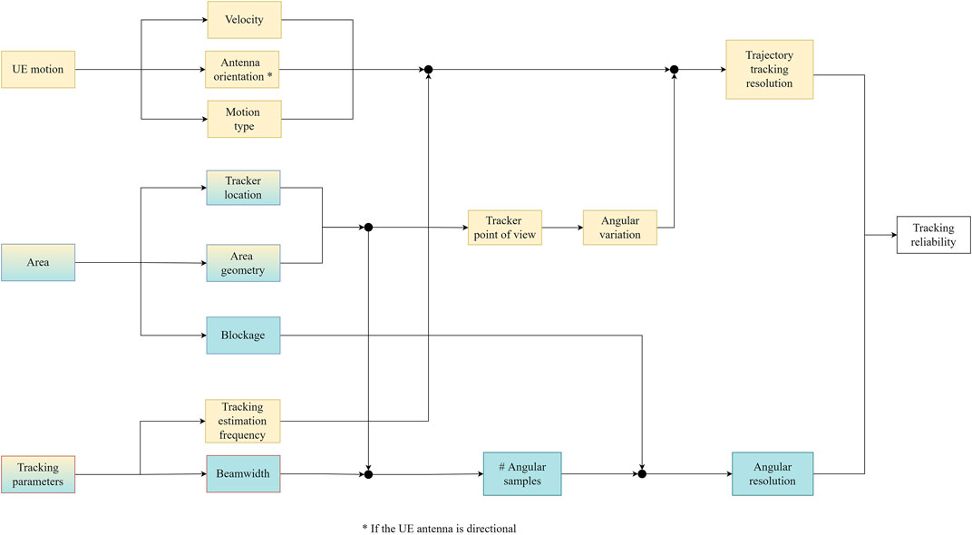
FIGURE 2. Tracking reliability parameters.
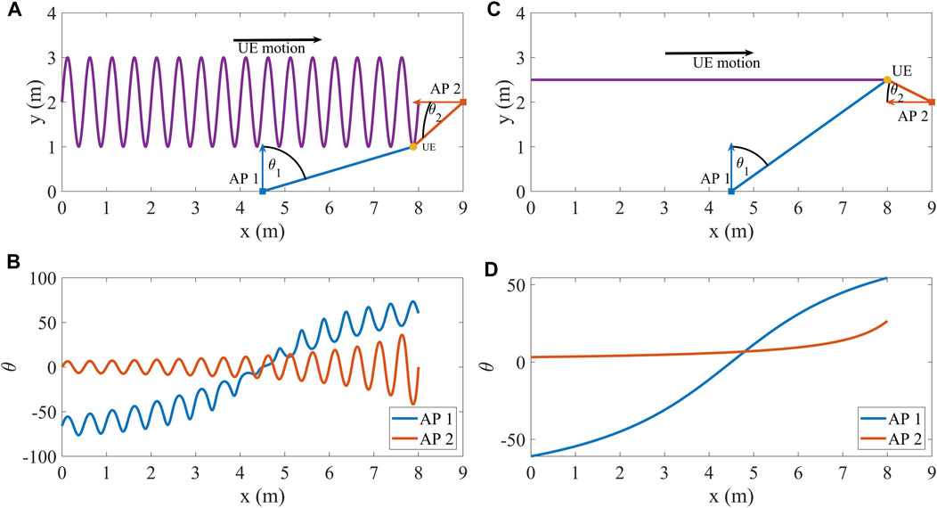
FIGURE 3. AP location point of view regarding the motion of (A,B): UE one and (C,D) UE 2, where the colored arrows denote the antenna orientation of each AP and the black color denotes the general direction of the UE motions.
Proposed method
In this section, a beam-tracking algorithm, that is based on Stratidakis et al. (2019, 2020b), is presented, that makes use of the location estimation performed by multiple cooperating APs, each equipped with an antenna array of N elements and an hierarchical codebook. The increased number of APs placed at different locations takes advantage of each AP’s point of view on the same UE as shown in Figure 3. The hierarchical codebook helps reduce the pilot overhead and the cooperation between the APs helps keep the overhead low, while increasing the probability of successful tracking even when some links are blocked. In the first three timeslots, the algorithm performs an hierarchical search to find the direction of the UE with low power overhead, and then uses a ranging method to find the AP-UE distance in order to estimate the UE location. In the next timeslots, each AP predicts the next UE location based on the estimations of the three previous timeslots and uses a small number of codebook levels each with a small number of codewords to track the UE with low pilot overhead. Furthermore, in each timeslot the APs send their location estimations to a common node that combines the location estimations of all the APs to make a common prediction of the next UE location. The common prediction is only used by an AP that failed to find the UE, so it can continue tracking with low pilot overhead. The algorithm can be divided into two phases, the initialization and the beam-tracking phase.
Initialization
The initialization takes place in the first three timeslots. Note that in order for the algorithm to “break out” of the initialization phase, the estimations in all three timeslots must be successful.
1. Hierarchical search: The AP performs an hierarchical search by alternating between two codewords of each codebook level. As the codebook follows a binary-tree structure, the first codebook level can be skipped in favor of the entire second level that offers higher gain without increasing the pilot overhead. The AP finds the general direction of the UE using the 4 codewords of the second level. Then it refines the estimation with the 1-level higher codebook level and alternating between the two codewords that correspond to the “branch” of the selected lower level codeword. The AP continues to refine the estimation with higher level codewords until the last codebook level. More specifically, with the second codebook level, the ith AP estimates the beamspace channel
assuming that the number of pilots, NP, is even, where
Then the AP must estimate the non-zero elements of
2. Ranging: The AP estimates the AP-UE distance using a two-way ranging method (e.g. Guo et al. (2019)) as
where i = 1, … , M denotes the ith AP, ri is the actual AP-UE distance between the ith AP and the UE, and ei is a normally distributed random variable with zero mean and standard deviation σe Kim and Kim (2010).
3. Location estimation: With the knowledge of both the direction and distance of the UE in relation to the AP, the location of the UE can be easily estimated as
where x and y stand for the coordinates of the UE location and
where θi is the main lobe direction of the highest level codeword of the ith AP with which the direction of the UE was estimated and θor is the angle between the x-axis and the ith AP antenna orientation.
4. Cooperation: After obtaining the location of the UE, all the APs send the information to a common node in order to make a common estimation using the center of gravity of all the estimations.
Beam-tracking
The beam-tracking takes place after three consecutive successful estimations of the angle UE location.
5. Location prediction: The APs predict the location of the UE in the next timeslot assuming a linear motion.
6. Direction estimation: Then, the AP uses the second highest codebook level to track the UE by alternating between 4 codewords that generate beams around and towards the direction of the prediction. In order to find the suitable codeword, the AP must detect the support of
7. Refinement: The estimation is then refined by alternating between the 2 codewords of the last codebook level that belong to the branch of the codeword of the second highest level as in the Hierarchical search of the initialization. The use of multiple codebook levels in this step increases the robustness of the algorithm, in cases of non-linear motions and non-constant speed, while keeping the pilot overhead low.
8. Ranging, location estimation and cooperation: After obtaining the angle θi, the AP performs the ranging, location estimation and cooperation as in the initialization.
Algorithm 1. Proposed Algorithm.

Simulation results
In this section, the effectiveness of the proposed approach is evaluated in terms of probability of success and average number of pilots. Probability of success is the probability of at least one AP successfully tracking the UE in all motions, timeslots and number of APs. The average number of pilots is estimated over all motions, timeslots and number of APs. The results are derived by means of Monte-Carlo simulations in 3,000 different motions generated by the random motion generation used in Stratidakis et al. (2020a). Specifically, the random motion consists of random walk with a step of 2 m and interpolation with frequency QI, that simulates the tracking estimation frequency
Tracking estimation frequency
The tracking estimation frequency,
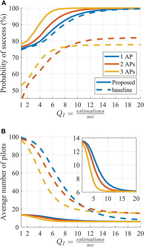
FIGURE 4. Performance of the proposed beam-tracking method under different estimation frequencies, QI. (A): Probability of successful tracking per number of tracker APs. (B): Average number of pilots per timeslot for different number of tracker APs.
In Figure 5, the minimum MSE, is presented as a function of the tracking estimation frequency, QI. The minimum MSE is calculated as
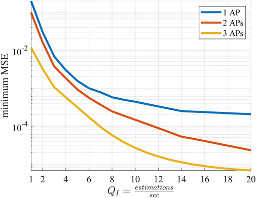
FIGURE 5. Minimum MSE under different estimation frequencies, QI.
Blockage
Blockage is another significant parameter that can make a tracking attempt fail as it can reduce the received power to zero. Note that, only the case of total blockage is studied in this paper. With only one AP if the link is blocked the tracking either cannot continue and the algorithm has to restart, or continue with reduced prediction accuracy. With multiple APs, and a common location estimation, even when a link is blocked the algorithm on than AP does not need to restart. Therefore, it can keep using the prediction and continue tracking the UE with low pilot overhead. The basic requirement is for at least one AP to be able to track the UE in every timeslot, even if it is not the same everytime. As an example, in Table 1, the probability of success and average number of pilots are presented for 4 cases of blockage probability, Pb. The 4 cases are 0% in all AP-UE links, 50% in one AP-UE link, 50% in two AP-UE links and 50% in three AP-UE links. The tracking estimation frequency QI is 15 and the blocked link is random in every timeslot. In Table 1 the probability of success in tracking the UE is shown, while in Table 1 the average number of pilots per timeslot is presented. With one AP, when Pb = 0%, the probability of success is 99.2%, while when Pb = 50%, it is 74%. The corresponding average number of pilots is 6.3 with Pb = 0% and 12.5 with Pb = 50%. With two APs, when Pb = 0%, the probability of success is 99.8%, when Pb = 50% on one AP-UE link it is 98% and when Pb = 50% on two AP-UE links it is 80.8% with average number of pilots 6.14, 6.7 and 11.5 respectively. With three APs, the probability of success without blockage is 100%, when Pb = 50% on one AP-UE link it is 99.8%, when Pb = 50% on two AP-UE links it is 98% and when Pb = 50% on three AP-UE links it is 90%. The respective average number of pilots is 6.1, 6.14, 6.7 and 8.9. It can be observed that with Pb = 50% on all APs, the higher the number of APs, the higher the probability of success and the lower the pilot overhead. In this case, the difference in probability of success between using one and three APs to track the UE is 16% and the difference in average number of pilots is 3.6.
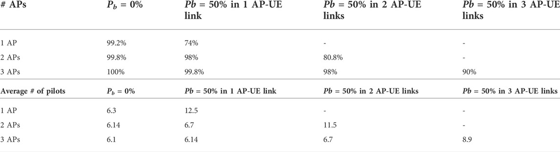
TABLE 1. A: Probability of success and B: Average number of pilots in links with fixed probability of blockage in each timeslot. The blocked link is random in every timeslot.
Discussion
The results can be further improved with additional APs, but at the expense of increasing cost. One promising solution to the cost of multiple APs is the use of reconfigurable intelligent surfaces (RISs). RISs require less energy to operate as they simply redirect the signal transmitted by the AP towards the UE instead of re-transmitting it. Furthermore, RISs do not amplify the existing AWGN like the amplify-and-forward relays, and lack the delay of decode-and-forward relays Boulogeorgos and Alexiou (2020); Bjornson et al. (2020). As with the APs, the RISs would offer different points of view and increase the probability of success, especially in the presence of blockage. However, an RIS is not autonomous and requires a transmitter to function, which means that the AP must track the UE once directly and once through the RIS. Localization can help reduce or even avoid this unnecessary tracking overhead, depending on its accuracy.
Conclusion
In this paper, the parameters that affect the reliability of tracking are presented and divided into two categories, the trajectory tracking resolution and the angular resolution. The trajectory tracking resolution contains the parameters that affect the prediction of the tracking algorithms and the angular resolution contains the parameters that affect successful estimation in each timeslot. Furthermore, a beam-tracking method is proposed to address the challenges of the two categories. The proposed method makes use of multiple APs and an hierarchical codebook to track the user from different locations with low pilot overhead even when most links are blocked. The performance of this beam-tracking method is measured through Monte-Carlo simulations with the probability of success in tracking the UE, the average number of pilots that was required per timeslot and the MSE as metrics. The simulations are performed for different tracking estimation frequencies and for different number of blocked links. The simulations show a big difference between using a one AP and using two or three APs, especially with low tracking estimation frequency or blockage. In relation to the authors’ previous beam-tracking algorithms, the proposed algorithm is more robust to ranging errors, offers increased probability of successful estimation and reduced required number of pilots under realistic ranging errors especially with multiple APs.
Data availability statement
The original contributions presented in the study are included in the article/supplementary material further inquiries can be directed to the corresponding author.
Author contributions
Conceptualization and Methodology, GS, SD, and AA. Formal Analysis and validations, GS and SD. Simulations and Visualization, GS. Writing—Review and Editing, GS, SD, and AA.
Funding
This work was supported by the European Commission’s Horizon 2020 Research and Innovation Programme under Agreement 871464 (ARIADNE).
Conflict of interest
The authors declare that the research was conducted in the absence of any commercial or financial relationships that could be construed as a potential conflict of interest.
Publisher’s note
All claims expressed in this article are solely those of the authors and do not necessarily represent those of their affiliated organizations, or those of the publisher, the editors and the reviewers. Any product that may be evaluated in this article, or claim that may be made by its manufacturer, is not guaranteed or endorsed by the publisher.
References
Basar, E., Renzo, M. D., Rosny, J. D., Debbah, M., Alouini, M.-S., and Zhang, R. (2019). Wireless communications through reconfigurable intelligent surfaces. IEEE Access 7, 116753–116773. doi:10.1109/access.2019.2935192
Bjornson, E., Ozdogan, O., and Larsson, E. G. (2020). Intelligent reflecting surface versus decode-and-forward: How large surfaces are needed to beat relaying? IEEE Wirel. Commun. Lett. 9, 244–248. doi:10.1109/lwc.2019.2950624
Boulogeorgos, A.-A. A., Alexiou, A., Merkle, T., Schubert, C., Elschner, R., Katsiotis, A., et al. (2018). Terahertz technologies to deliver optical network quality of experience in wireless systems beyond 5G. IEEE Commun. Mag. 56, 144–151. doi:10.1109/mcom.2018.1700890
Boulogeorgos, A.-A. A., and Alexiou, A. (2020). Performance analysis of reconfigurable intelligent surface-assisted wireless systems and comparison with relaying. IEEE Access 8, 94463–94483. doi:10.1109/ACCESS.2020.2995435
Boulogeorgos, A.-A. A., Papasotiriou, E. N., and Alexiou, A. (2019a). Analytical performance assessment of THz wireless systems. IEEE Access 7, 11436–11453. doi:10.1109/ACCESS.2019.2892198
Boulogeorgos, A.-A. A., Papasotiriou, E. N., and Alexiou, A. (2019b). “Analytical performance evaluation of thz wireless fiber extenders,” in IEEE 30th Annual International Symposium on Personal, Indoor and Mobile Radio Communications (PIMRC), 1–6. doi:10.1109/PIMRC.2019.8904434
Chen, Y., Yan, L., Han, C., and Tao, M. (2022). Millidegree-level direction-of-arrival estimation and tracking for terahertz ultra-massive mimo systems. IEEE Trans. Wirel. Commun. 21, 869–883. doi:10.1109/TWC.2021.3100073
Francesco Foglia, M., Clemente, A., and Gonzalez-Jimenez, J. L. (2020). High-gain $D$ -band transmitarrays in standard PCB Technology for beyond-5G communications. IEEE Trans. Antennas Propag. 68, 587–592. doi:10.1109/tap.2019.2938630
Gao, B., Xiao, Z., Zhang, C., Su, L., Jin, D., and Zeng, L. (2014). “Double-link beam tracking against human blockage and device mobility for 60-ghz wlan,” in 2014 IEEE Wireless Communications and Networking Conference (WCNC), 323–328. doi:10.1109/WCNC.2014.6951988
Gao, X., Dai, L., Zhang, Y., Xie, T., Dai, X., and Wang, Z. (2017). Fast channel tracking for terahertz beamspace massive MIMO systems. IEEE Trans. Veh. Technol. 66, 5689–5696. doi:10.1109/tvt.2016.2614994
Guo, G., Chen, R., Ye, F., Peng, X., Liu, Z., and Pan, Y. (2019). Indoor smartphone localization: A hybrid wifi rtt-rss ranging approach. IEEE Access 7, 176767–176781. doi:10.1109/ACCESS.2019.2957753
Jacob, M., Priebe, S., Dickhoff, R., Kleine-Ostmann, T., Schrader, T., and Kurner, T. (2012). Diffraction in mm and sub-mm wave indoor propagation channels. IEEE Trans. Microw. Theory Tech. 60, 833–844. doi:10.1109/tmtt.2011.2178859
Kim, E., and Kim, K. (2010). Distance estimation with weighted least squares for mobile beacon-based localization in wireless sensor networks. IEEE Signal Process. Lett. 17, 559–562. doi:10.1109/lsp.2010.2047169
Kokkoniemi, J., Lehtomäki, J., and Juntti, M. (2021). A line-of-sight channel model for the 100–450 gigahertz frequency band. EURASIP J. Wirel. Commun. Netw. 88, 2021. doi:10.1186/s13638-021-01974-8
Liu, F., Yuan, W., Masouros, C., and Yuan, J. (2020a). Radar-assisted predictive beamforming for vehicular links: Communication served by sensing. IEEE Trans. Wirel. Commun. 19, 7704–7719. doi:10.1109/TWC.2020.3015735
Liu, X., Yu, J., Qi, H., Yang, J., Rong, W., Zhang, X., et al. (2020b). Learning to predict the mobility of users in mobile mmwave networks. IEEE Wirel. Commun. 27, 124–131. doi:10.1109/MWC.001.1900241
MacCartney, G. R., Deng, S., Sun, S., and Rappaport, T. S. (2016). “Millimeter-wave human blockage at 73 GHz with a simple double knife-edge diffraction model and extension for directional antennas,” in IEEE 84th Vehicular Technology Conference (VTC-Fall) (Montreal, QC, Canada: IEEE). doi:10.1109/vtcfall.2016.7881087
Neema, M., Gopi, E. S., and Katoj, P. K. (2021). “User spatial localization for vision aided beam tracking based millimeter wave systems using convolutional neural networks,” in 2021 10th International Conference on Information and Automation for Sustainability (ICIAfS), 7–12. doi:10.1109/ICIAfS52090.2021.9605960
Ning, B., Chen, Z., Tian, Z., Han, C., and Li, S. (2022). A unified 3d beam training and tracking procedure for terahertz communication. IEEE Trans. Wirel. Commun. 21, 2445–2461. doi:10.1109/TWC.2021.3112493
Papasotiriou, E. N., Boulogeorgos, A.-A. A., and Alexiou, A. (2020). Performance analysis of THz wireless systems in the presence of antenna misalignment and phase noise. IEEE Commun. Lett. 1, 1211–1215. doi:10.1109/lcomm.2020.2981336
Papasotiriou, E. N., Kokkoniemi, J., Boulogeorgos, A.-A. A., Lehtomaki, J., Alexiou, A., and Juntti, M. (2018). “A new look to 275 to 400 GHz band: Channel model and performance evaluation,” in IEEE 29th Annual International Symposium on Personal, Indoor and Mobile Radio Communications (PIMRC) (Bologna, Italy: IEEE). doi:10.1109/pimrc.2018.8580934
Priebe, S., Jacob, M., and Kürner, T. (2012). “The impact of antenna directivities on thz indoor channel characteristics,” in 2012 6th European Conference on Antennas and Propagation (EUCAP), 478–482. doi:10.1109/EuCAP.2012.6205849
Saleh, A., and Valenzuela, R. (1987). A statistical model for indoor multipath propagation. IEEE J. Sel. Areas Commun. 5, 128–137. doi:10.1109/JSAC.1987.1146527
Stratidakis, G., Boulogeorgos, A.-A. A., and Alexiou, A. (2019). “A cooperative localization-aided tracking algorithm for THz wireless systems,” in IEEE Wireless Communications and Networking Conference (WCNC), Marrakech, Morocco.
Stratidakis, G., Ntouni, G. D., Boulogeorgos, A. A., Kritharidis, D., and Alexiou, A. (2020a). “A low-overhead hierarchical beam-tracking algorithm for thz wireless systems,” in 2020 European Conference on Networks and Communications (EuCNC), 74–78. doi:10.1109/EuCNC48522.2020.9200946
Stratidakis, G., Papasotiriou, E. N., Konstantinis, H., Boulogeorgos, A.-A. A., and Alexiou, A. (2020b). “Relay-based blockage and antenna misalignment mitigation in THz wireless communications,” in 2020 2nd 6G Wireless Summit (6G SUMMIT) (Levi, Finland: IEEE). doi:10.1109/6gsummit49458.2020.9083750
Xiao, Z., He, T., Xia, P., and Xia, X. (2016). Hierarchical codebook design for beamforming training in millimeter-wave communication. IEEE Trans. Wirel. Commun. 15, 3380–3392. doi:10.1109/TWC.2016.2520930
Keywords: beamforming, beam-tracking, hierarchical codebook, localization, THz wireless
Citation: Stratidakis G, Droulias S and Alexiou A (2022) A beam-tracking framework for THz networks. Front. Comms. Net 3:965336. doi: 10.3389/frcmn.2022.965336
Received: 09 June 2022; Accepted: 01 August 2022;
Published: 25 August 2022.
Edited by:
Ilangko Balasingham, Norwegian University of Science and Technology, NorwayReviewed by:
Nasir Saeed, National University of Technology, PakistanMona Jaber, Queen Mary University of London, United Kingdom
Copyright © 2022 Stratidakis, Droulias and Alexiou. This is an open-access article distributed under the terms of the Creative Commons Attribution License (CC BY). The use, distribution or reproduction in other forums is permitted, provided the original author(s) and the copyright owner(s) are credited and that the original publication in this journal is cited, in accordance with accepted academic practice. No use, distribution or reproduction is permitted which does not comply with these terms.
*Correspondence: Giorgos Stratidakis, Z2lvc3RyYXRAdW5pcGkuZ3I=