 Wai Yan Yong1*
 Andrés Alayón Glazunov1,2
- 1Department of Electrical Engineering, University of Twente, Enschede, Netherlands
- 2Department of Science and Technology, Linköping University, Norrköping, Sweden
The impact of the substrate dielectric material on the performance of a wideband magneto-electric dipole (MED) phased array antenna is systematically studied in this article. Four commercially available dielectric substrates for mmWave applications, i.e., Rogers RO 5880, RO 3003, RO 4350B, and Panasonic Megtron-6, are considered in the design investigation of the proposed MED phased array antenna. First, the influence of the dielectric constant on the operating frequency of the unit cell MED antenna is explored in the broadside direction (θ = 0°). Second, the scanning impedance is assessed at various scanning angles for both E- and H-plane scanning. Finally, the radiation performance of the proposed design of a finite 8 × 8 MED phased array antenna is examined. This study gives a foundational understanding of the impact of dielectric characteristics on the performance of MED phased arrays. The analysis revealed that the MED phased array antenna based on substrates with a higher dielectric constant exhibited a smaller scanning angle than the substrate with a lower dielectric constant. The findings may serve as practical guidelines for selecting the dielectric substrates for the 5G mmWave phased array antenna in order to adapt their design to an application’s specifications.
1 Introduction
Fifth generation (5G) communication systems aim to provide enhanced mobile broadband communication, ultra-reliability, and low latency communications, allowing numerous end-users to access multi-Gigabit-per-second (Gbps) data speeds while utilizing moderate power Rangan et al. (2014); Chen et al. (2022). In order to reach this ambitious goal, the millimeter-wave (mmWave) band has sparked considerable interest because of the broadly available spectrum Rangan et al. (2014); Sadhu et al. (2019). However, mmWave transmissions suffer from increased propagation losses, which can be mitigated by employing array antennas and beamforming technologies Rangan et al. (2014). To this end, numerous array antennas have been proposed for the 5G mmWave band, utilizing transmission line technologies such as conventional waveguides Kim et al. (2014), gap waveguides Yong et al. (2020), and substrate integrated waveguides Wu et al. (2012). Compared to conventional substrate-based antennas, these antennas have demonstrated lower losses. Nonetheless, they typically have a large form factor and are costly to manufacture.
On the other hand, the telecom industry has maintained its preference for substrate-based antennas due to established and cost-effective manufacturing technologies. In addition, designing microwave antennas and other components on dielectric substrates offer miniaturization properties by choosing the proper dielectric constant. On the one hand, the miniaturization feature is vital, particularly for antenna design, as it will greatly lower the design complexity of phased array antennas. For example, phased arrays require an inter-element spacing of approximately 0.5λh Kildal (2015), where λh is the wavelength of the highest desired operating frequency. On the other hand, the use of substrate-based antennas in the mmWave band urges the reduction of dielectric losses. Recently, the review on the development concept of antenna-in-package (AiP) has been presented in order to minimize the losses of dielectric substrate-based antennas operating in the mmWave band Zhang and Mao (2019). The AiP technology allows the transmission lines between the antenna and RF components to be greatly shortened, which in turn decreases the antenna and RF components’ overall losses Zhang and Mao (2019). In addition, active and passive RF components and antennas are integrated into a single PCB to operate simultaneously. It is worthwhile to mention here that in the early stages of AiP development, the low-temperature co-fired ceramics (LTCC) technique was frequently utilized because it provides a low-loss substrate, superior thermal conductivity, and a high level of passive integration Zhang and Mao (2019); Li et al. (2004); Cao et al. (2014). However, LTCC is relatively expensive, making it impractical for many consumer electronics applications. On the contrary, a substantially more cost-effective manufacturing technology known as High density interconnect (HDI) has been proposed in Zhang and Mao (2019). Indeed, HDI enables the AiP to be realized by stacking industry-standard dielectric substrates of different thicknesses, such as FR-4 and Rogers, into single packages.
With the advent of the HDI manufacturing technology, multiple AiP designs have been realized for various applications Kibaroglu et al. (2018a,b); Gu et al. (2021). Most of the reported studies are concerned with implementing AiP for specific functionalities, such as phased array AiP for mmWave 5G communication Kibaroglu et al. (2018a,b); Gu et al. (2021), AiP with circular polarisation for satellite communication (SATCOM) applications Low et al. (2022) or AiP for automotive radar applications Ku et al. (2014). The majority of these works focus on AiP design with the corresponding system performance analysis. The HDI fabrication technology offers indeed a wider range of substrate options. However, a number of constraints, such as mechanical strength and the complexity of antenna design may limit the substrate options in practice Watanabe et al. (2020). Moreover, due to the multilayer stack-up, the dielectric substrate properties are typically variable, with the prepreg dielectric layer and the core dielectric layer having typically different dielectric properties Watanabe et al. (2020). Consequently, antenna and RF engineers need to understand how to adjust the dielectric characteristics of an antenna in order to meet fabrication specifications. Patch antennas are frequently used in phased array designs Kibaroglu et al. (2018b; a). However, patch antennas typically exhibited narrow bandwidth, covering just a part of the 5G mmWave range. To improve the bandwidth performance, a multilayer stack patch antenna can be fed by a modified feeding structure, which will significantly complicate the design Low et al. (2022); Li et al. (2004). On the other hand, a wideband antenna known as the magneto-electric dipole (MED) has been proposed for wireless communication applications Luk and Wong (2006). The MED has been widely employed for LTE 4G applications Zhai et al. (2014) as well as mmWave applications Dai et al. (2021). The MED antenna’s wideband performance can be achieved by a simple L-probe feeding utilizing vias holes and microstrip patches. Hence, the MED is a potentially cost-efficient alternative for designing the mmWave phased array antenna.
Therefore, in this study, we investigate the effects of dielectric substrates on the performance of magneto-electric dipole (MED) phased array antennas. The MED is chosen due to its demonstrated wideband capabilities and identical E- and H-plane radiation patterns, which makes it appropriate for the antenna design of a phased array. In this paper, we focus on the effect of different, commercially available dielectric substrates on the scanning impedance performance of the MED phased array antenna. We consider four commercially available substrates, i.e., the Rogers RO 5880, RO 3003, RO 4350B, and the Panasonic Megtron-6. The present study is completely based on numerical computations with the CST Microwave Studio, by first employing the infinite periodic unit cell boundary condition, where we focus on the design of the unit cell. Next, in order to evaluate the scanning beam performance of the finite array antenna, the open boundary condition is applied to analyze the performance of the 8 × 8 MED phased array. The main contributions of this paper are summarized below.
• The impact of varying the dielectric constant ɛr on the broadside performance of the unit cell MED is evaluated. Our study demonstrated that as the ϵr of the substrates is increased, the overall operating frequency of the antenna will be shifted toward lower frequency band.
• The scanning capability of a MED phased array antenna is evaluated for various dielectric constants ɛr of the four commercially available substrates. First, the scanned impedance of the unit cell MED with infinite periodic boundary conditions in the CST was evaluated. Second, the radiation performance of the infinite 8 × 8 phased array antenna was evaluated using the open boundary condition. From our analysis, the dielectric substrate with lower ϵr offered better scanning performance than the one with higher ϵr, particularly for the H-plane scanning.
• The obtained results offer the antenna designer a foundation for understanding how the dielectric properties of the substrate may affect the phased array antenna performance. We believe that this will in turn considerably facilitate the phased array antenna performance optimization process throughout the design phase.
The remainder of the paper is organized as follows. In Section 2, the scanning performance of an 8 × 8 MED array antenna is presented. In Section 2.1, the MED antenna design and the substrate parameters are provided. Section 2.2 presents the evaluation of the fixed-beam broadside performance of a MED array by varying the dielectric constant while other antenna parameters are fixed. In Section 2.3, the MED antenna is optimized for the considered substrates, and their scanned impedance performance is evaluated. In Section 2.4, the radiation performance of the 8 × 8 finite MED array antenna is presented. Moreover, the discussion of the performance and the fabrication consideration of the MED as well as the method used in the study of this paper are presented in Section 2.5 and Section 2.6, respectively. Lastly, the conclusion of this study is presented in Section 3.
2 Scanning performance of an 8 × 8 MED array antenna
2.1 MED antenna element design and substrate parameters
Let’s first consider the magneto-electric dipole (MED) antenna design focusing on the antenna element of an array radiating at broadside only, i.e., a fixed-beam array. This is also the starting point for the scanning phased array antenna element design. The considered MED antenna is based on the design approach outlined in Li and Luk (2015). The proposed MED antenna element is shown in Figure 1 and consists of four metallic square patches that function as the electric dipoles and the space between the metallic vias that function as the equivalent magnetic dipole. The excitation of the antenna is achieved by an L-probe feed. The design dimension parameters are shown in Figure 1 and their numerical values are tabulated in Table 1. The width and the length are denoted by WMED, and LMED, respectively. The substrate thickness is denoted by Hsub. The width and the length of the dipole patches are given by W1, L1, respectively. L2 denotes the length of the L-probe foot, while g1 and g2 denote the separation distance between the dipole patches as illustrated in Figure 1. The diameter of vias is dvias and the minimum pad size is denoted by gvias.
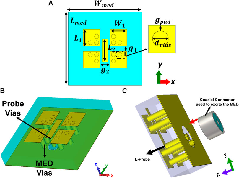
FIGURE 1. An artist of the proposed MED (A) Top View (B) Perspective Top View (C) Perspective Back View.

TABLE 1. The optimized dimensions of the proposed fixed MED antenna based on Rogers RO 5880. All dimensions are in mm.
The unit cell size of the considered MED antenna element is WMED = λcf, where λcf is the wavelength of the center operating frequency considered here, i.e., fcf ≈ 28 GHz. Since the unit cell dimension is large, it thus can only be used for fixed-beam applications where broadside radiation is of interest. Otherwise, grating lobes will appear while scanning.
2.2 Fixed-beam broadside performance with primary MED design
We now investigate the impact of the substrate dielectric constant ɛr on the |S11| ≤ −10 dB bandwidth of the MED antenna element for fixed-beam applications. The considered substrates in this study are the Rogers RO 5880, RO 3003, RO 4350B, and the Panasonic Megtron-6, which electrical and dimensional characteristics are summarized in Table 2. More specifically, we consider 2.2 ≤ ɛr ≤ 3.6, where 2.2 and 3.6 are the dielectric constants of the Rogers 5880 and Rogers 4350 B, respectively. It is worthwhile to note that the dielectric constants of the most commonly used substrates for mmWave applications with low-loss performance typically fall within this range. The computations are done by first optimizing the MED dimensions for the Rogers RO 5880 substrate, which values are shown in Table 1. These values were then kept constant, while ɛr was increased.

TABLE 2. Properties of the considered dielectric substrates.
Figure 2 shows a comparison of the computed reflection coefficient |S11| for the MED antenna element as a function of different dielectric constant values ɛr. As can be seen from Figure 2, increasing the ɛr results in the shift of |S11| toward lower frequencies. This is expected, as the basic theory of microstrip antennas predicts that when the ɛr of the substrates increases, the effective wavelength of the antenna will decrease accordingly, e.g., see Kildal (2015). Another important observation is that increasing ɛr can be exploited to reduce the size of the antenna unit cell with is in line with the study presented in Schaubert et al. (1989). In addition, it is worthwhile to note that increasing or decreasing ɛr by 10%, or about 0.2 in absolute value, will shift the entire operating frequency by approximately 3%, down or up, respectively. Finally, the fractional bandwidth also varies from 43% to 45% as ɛr changes within the considered interval.
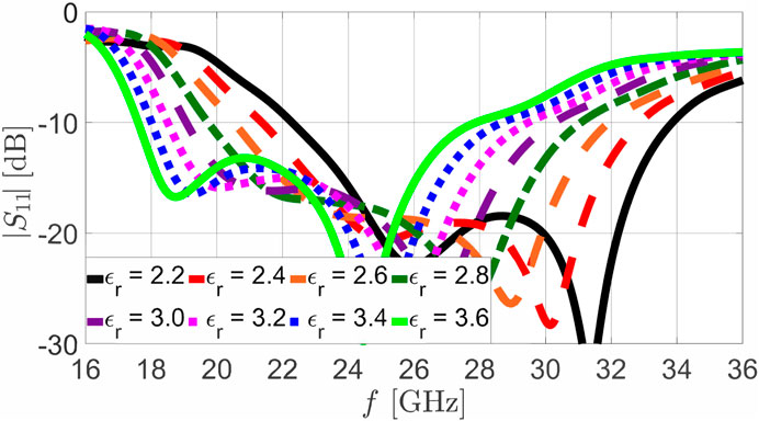
FIGURE 2. Computed reflection coefficient, |S11| as a function of frequency for single element MED operating at broadside direction. Results are shown for various substrates with 2.2≤ ɛr ≤3.6.
2.3 Optimized unit-cell MED antenna element of phased array
Our next step is to use the MED antenna element described above to design a phased array antenna. However, as stated above, the MED antenna dimensions are too large for this purpose. Therefore, the dimensions of the proposed MED are firstly altered by choosing the dimensions satisfying the non-radiating grating lobes condition. Hence, the unit cell dimension of the MED antenna must satisfy the well-known relationship for the inter-element spacing Kildal (2015)
where the λh is the wavelength of the highest operating frequency of interest, i.e., fh ≈ 30 GHz for the targeted design, and θscanning is the scanning angle. Assuming that the non-grating lobes condition for scanning shall be satisfied for θscanning ≤ 60° we use 1 to arrive at the unit cell dimension of WMED = LMED ≈ 0.52λh for all the cases that will be discussed from this point on. In choosing this value we also considered that sufficient room will be left for optimizing the MED unit cell dimension. In addition, we fix the thickness of the MED to Hsub = 1.52 mm in order to give a sufficient fair comparison for all different substrates given in Table 2. Excluding the aforementioned parameters, all the other parameters, i.e., W1, L1, L2, g1 and g2 (see Figure 1) have been optimized to ensure the scanning impedance bandwidth, also known as active impedance. Table 3 tabulated the optimized parameters of the MED antenna for phased array based on different dielectric substrates. The optimization is done to maintain the bandwidth at the broadside to cover the 24–30 GHz band. These values are sufficiently good to provide the adequate scanning performance of the phased array. Nonetheless, optimization of the parameters did also take into account the fabrication tolerances/limitations such as the minimum diameter of vias within dvias ≥ 0.3 mm and a pad size within gpad ≥ 0.1 mm.
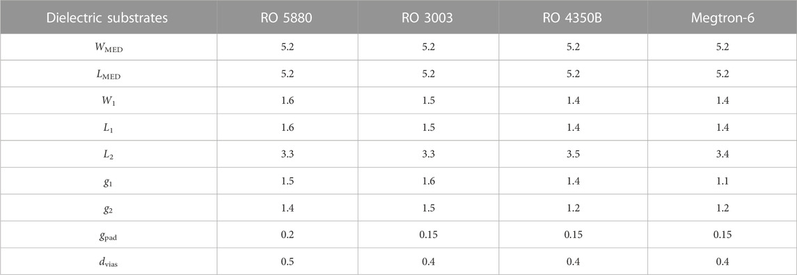
TABLE 3. The optimized dimensions of the proposed MED antenna based on four different substrates for phased array antenna. All dimensions are in mm.
The computed scanning impedances for both E- and H-planes scanning of the proposed unit cell MED antenna are depicted in Figure 3, for Roger 5880, Roger 3003, Roger 4350 B, and Panasonic Megtron-6. The proposed MED phased array antenna is intended to operate from 24–30 GHz with acceptable degradation of the scanning impedance from −10 dB to −7 dB, which is equivalent to an additional 0.5 dB gain drop due to the mismatching caused by beam scanning Hansen (2009). For instance, with scanned impedance of −10 dB, the power loss due to the mismatch is approximately 0.5 dB and is increased to 1 dB when the scanned impedance has deteriorated to −7 dB. The power loss due to the beam scanning mismatching can be computed using mismatch loss, Lmismatch = 1 − |Γ|2, where Γ is the reflection coefficient Pozar (2011). There are several observations regarding the impact of the dielectric substrate on the scanning impedance as follows next. The scanning performance of the MED based on RO 5880 and RO 3003 is generally better than for RO 4350B and Megtron-6. For instance, considering the operating frequency of 24–30 GHz, in the E-plane scanning, the MED based on RO 5880 and RO 3003 can scan up to 60° at S11,scanned ≤ −7 dB, while the MED based on RO 4350B and Megtron-6 can only scan up to 50°. Similar performance is observed for H-plane scanning where MED based on RO 5880 and RO 3003 can scan up to 50°, whereas the MED based on RO 4350B and Megtron-6 can only scan up to 40°. In addition, it is also worthwhile to note that as the dielectric constant of the substrate increases, the lower-end operating frequency (24 GHz) provides better active matching while scanning. This is mainly due to the shifting in the operating frequency which is in line with the earlier observation of the fixed beam MED antenna. For example, considering the −7 dB scanned impedance at scanning angle θ = 40°, the lowest operating frequency is approximately 23.8 GHz for MED based on RO 5880, whereas this lowest frequency for MED based on RO 3003, RO 4350 B and Megtron-6 is approximately 22 GHz. Nevertheless, this shifting is not as significant as it is in broadside, as the mismatching due to the mutual coupling and surface waves will also impact the overall performance of the phased array when the beam is scanned away from the broadside Hansen (2009).
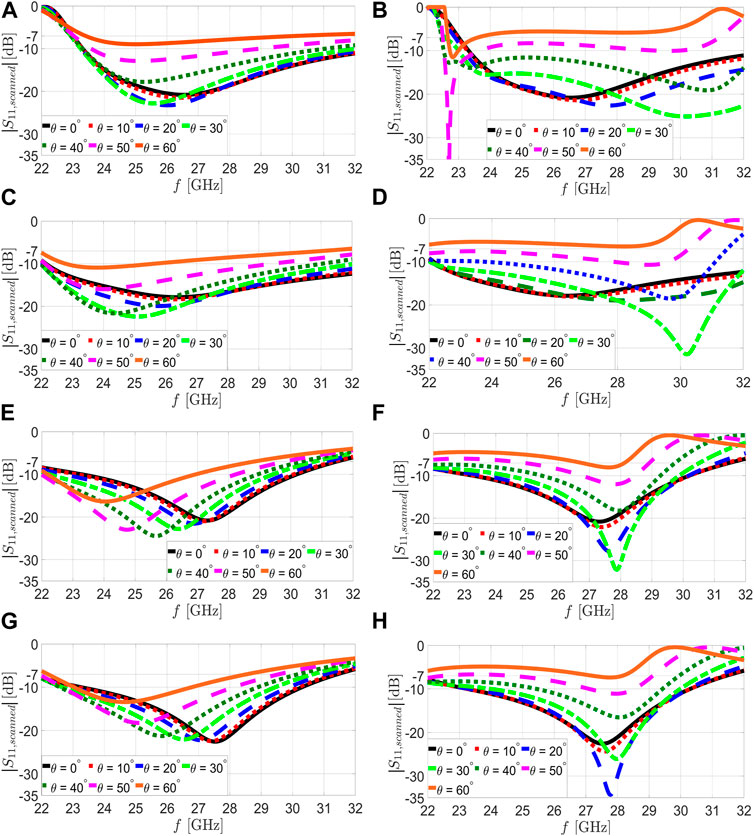
FIGURE 3. Computed scanning impedance S11,scanning of the proposed unit cell MED antenna fed by L-probe as a function of the frequency for different scanning angles θ. Results are depicted for various substrates: Rogers 5880 at the E-plane in (A) and the H-plane in (B), Rogers 3003 at the E-plane in (C) and the H-plane in (D), Rogers 4350B at the E-plane in (E) and the H-plane in (F), and Panasonic Megtron-6 at the E-plane in (G) and the H-plane in (H).
2.4 8 × 8 finite MED array antenna
As well known, the performance of the center elements can be approximated fairly well by an infinite array model. However, in realistic array antennas with a finite number of antenna elements, the edge element patterns, and active reflection coefficients will suffer from inaccuracies due to the asymmetric environment. Therefore, to further investigate the beam scanning performance of the proposed MED phased array antenna based on various dielectric materials, an 8 × 8 finite array antenna, as seen in Figure 4, is simulated in CST Microwave Studio with an open boundary condition. Since the proposed MED antenna was evaluated using the unit cell boundary condition in the previous investigation, for finite array antenna, to minimize the undesirable edge effects, an additional row/column of dummy elements is added to each side of the 8 × 8 array layout.
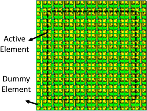
FIGURE 4. An artist representation of the proposed 8×8 MED array antenna. The MED antennas inside the black dotted box are the radiating elements, i.e., the active antenna elements, while those outside the black dotted box are the dummy antenna elements or passive antenna elements.
Figure 5 shows the computed radiation pattern of the proposed 8 × 8 MED phased array antennas at 24 GHz (lower end of the targeted operating frequency) and 30 GHz (higher end of the targeted operating frequency) based on various types of dielectric substrates as explained in the figure caption. Results are provided for scanning in the E- and the H-plane. There are several relevant observations that can be drawn from the computed radiation patterns. First, taking into account a 3 dB loss in gain when the radiation beam is scanned away from the broadside direction, the considered MED phased array exhibits better scanning performance at the E-plane than at the H-plane for all substrates. It is worthwhile noting that this effect is more significant at the 30 GHz than at 24 GHz. This is explained by the fact that the wavelength at 30 GHz is closer to the maximum allowed inter-element distance avoiding the appearance of grating lobes given by 1. This results in a more significant mismatching of the phased array antenna impedance. This finding is consistent with the conclusion based on the computed scanning impedance of the MED unit cell phased array shown in Figure 3. Indeed, a better scanning impedance matching is achieved for the E-plane scanning as compared to the H-plane scanning of the proposed MED phased array antenna. Second, the scanning performance of the MED phased array antennas based on the RO 5880 and the RO 3003 are comparable. The MED phased array antenna based on these substrates could typically deliver full scanning, i.e., up to ±60°, for the E-plane and up to approximately ±50° for the H-plane. It is important to note that, for the H-plane scanning when the beam is scanned up to ±60°, although the gain drop is larger than 3 dB in both cases, the MED phased array antenna based on RO 3003 exhibits a more substantial drop in gain compared to the one based on RO 5880. This is due to the more significant mismatching in the scanning impedance of the RO 3003 MED phased array antenna, as demonstrated in the unit cell evaluation in Figure 3. On the other hand, the scanning performances of the MED phased array based on RO 4350 B and Megtron-6 are comparable. Scanning up to ±50° and ±40° are possible for the E- and H-planes, respectively, with a gain drop of less than 3 dB. This observation of the scanning performance is consistent with the assessment of the scanning impedance of the MED phased array antenna unit cell evaluated with the infinite boundary condition.
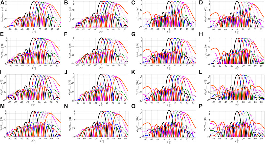
FIGURE 5. Computed normalized radiation patterns for E- and H-planes scanning at 24 GHz and 30 GHz for the 8×8 MED array antenna based on various substrates. Rogers 5880 at 24 GHz for the E-plane in (A) and the H-plane in (B), Rogers 5880 at 30 GHz for the E-plane in (C) and the H-plane in (D), Rogers 3003 at 24 GHz for the E-plane in (E) and the H-plane in (F), Rogers 3003 at 30 GHz for the E-plane in (G) and the H-plane in (H), Rogers 4350B at 24 GHz for the E-plane in (I) and the H-plane in (J), Rogers 4350B at 30 GHz for the E-plane in (K) and the H-plane in (L), and Panasonic Megtron-6 at 24 GHz for the E-plane in (M) and the H-plane in (N), and Panasonic Megtron-6 at 30 GHz for the E-plane in (O) and the H-plane in (P).
In addition, another key parameter of the radiation performance of the phased array antenna is the side lobe levels (SLLs). To attempt a fair comparison for all the considered substrates, we fixed the larger scanning angle to 50° and 40° for E- and H-planes, respectively. It is worth noting that, in the broadside direction, the SLLs of the proposed MED antenna for all considered substrates are as low as −13 dB. Nevertheless, when the beam is scanned away from the broadside, an intriguing observation can be made. Firstly, at the lower-end frequency (24 GHz), the SLLs for the MED based on RO 4350B and Megtron-6 are approximately equal to −11.3dB, which are generally better than the MED based on RO 5880 and RO 3003, with SLLs approximately −11 dB. This effect can be explained by the better matching at the lower-end frequency due to the shifting of operating frequency as the result of the increase of dielectric constant as aforementioned. On the other hand, at the higher-end operating frequency (30 GHz), the SLLs for the MED based on RO 5880 and RO 3003 are generally better than the MED based on RO 4350B and Megtron-6. The SLLs for E-plane scanning are approximately −11.0 dB, −10.9 dB, −10.5 dB and −10.6 dB for RO 5880, RO 3003, RO 4350B, and Megtron-6, respectively. Moreover, the SLLs for H-plane scanning are approximately −12.0dB, −11.8 dB, −10.6 dB, and −11.1 dB for RO 5880, RO 3003, RO 4350B, and Megtron-6, respectively. This result can be explained by the surface waves in the dielectric materials. The cutoff frequency of the excitation of the surface wave shifts toward lower frequencies as the dielectric permittivity increases Horsfield and Ball (2000). Therefore, for a fixed dimension of the unit cell MED antenna, the surface wave propagating in a dielectric substrate with a higher dielectric permittivity value will appear at a smaller scanning angle as compared to the MED antenna based on lower dielectric permittivity, reducing the beam scanning capability of the MED phased array antenna.
Figure 6 shows the computed gain and the maximum cross-polarization level X − Pol based on different dielectric substrates for broadside and scanning angle θ = 60° degrees at E- and H-planes, respectively. As can be seen from Fig.- 6, the array antenna gains of the proposed MED phased array based on the various dielectric substrates are comparable to each other. The minor difference observed is primarily caused by the different dielectric losses of the materials. Nonetheless, when the antenna beam is scanned away from the broadside to θ = 60° in both the E- and H-planes, the computed gain performance varies significantly at the higher end of the operating frequencies depending on the dielectric substrate. This fluctuation in the computed gain at the higher operating frequencies of the proposed MED phased array is mainly caused by mismatching in the scanning impedances, as discussed above. Furthermore, the relative cross-polarization level is sufficiently low in the broadside direction and E-plane scanning for all substrates. However, the level of cross-polarization for H-planes at θ = 60° is high. This is primarily due to the fact that the proposed MED does not perform properly at θ = 60° for the H-plane, as revealed in the scanning impedance study presented above.
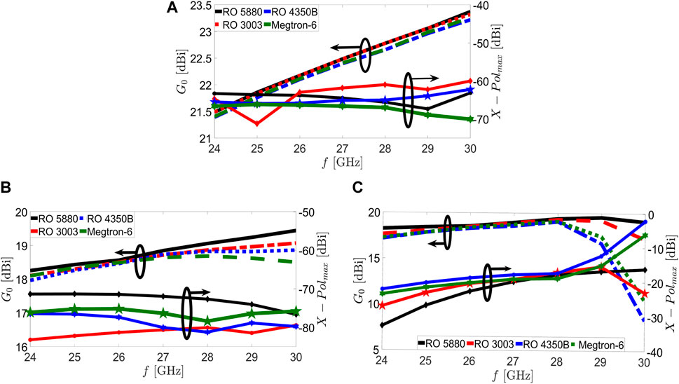
FIGURE 6. Computed G0 and maximum relative cross-polarisation level X − Pol level at broadide (A) as well as θ =60° for the E-planne scanning (B) and the H-plane (C) scanning for the proposed 8×8 MED phased array antenna based on various dielectric substrates.
2.5 Discussion
The performance evaluation of the MED phased array antenna based on the considered dielectric substrates discussed earlier is summarized in Table 4. In addition to the scanning performance, the manufacturability of the proposed MED antenna for the mmWave band is a significant factor. As previously stated, the AiP is preferable for minimizing transmission line losses because it allows both active and passive RF components to be incorporated into a single package with minimal transmission line lengths. Although designing the AiP is not the primary objective of this research, the manufacturability of the proposed MED antenna as an AiP integration solution should be investigated in the future. Despite RO 5880 providing the most promising overall performance, in theory, this substrate type is generally unsuitable for AiP development. This is mostly due to the fact that the RO 5880 is composed of glass microfibre reinforced PTFE composites ro5 (2022). The fundamental issue with these substrates is that they are very flexible and can be easily bent when multilayer stack-up designs such as AiP are considered, causing them to break effortlessly ro5 (2022); Chou et al. (2021). Although this sort of substrate has been extensively proposed in academic research for mmWave applications due to its exceptional performance, it is too expensive for large-scale fabrication, making it unfavorable to industry applications Chou et al. (2021). On the other hand, dielectric substrates with strong mechanical properties, such as the RO 3003, RO 4350, and Panasonic Megtron-6 are being examined. RO 3003 is a low-loss low-dielectric constant substrate and, as demonstrated here, a scanning performance close to that of RO 5880; however, it is typically a more expensive one. Apart from that, the RO 4350 and Panasonic Megtron-6 substrates, which can be manufactured at a lower cost, are considered the most favorable solutions by the majority of the industry Chou et al. (2021). Nonetheless, future research should address improving the scanning performance of the MED phased array developed on these substrates.
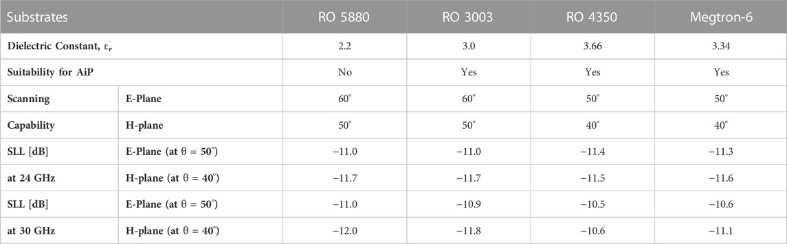
TABLE 4. Comparison of the Scanning Capability of the proposed Unit Cell MED with various dielectric substrates with scanning impedance, S11,scanning ≤−7 dB.
2.6 Method
The Computer Simulation Technology (CST) Microwave Studio was utilized for all computations of the proposed MED phased array antenna. There were two distinct boundary conditions that were applied. Firstly, the infinite unit cell with periodic boundary conditions is utilized to simulate the unit cell MED phased array. The scanning impedance at various scanning angles for the E- and H-planes was obtained from frequency domain simulations in CST. To analyze the scanning performance of the finite 8 × 8 MED phased array antenna, the open boundary condition of the CST is utilized with the time domain simulation. Moreover, to speed up the simulation, the acceleration token in the CST was employed for finite array simulation. It is worth noting that this acceleration token is only applicable for time domain simulation.
All the simulations were completed using the radio system group server at the University of Twente. The server is installed with the NVIDIA-Tesla-P100-16 GB which is one of the essential components to activate the acceleration token.
3 Conclusion
Phased array antennas are becoming a fundamental enabling component of the 5G millimeter wave (mmWave) communication infrastructure. However, the selection of the dielectric substrate will have a substantial effect on the performance of the phased array antenna. The presented study provides guidelines for evaluating the impact of dielectric characteristics on the performances of phased array antennas, which we have performed on the example of magneto-electric dipole (MED) antenna elements. The following is a summary of the key findings of the presented studies.
1. For the considered unit cell MED antenna operating at broadside direction (θ = 0°), it was observed that a 10% variation of the dielectric permittivity ϵr will result in the shifting of the entire operating frequencies by a factor of approximately 3%. The resulting fractional bandwidth also varies from 43–45%.
2. Increasing the dielectric permittivity ϵr resulted in a shift of the operating frequency of the MED antenna toward lower frequencies. Hence, using substrates with a higher dielectric permittivity facilitates miniaturization.
3. The achievable antenna gain G0 at the broadside radiation is comparable for all the considered substrates. However, a minor variance is still found as the loss performance of these dielectric substrates varies. However, as the beam is scanned away from the broadside, the achievable G0 depends on the scanning impedance of the MED phased array antenna.
4. The side lobe levels (SLLs), at broadside direction, are comparable for all the considered substrates. However, when the beam is scanned away from the broadside, at a lower end frequency, the SLLs for the MED phased array with higher dielectric constant performance are slightly better than the MED phased array antenna with a lower dielectric constant. This can be explained with a better matching due to the shifting of the operating frequency toward the lower frequency as the dielectric constant increased. However, as for the higher-end frequency, the SLLs for the RO 5880 and RO 3003 substrates are significantly better than for the phased arrays based on RO 4350B and Megtron-6 MED. This can be explained by the mismatching in the scanned impedance and propagation of surface waves for the substrates with higher dielectric constant.
5. The scanning performance, i.e., the computed scanning impedance and computed radiation patterns, of the MED phased arrays employing the RO5880 and RO 3003 are rather close to each other. Scanning angles up to θ = 60° and θ = 50° for E- and H-planes can be achieved, respectively. In contrast, the scanning performance of the MEDs based on the RO 4350B and Megtron-6 are identical to each other, with the E-plane scanning up to θ = 50° and H-plane scanning up θ = 40°. Therefore, it can be concluded that the MED phased array antenna based on the substrates with a lower dielectric constant generally could provide a better scanning performance than the one with a higher dielectric constant. Nevertheless, this performance improvement also comes with higher fabrication costs. Therefore, depending on the requirements of the application, there is a need for a trade-off between the cost and the performance that need to be considered in the design process.
Future work will focus on merging the considered MED antenna with the active beamformer to develop the phased array antenna for an antenna-in-package (AiP) design. In addition, the realization of the phased array AiP will necessitate further examination of the mechanical factors only briefly described in this paper, such as bending effects and manufacturing faults, to determine how these would impact the performance of the phased array AiP.
Data availability statement
The original contributions presented in the study are included in the article/supplementary material, further inquiries can be directed to the corresponding author.
Author contributions
WYY proposed designs and evaluates the MED phased array antenna based on various types of substrates. AAG proposed evaluating the MED phased array antenna based on various substrates. All authors contributed to the article and approved the submitted version.
Funding
This project has received funding from the European Union’s Horizon 2020 research and innovation program under the Marie Sklodowska-Curie grant agreement No. 766231—WAVECOMBE—H2020-MSCA-ITN-2017.
Conflict of interest
The authors declare that the research was conducted in the absence of any commercial or financial relationships that could be construed as a potential conflict of interest.
Publisher’s note
All claims expressed in this article are solely those of the authors and do not necessarily represent those of their affiliated organizations, or those of the publisher, the editors and the reviewers. Any product that may be evaluated in this article, or claim that may be made by its manufacturer, is not guaranteed or endorsed by the publisher.
References
Cao, B., Wang, H., Huang, Y., Wang, J., and Xu, H. (2014). A novel antenna-in-package with LTCC technology for W-band application. IEEE Antennas Wirel. Propag. Lett. 13, 357–360. doi:10.1109/lawp.2014.2306435
Chen, S., Lu, N., Sun, J., Zhou, C., Li, C., and Wu, D. (2022). High-Isolation wideband MIMO antenna with offset T-Shaped slots for 5G/WLAN applications. Front. Phys. 10, 770. doi:10.3389/fphy.2022.986558
Chou, H. T., Lin, Z. H., Lin, D. B., Yang, C. S., Shen, P. Z., and Pan, C. L. (2021). Considerations of dielectric property deviation and mechanical limitations for antenna-in-package fabrication by SiP-based stacked organic dielectric substrates at millimeter-wave frequencies. IEEE Trans. Antennas Propag. 70, 1309–1319. doi:10.1109/tap.2021.3111340
Dai, X., Li, A., and Luk, K. M. (2021). A wideband compact magnetoelectric dipole antenna fed by sicl for millimeter wave applications. IEEE Trans. Antennas Propag. 69, 5278–5285. doi:10.1109/tap.2021.3060146
Gu, X., Liu, D., Hasegawa, Y., Masuko, K., Baks, C., Suto, Y., et al. (2021). Antenna-in-package integration for a wideband scalable 5G millimeter-wave phased-array module. IEEE Microw. Wirel. Components Lett. 31, 682–684. doi:10.1109/lmwc.2021.3071917
Horsfield, B., and Ball, J. A. (2000). Surface-wave propagation on a grounded dielectric slab covered by a high-permittivity material. IEEE Microw. Guid. wave Lett. 10, 171–173. doi:10.1109/75.850367
Kibaroglu, K., Sayginer, M., Phelps, T., and Rebeiz, G. M. (2018b). A 64-element 28-GHz phased-array transceiver with 52-dBm EIRP and 8–12-Gb/s 5G link at 300 meters without any calibration. IEEE Trans. Microw. Theory Tech. 66, 5796–5811. doi:10.1109/tmtt.2018.2854174
Kibaroglu, K., Sayginer, M., and Rebeiz, G. M. (2018a). A low-cost scalable 32-element 28-GHz phased array transceiver for 5G communication links based on a <inline-formula> <tex-math notation=LaTeX>$2\times 2$ </tex-math> </inline-formula> beamformer flip-chip unit cell. IEEE J. Solid-State Circuits 53, 1260–1274. doi:10.1109/jssc.2018.2791481
Kildal, P. S. (2015). Foundations of antenna engineering: A unified approach for line-of-sight and multipath. Sweden: Artech House.
Kim, D., Hirokawa, J., Ando, M., Takeuchi, J., and Hirata, A. (2014). 64$\,\times\,$64-Element and 32$\,\times\,$32-element slot array antennas using double-layer hollow-waveguide corporate-feed in the 120 GHz band. IEEE Trans. Antennas Propag. 62, 1507–1512. doi:10.1109/TAP.2013.2296318
Ku, B. H., Schmalenberg, P., Inac, O., Gurbuz, O. D., Lee, J. S., Shiozaki, K., et al. (2014). A 77–81-GHz 16-element phased-array receiver with $\pm {\hbox{50}}^{\circ}$ beam scanning for advanced automotive radars. IEEE Trans. Microw. Theory Tech. 62, 2823–2832. doi:10.1109/tmtt.2014.2354134
Li, M., and Luk, K. M. (2015). Wideband magneto-electric dipole antenna for 60-GHz millimeter-wave communications. IEEE Trans. Antennas Propag. 63, 3276–3279. doi:10.1109/tap.2015.2425418
Li, R., DeJean, G., Maeng, M., Lim, K., Pinel, S., Tentzeris, M. M., et al. (2004). Design of compact stacked-patch antennas in LTCC multilayer packaging modules for wireless applications. IEEE Trans. Adv. Packag. 27, 581–589. doi:10.1109/tadvp.2004.831866
Low, K. K. W., Zihir, S., Kanar, T., and Rebeiz, G. M. (2022). A 27–31-GHz 1024-element ka-band SATCOM phased-array transmitter with 49.5-dBW peak EIRP, 1-dB AR, and±70° beam scanning. IEEE Trans. Microw. Theory Tech. 70, 1757–1768. doi:10.1109/tmtt.2021.3139911
Luk, K. M., and Wong, H. (2006). A new wideband unidirectional antenna element. Int. J. Microw. Opt. Technol. 1, 35–44.
Rangan, S., Rappaport, T. S., and Erkip, E. (2014). Millimeter-wave cellular wireless networks: Potentials and challenges. Proc. IEEE 102, 366–385. doi:10.1109/jproc.2014.2299397
RT/duroid (2022). RT/duroid 5870/5880 high frequency laminates. Chandler, Arizona: Rogers Corporation, 1603 080822. Rev.
Sadhu, B., Gu, X., and Valdes-Garcia, A. (2019). The more (antennas), the merrier: A survey of silicon-based mm-wave phased arrays using multi-IC scaling. IEEE Microw. Mag. 20, 32–50. doi:10.1109/mmm.2019.2941632
Schaubert, D. H., Pozar, D. M., and Adrian, A. (1989). Effect of microstrip antenna substrate thickness and permittivity: Comparison of theories with experiment. IEEE Trans. Antennas Propag. 37, 677–682. doi:10.1109/8.29353
Watanabe, A. O., Ali, M., Sayeed, S. Y. B., Tummala, R. R., and Pulugurtha, M. R. (2020). A review of 5G front-end systems package integration. IEEE Trans. Components, Packag. Manuf. Technol. 11, 118–133. doi:10.1109/tcpmt.2020.3041412
Wu, K., Cheng, Y. J., Djerafi, T., and Hong, W. (2012). Substrate-integrated millimeter-wave and terahertz antenna technology. Proc. IEEE 100, 2219–2232. doi:10.1109/jproc.2012.2190252
Yong, W. Y., Haddadi, A., Emanuelsson, T., and Glazunov, A. A. (2020). A bandwidth-enhanced cavity-backed slot array antenna for mmwave fixed-beam applications. IEEE Antennas Wirel. Propag. Lett. 19, 1924–1928. doi:10.1109/lawp.2020.3022988
Zhai, H., Zhang, J., Zang, Y., Gao, Q., and Liang, C. (2014). An LTE base-station magnetoelectric dipole antenna with anti-interference characteristics and its MIMO system application. IEEE Antennas Wirel. Propag. Lett. 14, 906–909. doi:10.1109/lawp.2014.2384519
Keywords: fifth generation (5G), dielectric properties, millimeter-wave (mmwave), ME-dipole, phased array antenna
Citation: Yong WY and Alayón Glazunov A (2023) Impact of dielectric substrate on the performance of an 8 × 8 magneto-electric dipole phased array antenna for 5G mmWave applications. Front. Comms. Net 4:1135941. doi: 10.3389/frcmn.2023.1135941
Received: 02 January 2023; Accepted: 25 May 2023;
Published: 05 June 2023.
Edited by:
HwanSeok Chung, Electronics and Telecommunications Research Institute (ETRI), Republic of KoreaReviewed by:
Ali Khaleghi, Norwegian University of Science and Technology, NorwayTianling Zhang, Xidian University, China
Copyright © 2023 Yong and Alayón Glazunov. This is an open-access article distributed under the terms of the Creative Commons Attribution License (CC BY). The use, distribution or reproduction in other forums is permitted, provided the original author(s) and the copyright owner(s) are credited and that the original publication in this journal is cited, in accordance with accepted academic practice. No use, distribution or reproduction is permitted which does not comply with these terms.
*Correspondence: Wai Yan Yong, dy55Lnlvbmd3YWl5YW5AdXR3ZW50ZS5ubA==