 Tomohiro Amemiya
 Kazuma Aoyama
 Michitaka Hirose
- 1Virtual Reality Educational Research Center, The University of Tokyo, Tokyo, Japan
- 2Graduate School of Information Science and Technology, The University of Tokyo, Tokyo, Japan
- 3Research Center for Advanced Science and Technology, The University of Tokyo, Tokyo, Japan
Binocular parallax provides cues for depth information when a scene is viewed with both eyes. In visual telepresence systems, stereo cameras are commonly used to simulate human eyes. However, motion blur occurs when these cameras are rotated quickly. The use of omnidirectional cameras can reduce the motion blur, but does not provide the correct interpupillary distance (IPD) when viewers tilt or turn their heads sideways. We propose a method called TeleParallax, in which two omnidirectional cameras are separated by the IPD and the direction of the lenses are kept constant in world coordinates by robotic arms during three-dimensional head rotations. TeleParallax can suppress the increase in image buffering during head rotations because each camera can capture an omnidirectional image with the lens direction fixed. We conducted three user studies to evaluate the perceptual effect of head tilt, eye asynchrony, and delays in IPD correction for a particular rotation. The results indicate that TeleParallax can provide depth perception that is independent of the head movement with less visual discomfort. Although the results show that the users were sensitive to the asynchrony between their eyes and to camera motion during IPDs, they retained the feeling of depth perception within interocular delays of 70 ms and motion velocity of 75°/s. These results imply that TeleParallax has remarkable potential for visual telepresence systems.
1 Introduction
Humans and many other primates have two forward-facing eyes and a large overlap between their visual fields (Heesy, 2008). One of the major benefits of this anatomy is the ability to perceive depth because of the slightly different perspectives of the two eyes (binocular disparity). This ability, also known as stereopsis, enables a tangible subjective sensation of three-dimensional (3D) visual space and accurate coding of depth (Vishwanath, 2014; Nityananda and Read, 2017). Human visual systems interpret depth by integrating monocular and binocular depth cues (Bülthoff and Mallot, 1988; Johnston et al., 1993). Among the various cues for perceiving depth, such as binocular disparity, motion parallax, shading, and atmospheric perspective, binocular disparity and occlusion are cues that must be generated by both eyes, and binocular disparity has been reported to be effective at short distances from the eyes (Cutting and Vishton, 1995). Therefore, depth perception, which is generated by binocular disparity within a reachable range, plays an important role in telepresence systems for the visual system, such as monitoring a task in teleoperation Bordas et al. (1996) or teaching surgical skills Votanopoulos et al. (2008).
Stereovision can be achieved using two cameras, one for each eye, if the distance between the two camera lenses, called the baseline, is equal to the interpupillary distance (IPD, the distance between the center of the pupils; Dodgson, 2004) and parallel to both eyes, similar to the human vision system (Baier et al., 2003; Aggarwal et al., 2016). If the two cameras imitate the orientation of the head and the position of the viewer’s eyes, it is possible for the viewer to look around with disparity from different viewpoints in any direction. Some researchers have proposed mounting cameras on a remotely operated robotic actuator (Watanabe et al., 2008; Lanir et al., 2013; Aykut et al., 2017; Wen et al., 2018). However, when the optical axis of each camera lens is rotated to follow the rotation of the viewer’s head, the size of the image buffer is increased because a new image is received at each point of the lens. As a result, the quality of the telepresence experience degrades because of latency and motion blur. To keep the direction of the optical axis of the lens unchanged during head motion, a stereoscopic imaging system using a parallel link mechanism has been proposed (Yanagida et al., 2001). However, even this system produces motion blur when the optical axis of the lens rotates to face a new direction.
Recent off-the-shelf omnidirectional cameras can take 360° photos or videos without the need to rotate the camera. Thus, one way to avoid rotating the optical axis of the lens is to use the omnidirectional camera, which can capture images of the environment from all directions and can change the viewpoint without rotating. Monoscopic omnidirectional cameras, such as Kandao’s QooCam 8K and Ricoh’s Theta series, use two fish-eye lenses on both sides of the camera and stitch the omnidirectional panorama on the device. To construct stereoscopic panoramic vision, side-by-side omnidirectional camera systems, where the baseline of the cameras is identical to the IPD, have been adopted to provide depth cues. However, parallax changes according to the difference between the position of the object and the direction of the camera axis (Matzen et al., 2017).
Omnidirectional camera rigs for multiple (usually wide-angle or fish-eye) stereo pairs arranged in a ring or ball configuration have also been proposed, such as Google’s Jump (Anderson et al., 2016), which consists of sixteen GoPro cameras, Facebook’s Surround 360 cameras, and the Freedom360 GoPro Mount. Multiple stereo pairs were reported to provide an imaging geometry that is inferior to the geometry of evenly distributed cameras with overlapping fields of view facing outward in a ring or ball (Anderson et al., 2016).
We previously proposed TwinCam as a method for moving two omnidirectional cameras in the horizontal plane in conjunction with head movement while taking advantage of the characteristics of global cameras (Tashiro et al., 2017). TwinCam uses a gearing mechanism in which the direction of the optical axes of the lenses of the two focal cameras is fixed in world coordinates even when the camera is moved in response to head movements, thereby reducing the newly generated image buffer and motion blur (Ikei et al., 2019).
However, TwinCam was found to have two main drawbacks. The primary drawback is that the range of movement of the lenses of the two omnidirectional cameras is limited to the horizontal plane, that is, corresponding only to the yaw rotation of the head, leading to failure of stereoscopy during head tilt. When the head is tilted in the roll direction, the baseline of the cameras gets shorter than the IPD of the viewers. It has been reported that head roll, or sideways rotation, is a significant cause of viewer discomfort and adversely affects depth perception in stereoscopic displays (van Ee and Erkelens, 1996; Kane et al., 2012). Thus, when images obtained from stereo cameras with different IPDs are presented on a head-mounted device (HMD), not only do they not feel like a natural space but also head movements can cause intense discomfort and, in the worst case, even nausea and headaches. In addition, if there is no vertical shift in the camera, no vertical disparities occur when the head is tilted. It is reported that vertical disparity affects perceived depth in a parallel stereo cameras configuration (Vienne et al., 2016). Hence, inconsistency of IPD and vertical disparity caused by head tilt is a serious problem for visual telepresence systems.
In addition to the IPD inconsistency problem, the second drawback of TwinCam is that the camera baseline was fixed at 64 mm because the two omnidirectional cameras are connected by a gear mechanism. This interlens distance should be adjustable because IPDs varies across all humans. Depth consistency by maintaining a consistent IPD is important to provide a smooth exploration for visual telepresence systems. However, TwinCam does not provide a consistent IPD for all human observers including children.
In this study, we propose TeleParallax, which uses two multi-axis robotic arms to solve the IPD inconsistency due to head tilt (Figure 1A). In TeleParallax, the omnidirectional camera on the robotic arms rotates without changing the orientation of the camera, to reduce the image blur caused by head motion and provide accurate binocular disparity for 3D head rotation (Figures 1B,C). For ease of explanation, the initial orientation of the camera has coincided with the optical axis of a fisheye lens of the camera in the prototype (Figure 1D). TeleParallax also has the potential to manage individual differences in IPD.
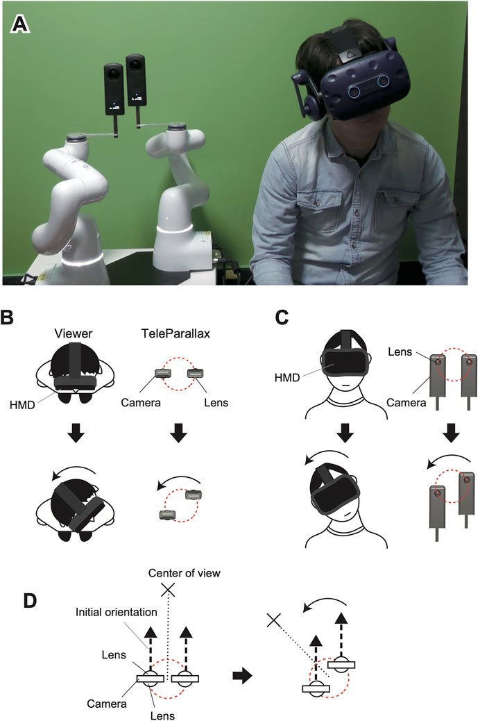
FIGURE 1. TeleParallax system (A). Lens movement according to head rotation in the yaw (B) and roll (C) directions. The initial orientation of the cameras is kept unchanged when the center of view is changed (D).
The remainder of this article is organized as follows. Section 2 describes the mechanism of TeleParallax, in which the distance between the two lenses is kept constant when moved in the same way as the viewer’s head rotate. Its performance is also described. Section 3 describes a psychophysical experiment to investigate whether a viewer can see the binocular parallax using the TeleParallax system. We discuss the experimental results in Section 4 and provide our conclusion in Section 5 with a summary of the study.
2 System
2.1 System Configuration
The lenses of TeleParallax move to keep the camera baseline constant in response to the rotation of the head while fixing the orientation of the lenses in the world coordinate system (Figure 1). Our previous system, the TwinCam system (Tashiro et al., 2017), has two omnidirectional cameras moving around a circumference in the horizontal plane with a diameter of 64 mm. In contrast, TeleParallax has two omnidirectional cameras moving on a spherical surface with a diameter that can be adjusted to the IPD of the viewer. Motion blur is easily caused by conventional stereo camera systems that rotate cameras. One way to reduce motion blur is to move the direction of the optical axis of the lens sufficiently short or slow even when the cameras move or rotate. As shown in Figure 2, the position of each camera is controlled by a multi-axis robotic arm, which determines the distance between the cameras (Amemiya et al., 2021). Even when the head is rotated quickly, the image from the omnidirectional camera has remarkably reduced motion blur compared with the conventional stereo camera systems that rotate cameras, and a 3D image with the correct binocular disparity can be transmitted. We have defined “omnidirectional cameras” as ones that capture an image of the scene 360° around them using one or two image sensors.
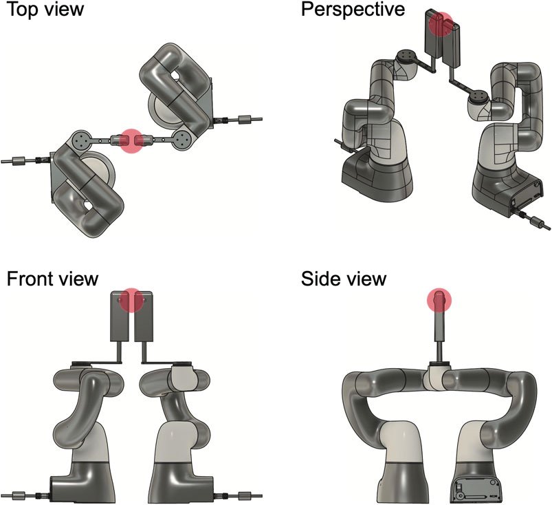
FIGURE 2. Multiview plan of TeleParallax. The red sphere indicates the area of lens motion.
In general, for fixed side-by-side omnidirectional cameras, when the target moves to the extreme right or left, the apparent IPD changes from normal to almost zero. This means that a side-by-side omnidirectional camera system does not provide the correct IPD to a viewer in such directions. In addition, in such systems [e.g., Matzen et al. (2017)], one camera partially occludes the field of view of the other. For example, camera L in Figure 3C occludes the field of view of camera R in the leftmost direction.
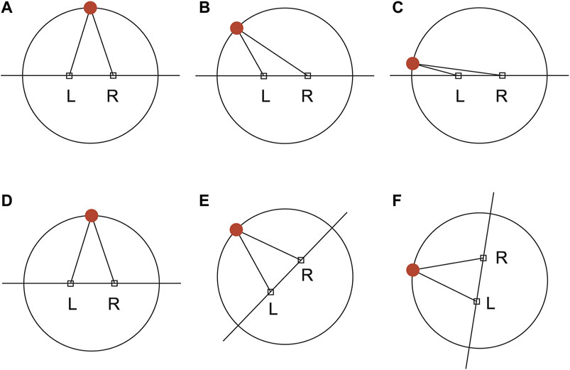
FIGURE 3. Top view of conventional side-by-side omnidirectional cameras (A–C) and our system (D–F). For fixed side-by-side omnidirectional cameras, apparent IPD changes from normal (A) to less than normal (B), and finally to almost zero (C) as the target object moves to the left. In contrast, the orientation of the baseline of the two side-by-side omnidirectional camera cameras in our system changes according to the target position while the lens direction remains unchanged. The apparent IPD is identical for situations (D–F).
In contrast, although the lens direction remains fixed, the orientation of the baseline of the two side-by-side omnidirectional cameras in TeleParallax change according to the target position, as shown in Figures 3D–F. Thus, the apparent IPD is identical for all viewpoints. In addition, the occlusion does not appear in the field of vision because the cameras move so that the normal vector of the baseline faces the target.
Eye–head coupling (e.g., Fang et al. (2015), Freedman (2008), André-Deshays et al. (1991)), tight coupling between saccadic eye movements and attempted head movements, has been demonstrated in animals and humans. In most cases, the directions of the eye and head are aligned, but even if a user is tracking the target only with their eye movements while keeping their head straight, TeleParallax can provide correct binocular images.
Figure 4 shows the data flow of the video transmission and posture information transmission of the TeleParallax system. The delay between rotations of the viewer’s head and camera lens affects the time required to provide the viewer with the correct stereo images. To reduce the delay, we adopt the peer-to-peer (P2P) communication to transmit livestream images obtained from two cameras via WebRTC through Chrome browser in an equirectangular panoramic format (3,840 × 1,920 pixels) without going through a server. Here, we implemented SkyWay (NTT Communications) as the communication platform for WebRTC. The images were received by a Chromium-based embedded browser, which was embedded on the surface of two spherical screens in Unity (2017.4.36f1, Unity Technologies). Two camera objects were located at the center of each spherical screen. The images extracted from the camera objects appeared independently on the left and right displays in the HMD. VP9 codec was selected for compatibility with the Chromium browser.
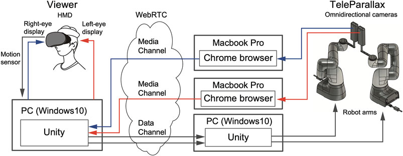
FIGURE 4. System configuration.
Simultaneously, the values of the head posture of the viewer were transmitted over the WebRTC data channel to control the position and posture of the robot arms on which the cameras were mounted. Note that the values of the head posture can be sent directly via TCP communication (b-CAP Communication1) instead of WebRTC when the IP addresses of the robot arms can be specified. The former requires an additional computer and more processing time but is widely available, whereas the latter requires fewer PCs and incurs less delay.
The prototype system is composed of an HMD (HTC Vive Cosmos; FOV: 110°), two omnidirectional cameras (Ricoh THETA Z1), and two robotic arms (Cobotta CVR038A1-NV6-NNN-NNN; DENSO WAVE Corporation). The HMD is connected to a laptop computer (Windows 10 Pro; Intel Core i7-8750H, 2.2 GHz; 32 GB of RAM) with a GeForce GTX 1080. To provide stereovision with the correct IPD, two omnidirectional cameras separated by a fixed baseline were moved, while keeping the direction of the lenses constant in the world coordinates using robotic arms during three-dimensional head rotations. Thus, the width of the omnidirectional cameras must be less than half of the IPD. Considering this criterion, the omnidirectional camera in the prototype system was selected from off-the-shelf omnidirectional cameras as its width was less than half of a representative IPD of 64 mm. Other types of omnidirectional cameras can be used in TeleParallax if the sizes of the cameras are suitable. Each omnidirectional camera was connected to a laptop (MacBook Pro 16 inch, 2019; 2.4 GHz 8-core Intel Core i9, 32 GB of RAM) via USB-C, but there was no synchronization signal for the omnidirectional camera. Each camera was affixed to a robotic arm with six degrees of freedom (DoF) using a custom-made extension link (100 mm) and an extension adapter (Ricoh TE-1), which was mounted on the end of the arm so that the baseline could be extended up to 50 mm. The bottom of the robotic arms was fixed to an aluminum plate. The robot arms have a maximum speed of 1,000 mm/s, a payload of 500 g, and a repetition error of 0.05 mm on all axes. Each robotic arm was connected to a laptop (Windows 10 Home; 2.2 GHz 6-core Intel Core i7-8750H) via Ethernet and controlled via a b-CAP slave mode. Unity was used to control the robotic arms (Figure 4) as well as transmit and receive images.
Figure 5 shows an example of the captured equirectangular images for each eye. The viewer sees the region in the image shown by the red outlined box in Figure 5, as illustrated in Figure 6A. When the viewer’s head moves, he or she will be able to see other regions of the image (i.e., regions outside the red box) without blurring thanks to the panoramas, but the IPD will be incorrect, as shown in Figure 6B. However, the stereo image is slowly updated to the one with the correct binocular disparity by matching the positions of the two cameras with those of the viewer’s eyes, as shown in Figure 6C. The stages of this change in head motion and the IPD are summarized in Figure 6. Note that the center of rotation of TeleParallax is the midpoint between the two cameras. In contrast, the center of rotation of the human head is not between the two eyes.
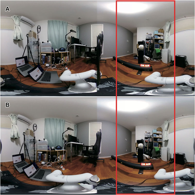
FIGURE 5. Captured images from the left camera (A) and the right camera (B). The red frame shows the area displayed on the HMD, which is the front viewing direction of the viewer.
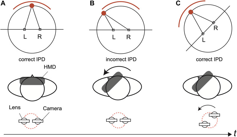
FIGURE 6. IPD change in the TeleParallax system. The cameras provide a stereo image with the correct IPD (A). When head motion occurs, the viewer sees another stereo image without blurring thanks to the panoramas, but the IPD is incorrect (B). The stereo image is slowly updated to one with the correct IPD (C). Note that the midpoint between the observer’s eyes lies off the axis of rotation.
2.2 Evaluation
2.2.1 Image Stability
We compared the motion blur of the images during head motion tracking generated by our system with the blur generated by a system that simulates a common stereo camera. A Siemens star test pattern (Figure 7A) with a diameter of 200 mm printed on a sheet of paper was placed in front of the viewer (0°) at a distance of 573 mm from the camera lens. The cameras were then rotated in the yaw direction (−15 to 15° or −30 to 30°), as shown in Figures 7F,G. The duration of the rotation was 700 ms, that is, the mean rotational velocity was 42.8 or 85.7 deg/s.
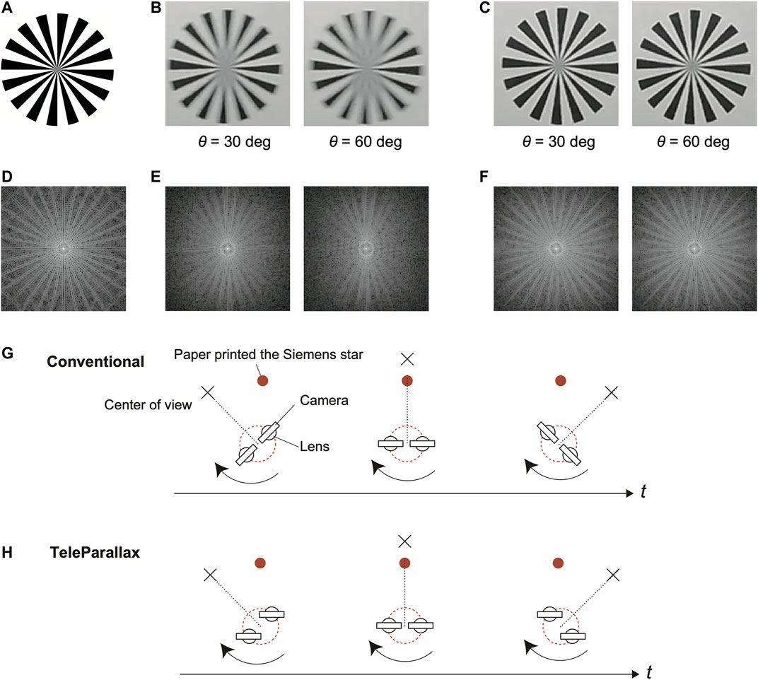
FIGURE 7. Original image of the Siemens star (A). Images captured during head motion with the conventional two side-by-side omnidirectional cameras (B) and our proposed system (C). Here, θ is the amplitude of the yaw rotation. Power spectra of the original image (D), the captured image for the conventional setup (E), and that for our proposed system (F). Measurement of the rotation of the cameras to capture an image of the Siemens star test pattern for a conventional stereo camera setup (G) and (H). The total amount of rotation θ was 30 or 60°.
The result for the conventional stereo camera setup reveals that the center of the captured Siemens star was unclear, as shown in Figure 7B. In contrast, the result for our proposed system was not blurred, as shown in Figure 7C. Figures 7D–F show the power spectra of the original Siemens star image, an image captured by the conventional setup, and that captured by the TeleParallax system. The high-frequency range of the conventional setup (Figure 7E) in the x-direction was narrower than that of the TeleParallax system (Figure 7F) owing to the motion blur in the x-direction. These results confirm that the motion blur in the image displayed on the HMD is reduced by TeleParallax.
2.2.2 Baseline Stability
We measured the change in the baseline, that is, the distance between the camera lenses of TeleParallax, when the viewer wears an HMD and performs head rotations. The baseline was set to 64 mm. The movement of an HMD was measured by an inside out camera-based tracking system embedded in the HMD. Next, the posture data were sent to the computers to control the robot arms. We attached passive reflective markers to the HMD and two omnidirectional cameras and defined them as rigid bodies using a motion capture system (Optitrack Trio; 120 Hz of sampling frequency). We then measured their position and orientation. In the test environment, the posture data of the HMD were transmitted directly to the robotic arms by specifying the IP address instead of using a WebRTC connection. All the posture data obtained by the motion capture system were processed by a low-pass filter (with a cutoff frequency of 10 Hz). In this experiment, we asked the viewer to perform a series of head movements, including yaw rotation (from 30 to 35 s after the start of the experiment) and roll rotation (from 40 to 45 s after the start of the experiment) as the viewer looked around. Figure 8 shows the measurement results.
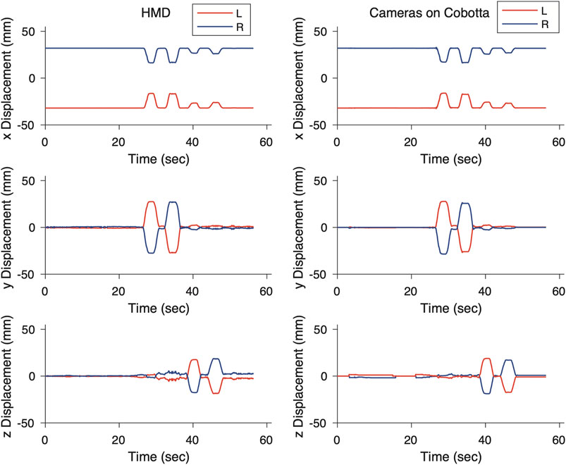
FIGURE 8. Position profiles of eyes and camera lens during head motion.
Figure 9A shows the distance between the two lenses. The maximum error for roll rotation was approximately ±0.4 mm, whereas the maximum error for yaw rotation was approximately ±1.7 mm. This is because the cameras were not affixed to the end of the robotic arms but to an extension link connected to the end of the robotic arms. Because we performed position control using the end of the robot arms as a target, the angular error was magnified by the extension link.
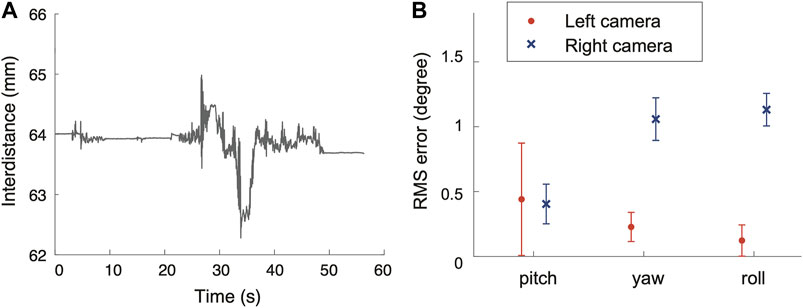
FIGURE 9. Change in interlens distance (A). RMS error of the direction of the lens (B).
The root mean squared (RMS) error with respect the initial value of the camera lens orientation at this time is shown in Figure 9B. The results show that the orientation of the camera lens can be controlled in the world coordinate system with an error of less than 1.3°, even during head movements.
A cross-correlation was calculated to establish the time lag between the head motion of the HMD and the robot arm motion. The result showed that the system lag was 0.042 s. A communication delay of 0.2–0.5 s is added when WebRTC is used.
3 Experiment
We conducted three user studies: 1) to determine the effect of the IPD change due to the roll tilt of the viewer’s head on depth perception while observing stereoscopic scenes, 2) to confirm a perceivable delay between the eyes, and 3) to investigate the detection of a change from incorrect to correct IPD during yaw rotation of the viewer’s head.
3.1 Participants
Sixteen participants took part in a series of experiments (age range 18–34, 8 females; the average IPD was 64 ± 3 mm). All participants reported having normal or corrected-to-normal vision and reported that they did not have deficits in stereovision. This was ensured by testing their depth perception using the Random Dot E stereotest and asking them to distinguish between a “raised E″ and a non-stereo target through viewing glasses. All the participants passed this test.
The study was conducted in accordance with the Declaration of Helsinki and the ethics committee of the University of Tokyo (approval number: UT-IST-RE-191108–1). All participants provided written informed consent and were naïve about the aim of the study.
3.2 Apparatus and Stimuli
The participants were presented with stereoscopic stimuli using two omnidirectional cameras through immersive virtual reality using an HMD (Vive Cosmos, HTC Inc.; refresh rate 90 Hz, 1,080 × 1,200 pixels for each eye). Unity (2018.2.7f1, Unity Technologies) was used to present the visual scenes to each eye. All the images used in the experiments were taken using two omnidirectional cameras (Ricoh THETA Z1) on the TeleParallax system.
3.3 General Procedure
The participants were seated while wearing the HMD. They were then instructed to fixate on a red cross at the center of the view. Subsequently, stereoscopic visual stimuli were presented during two different time intervals in Experiments 1 and 3 (i.e., the two-interval forced choice paradigm or 2IFC) and during one interval in Experiments 2 (i.e., the yes–no paradigm). The order of stimuli in the blocks was randomized for each participant. In the response phase, the participants completed questionnaires presented using the HMD and a numeric keypad. The participants were told that they did not have to respond quickly, and they were given no feedback. The experiment was initiated with a training session (10 trials), followed by the four blocks of the experiment separated into two blocks each.
To eliminate the influence of fatigue, participants had at least a 5-min break after every block, but could rest at any time. The total time of the three experiments for a typical participant was approximately 2 h.
3.3.1 Experiment 1: Depth Perception With Head Roll Tilt
Two static stereoscopic photos were presented in temporal order on the HMD. The participants were asked to choose which of the two photos provided a greater sense of depth using a 2IFC judgment task. In addition, the participants reported which of the two intervals contained the stimulus that caused more visual discomfort. The duration of the intervals was 5 s.
The following four visual stimuli were evaluated: 1) Stereoscopic 0°: the photos for each eye were taken with the correct IPD; 2) Stereoscopic 30°: the photos for each eye were taken with an IPD that is correct when the head is tilted at 30° toward the left shoulder; 3) Monoscopic: the photos for each eye were identical; and 4) Left-right swapped: the photos for each eye were swapped. The distance between the lenses of the cameras was 64 mm, and the angle between the interlens axis and the horizontal axis was either 0° (stimuli 1, 3, and 4) or 30° (stimulus 2). Two scenes were selected for the photos: inside a building (objects located nearby) or outside (objects located far away), as shown in Figure 10. In each trial, one pair of visual stimuli was randomly chosen for the scenes.
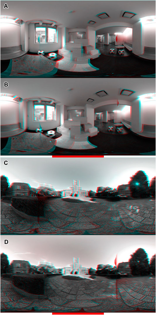
FIGURE 10. Visual stimuli for experiment 1. Still stereo photos in equirectangular format captured by the same TeleParallax configuration when tilting the head 0° (A,C) or 30° (B,D) in the roll direction, converted into gray anaglyphic stereo. The red horizontal bar on the bottom indicates the field of view of the HMD (120°). The red (or blue) vertical stripes which appeared out of the field of view were the omnidirectional camera taken by the other camera.
In one half of the experiment, the head of the participant was tilted 30° toward the left shoulder (i.e., the right eye was higher than the left eye) using a chin rest. In the other half, the head was upright to keep the viewer’s interocular axis horizontal (0°).
The participants experienced 2 viewer head tilt (upright or 30° head tilt) × 2 scene (indoor or outdoor) × 4 visual stimuli × 2 repetitions. To minimize time-dependent effects, we reversed the order of the viewer head tilt conditions using an ABBA design.
3.3.2 Experiment 2: Synchronous Detection for Each Eye
In the prototype, the omnidirectional cameras used for each eye did not have a synchronization signal. In general, the images from the cameras were captured and sent at almost the same time but synchronization was not guaranteed. Thus, Experiment 2 clarifies the perceptual threshold of synchronous detection.
The stereoscopic videos were presented on the HMD. The task of the participants was to choose which scene of the video appeared to be more synchronous between the displays on each eye. We created stimulus videos by artificially adding a temporal gap between the movies presented to the left and right eyes of the HMD, which were created using video editing software (Adobe Premier Pro 2020; Adobe Inc.) and presented by Unity (2019.2.10f1, Unity Technologies). The delay between the displays on each eye ranged from 0 to 70 ms in steps of 10 ms. The scene of the stimulus videos included two metronomes swinging at frequencies of 0.67 and 1.5 Hz. In addition, the participants were asked which of the two videos had greater depth. The participants experienced 8 delay times × 14 repetitions. All the stimulus videos were 5 s in length.
3.3.3 Experiment 3: Detection of Interpupillary Distance Change
In the prototype, the omnidirectional cameras move from an incorrect to the correct IPD during yaw rotation of the viewer’s head. Ideally, the velocity of the cameras’ motion should be set to be small enough not to be noticed by the viewer. Thus, Experiment 3 clarifies the perceptual threshold of motion detection during the IPD modification.
The stereoscopic videos were presented on the HMD. The participants were asked to choose which scene of the video appeared to be moving. The scene of the stimulus videos was an indoor scene moving in the yaw direction from −30 to 0°, as shown in Figure 11. The mean velocity of the camera motion from the initial position to the final position was 15, 30, 50, and 75°/s. The control condition was no motion, that is, static photos of the final view. In addition, the participants were asked to choose which of the two videos gave a greater sense of depth using a 2IFC judgment task. The participants experienced 5 velocities × 7 repetitions. Each of the stimulus videos had a duration of 3 s.
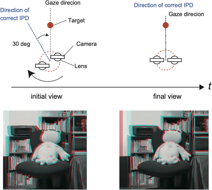
FIGURE 11. Stereoscopic visual stimuli for experiment 3. In the initial view, the direction of the gaze to the target and the direction of correct binocular disparity were not aligned. After a rotation in the yaw direction, the two directions were aligned so that the observer could see the scene with the correct IPD. The rotational velocity was varied as 15, 30, 50, and 75°/s. The bottom images show screenshots in the gaze direction of the initial and final views converted into gray anaglyphic stereo.
3.4 Result
3.4.1 Experiment 1
In the first experiment, we used the method of paired comparison to determine which gives a stronger depth perception and more visual discomfort: a head tilt of 0° (upright) or 30° to the left. We converted the data of the paired comparison into a Thurstone scale (Thurstone, 1927) and used a two-tailed binomial test to evaluate the significance of the proportions of the paired comparison with respect to a chance level of 50%. In Figure 12, a single asterisk indicates significance at p < 0.05, a double asterisk indicates p < 0.01, and a cross indicates p < 0.10.
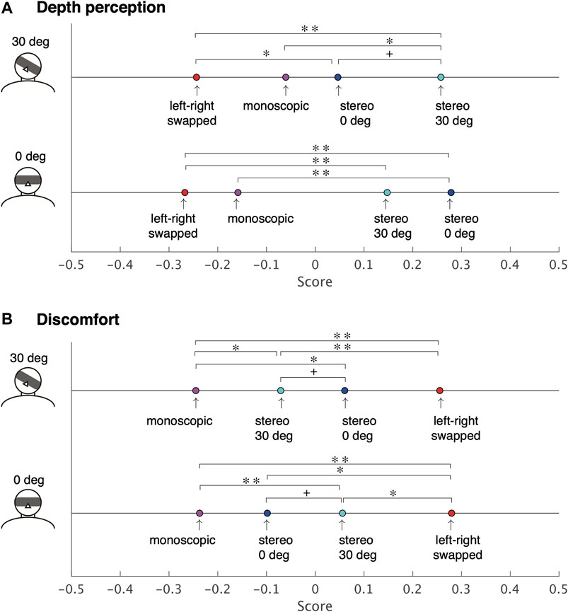
FIGURE 12. Thurstone scale of the depth perception (A) and the visual discomfort (B) when the observers tilt their head in the roll direction (Experiment 1). (**p < 0.01, *p < 0.05, +p < 0.10).
For depth perception, the results show that the participants felt that stereoscopic 0° was the best under the condition of a head tilt of 0°, whereas stereoscopic 30° was the best under a head tilt of 30° (Figure 12A). The monoscopic and left-right swapped stimuli provided less sensation of depth than the best one under either head-tilt condition (p < 0.05).
For visual discomfort, the results show that the monoscopic produced the least discomfort, whereas the inverted condition produced the most discomfort under either head-tilt condition (Figure 12B). Stereoscopic 0° caused less discomfort than stereoscopic 30° when the head tilt was 0° (p < 0.10); conversely, stereoscopic 30° led to less discomfort than stereoscopic 0° when the head tilt was 30° (p < 0.10).
3.4.2 Experiment 2
In the second experiment, we used the yes–no task method to judge whether the participant felt a sensation of depth and whether they saw a double image of the visual stimuli.
For depth perception, the proportion of “I felt depth perception” responses did not differ with respect to delay (Figure 13A). We ran a Friedman test on the response, and the comparison did not show any significant differences under different delays (χ2 (7) = 6.29, p = 0.51).
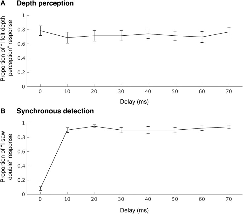
FIGURE 13. Mean ratio of depth perception (A) and synchronous detection (B) in experiment two.
The proportion of “I saw double” responses did not differ across the delays except at a delay of 0 ms (Figure 13B). Friedman’s test was performed on the responses and showed a significant difference (χ2 (7) = 71.63, p < 0.001). A post hoc test with Bonferroni correction exhibited significant differences with respect to a delay of 0 ms and the other delays.
3.4.3 Experiment 3
In the third experiment, we used the method of paired comparison to judge which interval led to a greater depth sensation and a greater motion. For depth perception, the proportion of “I felt a greater sensation of depth from the test stimulus than from the control stimulus” responses exceeded 50% (change level) for all camera velocities (Figure 14A). We used a two-tailed binomial test to evaluate the significance of these proportions with respect to the chance level. The results show that the proportions were significantly higher than the chance level for all velocities (ps < 0.001). In addition, Friedman’s test was performed on the responses and did not show any significant differences among velocities (χ2 (3) = 0.87, p = 0.83).
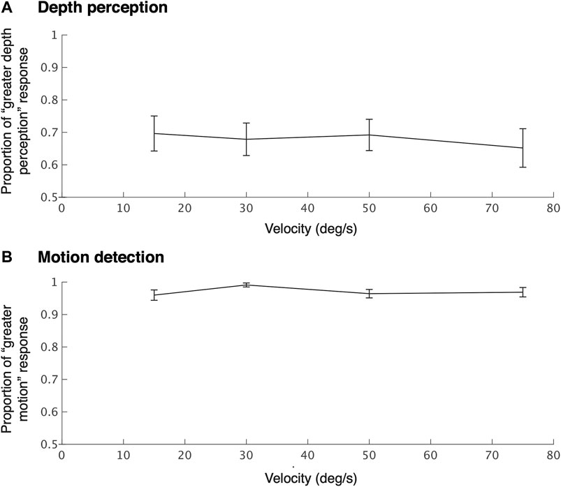
FIGURE 14. Mean ratio of higher depth perception (A) and more motion detection (B) than the control condition (still image) during yaw rotation to update a stereo image with the correct IPD in experiment 3.
Figure 14B shows the proportion of participants who stated “I felt a greater motion in the test stimulus than the control stimulus motion” with respect to the velocity of cameras. We used a two-tailed binomial test to evaluate the proportion with respect to the chance level of 50%. The proportions were significantly higher (>95%) than the chance level for all velocities (ps < 0.001). Furthermore, performance did not significantly change across velocities (Friedman test: χ2 (3) = 5.06, p = 0.17).
4 Discussion
4.1 Summary of Results
We proposed the HMD-based telepresence system TeleParallax, which aims to keep the IPD consistency and vertical disparity by employing two six-DoF robot arms. Two omnidirectional cameras synchronously move with the head posture without changing the orientation of the cameras to reduce the image blur caused by head motion and provide accurate binocular disparity for 3D head rotation. We confirmed that the images obtained by TeleParallax are not blurred or are less blurred during head motion tracking than those by a common stereo camera configuration. We confirmed that the distance between the camera lenses in TeleParallax was unchanged during 3D rotations of the head. Based on the proposed configuration, three experiments with sixteen participants were conducted. Experiment 1, examining depth perception and visual discomfort when head tilting in the roll direction, showed that the observers felt a sense of depth mostly when matching their IPD and the inter-lens distance. Experiment 2, examining binocular fusion delay, showed that the observers were sensitive to the asynchrony between images for each eye, even with 10 ms delay. Experiment 3, which examined the ability of users to detect motion when a stereo image with incorrect binocular disparity was updated to have the correct binocular disparity, showed that the observers were sensitive to the motion even at a rotation of 15°/s. However, experiments 2 and 3 showed that the observers felt a depth perception within interocular delays of 70 ms and a motion velocity of 75°/s. Thus, these results suggest that the proposed system can be applied to practical telepresence scenarios while guaranteeing the sense of depth.
4.2 Depth Perception With Head Tilt
Tilting the head toward one shoulder or the other decreases the horizontal separation between the eyes, thereby decreasing the IPD (Lam et al., 2008). When the head is tilted 30° in the roll direction, the orthogonal projection of the IPD to the horizontal plane is equivalent to approximately 55 mm. Therefore, when using an HMD in which the IPD is fixed at 64 mm, the viewer feels as if his or her body has become smaller or does not see stereoscopic images accurately. In the TeleParallax system, these problems are solved by moving the camera lens on a spherical surface instead of a circumference in the plane. Our user studies revealed that the stereoscopic image that matches the participant’s head tilt was rated highest for depth perception. The first user study demonstrated that the stereoscopic images captured with a tilt at 30° (0°) led to a strong perception of depth when the head was tilted at 30° (0°) toward the left shoulder. It has been reported that depth perception remains intact with a relatively small rotation of the head of up to 12°, regardless of the rotation direction and viewing distance, which is due to a tolerance mechanism for stereoscopic processing in the human neural system (Darmohray et al., 2009). Therefore, our TeleParallax will be beneficial with a head tilt of more than 12° as shown in the first experiment.
4.3 Visual Discomfort With Head Tilt
Visual discomfort can be caused by many factors when viewing stereo displays, such as ghosting or crosstalk between the two images, misalignment of the images, inappropriate head orientation, vergence-accommodation conflict, and visual-vestibular conflicts (Kooi and Toet, 2004). It is often reported that stereoscopic displays generate visual discomfort because of 3D artifacts resulting from insufficient depth information (Lambooij et al., 2009). Our result in the first experiment showed a clear correlation between depth perception and visual discomfort for the three stereoscopic conditions.
In contrast, our result also showed that the visual discomfort of the stereoscopic conditions was not less than that of the monoscopic condition. This may be due to individual differences in the IPD of the participants. Although the average IPD of the participants was almost identical to the camera’s baseline, a few participants reported that some stereoscopic images seemed to fuse poorly and it felt like they were out of focus. In the user study, we did not adjust the camera’s baseline for each IPD to normalize the visual stimulus for all participants. Stanney et al. (2020) reported that poor IPD fit was the primary driver of gender differences in cybersickness, and visual discomfort is a subcategory of cybersickness. Future study will include baseline adjustment for individual IPDs because TeleParallax is able to change the camera’s baseline.
In addition, the omnidirectional videos using fisheye lenses must introduce distortion by nature. In fish-eye images, features distortions increase nonlinearly from the center to the sides of the images. We did not conduct distortion correction except one provided by the image processor in the camera. This might affect depth perception and user comfort.
4.4 Asynchrony for Each Eye
When we used WebRTC to transmit the video and posture data, we found that there was a perceptible delay. When the cameras rotate quickly, the images are presented to both eyes without blurring, owing to the omnidirectional camera in the TeleParallax system. The binocular disparity of the images is incorrect at first, but it slowly changes to images with the correct binocular disparity. Therefore, the viewer spends more time viewing unnatural 3D images because of the long delay. The results of the second user study indicate that delays of 10 ms can be detected by most participants, which is the minimum frame time of the HMD used in the experiment (i.e., the HMD has a refresh rate of 90 Hz). We cannot determine the threshold for the synchrony between eyes because this refresh rate means that one frame is displayed for about 11 ms.
In addition, the task difficulty of delay detection depends on the temporal resolution of the contents of the stimulus video. Our stimulus video included quick motion generated by the two metronomes, which enabled the difference between each eye be detected easily. However, the participants felt a sensation of depth at delays of less than 70 ms. This indicates that the participants were able to perceive sufficient depth perception even with the stimulus video.
4.5 Detection of Interpupillary Distance Modification
The stereo image obtained by TeleParallax was slowly updated to the one with the correct binocular disparity by matching the positions of the two cameras with those of the viewer’s eyes as shown in Figure 11. Our third user study confirmed that the motion of the view can be detected when the cameras are rotated to provide the correct IPD. The participants reported that they detected a motion of only a few pixels over a rotation of 30°. In the experiment, the participants did not move their heads voluntarily. If they moved their heads, the relative motion would be contaminated with the participant’s head and camera motions. This may explain why they could detect a motion from a subtle deviation.
However, depth perception when the cameras were moving to modify IPD was greater than that when not moving. This enhancement of the depth perception appears to be due to a relative image motion by the camera motion, which is similar to that which occurs when the viewer’s head moves.
Some recent studies indicate that what strains the ocular system may be the temporal modification of horizontal disparities more than their presence (Cai et al., 2017), that is, visual fatigue is mainly caused by generating, but not sustaining, stereovision. TeleParallax can sustain stereovision by keeping the correct IPD for 3D head rotation. Therefore, it would be beneficial for viewers to use TeleParallax configuration to avoid visual fatigue.
4.6 Design
One may argue that a system with only one robotic arm, two wide-angle cameras horizontally separated by a fixed baseline, and adequately programmed 3D motion can provide the same function as the TeleParallax. However, an additional mechanism would be required to control the 3D positions and orientation of the two cameras because they cannot be controlled by only one robotic arm. In the prototype, we used two robotic arms as a control to keep the baseline fixed and the orientation of the cameras remain unchanged when following three-dimensional head rotations. To reduce the number of the robotic arms, a rotational mechanism such as using stepper motors placed on each camera to keep the orientation unchanged could be used.
4.7 Limitations
Because the TeleParallax system has been designed for a seated viewer, it was not designed for continuous head rotation or for tilting the head at 90°. If the yaw rotation of the head exceeds ±160° or the pitch rotation exceeds ±45°, it will be necessary to consider software to switch the correspondence between the left and right displays and each camera.
The viewpoint of TeleParallax can move within a limited range because of the robotic arm. Thus, motion such as approaching or moving away from an object is reflected in the observer’s view. However, TeleParallax was unable to move around freely in this study. To enable it to do so, the TeleParallax system could be mounted on a vehicle such as a personal transporter (Segway (Yem et al., 2019)), a quadrupedal robot (SpotMini (Boston Dynamics, Inc.)), or an unmanned aerial vehicle (Higuchi and Rekimoto, 2013).
As shown in Figure 5, the omnidirectional cameras capture the robot arms in the bottom of the scene. Note that they are usually out of the field of view (see Figure 10A). However, if the viewers looked down, they would see the robot arms, which were connected to the omnidirectional cameras. This might affect the subjects’ depth perception. For future studies, we shall examine this effect by asking participants to keep their eyes lowered.
We did not use standard questionnaires to measure simulator sickness (Kennedy et al., 1993), although it is a crucial issue in telepresence systems. Because the duration of visual stimuli was shorter than 10 s in all experiments, no participants reported severe simulator sickness. We will use questionnaires to measure motion sickness in our TeleParallax system in future studies.
Delay is unavoidable and randomly time-varying for teleoperation robot systems based on the Internet. In the experiment, we tested TeleParallax in the lowest latency condition between the HMD and the cameras. However, a communication delay in our system is more than 0.2–0.5 s with the WebRTC connection. It has been reported by the time delay problem in the teleoperation. A recent study in medical robotics reported that more than 0.4 s delay affected the surgeon’s performance (Madder et al., 2020). Therefore, further study is required to confirm that our system works in high-latency networks and approaches to mitigate time delay should be considered (Farajiparvar et al., 2020).
The stereo images for each eye were not synchronized because there was no sync signal input on the cameras used in this study. To obtain the temporal correspondence of the correct stereo images, we could use algorithms that have been proposed for unsynchronized video streams (Zhou and Tao, 2003; Svedman et al., 2005).
5 Conclusion
In this study, we proposed a telepresence viewing system, TeleParallax, to fix the IPD during 3D rotational motion of the remote viewer’s head. In TeleParallax, two omnidirectional cameras are moved by robot arms over a spherical surface whose diameter is the IPD of the viewer. We confirmed that the camera lens orientation can be fixed in the world coordinate system, which reduces motion blur in the image displayed on the HMD. We evaluated the effect of head tilt, interocular delay between eyes, and brief motion of the cameras on depth perception, double-image detection, and the detection of motion. The results show that TeleParallax provides depth perception with less visual discomfort and independent of head movements. In addition, although the results indicate that the users were sensitive to the asynchrony and updating motion of the view, they maintained feeling a depth perception within interocular delays of 70 ms and a motion velocity of 75°/s. These results support the validity of TeleParallax, which provides the correct IPD during head tilt, for visual telepresence system.
This study considered only the factor of consistency of IPD in depth perception cues. Hence, future study will include examining the effect of the communication delay between the viewer side and the camera side on depth perception.
Data Availability Statement
The raw data supporting the conclusions of this article will be made available by the authors, without undue reservation.
Ethics Statement
The studies involving human participants were reviewed and approved by the ethics committee of the University of Tokyo. The patients/participants provided their written informed consent to participate in this study.
Author Contributions
TA, KA, and MH conceived and designed the experiments. TA collected and analyzed the data. TA contributed to the manuscript preparation. All images, drawings, and photographs were obtained or created by TA. All authors have reviewed the manuscript.
Funding
This research was supported in part by JSPS KAKENHI 21H04883 to TA. This study is supported by Denso Corporation, Japan. The funder was not involved in the study design, collection, analysis, interpretation of data, the writing of this article or the decision to submit it for publication.
Conflict of Interest
The authors declare that the research was conducted in the absence of any commercial or financial relationships that could be construed as a potential conflict of interest.
Publisher’s Note
All claims expressed in this article are solely those of the authors and do not necessarily represent those of their affiliated organizations, or those of the publisher, the editors, and the reviewers. Any product that may be evaluated in this article, or claim that may be made by its manufacturer, is not guaranteed or endorsed by the publisher.
Acknowledgments
The authors would like to thank Tsubasa Morita for his help in developing the first prototype using WebRTC.
Footnotes
1https://www.densorobotics.com/products/software/b-cap/
References
Aggarwal, R., Vohra, A., and Namboodiri, A. M. (2016). “Panoramic Stereo Videos with a Single Camera,” in 2016 IEEE Conference on Computer Vision and Pattern Recognition (CVPR) (IEEE), 3755–3763. doi:10.1109/CVPR.2016.408
Amemiya, T., Aoyama, K., and Hirose, M. (2021). Stereoscopic System Maintaining Constant Optical Axes and Interpupillary Distances for Head Rotations. Tokyo, Japan: Transactions on Virtual Reality Society of Japan, 26.
Anderson, R., Gallup, D., Barron, J. T., Kontkanen, J., Snavely, N., Hernández, C., et al. (2016). Jump: Virtual Reality Video. ACM Trans. Graph. 35, 1. doi:10.1145/2980179.2980257
André-Deshays, C., Revel, M., and Berthoz, A. (1991). Eye-head Coupling in Humans. Exp. Brain Res. 84, 359–366. doi:10.1007/BF00231457
Aykut, T., Lochbrunner, S., Karimi, M., Cizmeci, B., and Steinbach, E. (2017). “A Stereoscopic Vision System with Delay Compensation for 360° Remote Reality,” in Proceedings of the on Thematic Workshops of ACM Multimedia 2017 (New York, NY, USA: Association for Computing Machinery), 201–209. doi:10.1145/3126686.3126751
Baier, H., Buss, M., Freyberger, F., and Schmidt, G. (2003). Interactive Stereo Vision Telepresence for Correct Communication of Spatial Geometry. Adv. Robotics 17, 219–233. doi:10.1163/156855303764018477
Bordas, J. C., Fuchs, P., and Ernadotte, D. (1996). “Stereo Vision and Telepresence,” in Stereoscopic Displays and Virtual Reality Systems III. Editors M. T. Bolas, S. S. Fisher, M. T. Bolas, S. S. Fisher, and J. O. Merritt (San Jose, CA: International Society for Optics and Photonics (SPIE)), 106–114. doi:10.1117/12.237423
Bülthoff, H. H., and Mallot, H. A. (1988). Integration of Depth Modules: Stereo and Shading. J. Opt. Soc. Am. A. 5, 1749–1758. doi:10.1364/josaa.5.001749
Cai, T., Zhu, H., Xu, J., Wu, S., Li, X., and He, S. (2017). Human Cortical Neural Correlates of Visual Fatigue during Binocular Depth Perception: An Fnirs Study. PLOS ONE 12, e0172426–16. doi:10.1371/journal.pone.0172426
Chunxiao Zhou, C., and Hai Tao, H. (2003). “Dynamic Depth Recovery from Unsynchronized Video Streams,” in IEEE Computer Society Conference on Computer Vision and Pattern Recognition (IEEE), 351. doi:10.1109/CVPR.2003.1211490
Cutting, J. E., and Vishton, P. M. (1995). “Perceiving Layout and Knowing Distances,” in Perception of Space and Motion, Handbook of Perception and Cognition. Editors W. Epstein, and S. Rogers (Academic Press), 69–117. doi:10.1016/b978-012240530-3/50005-5
Darmohray, D., Zhou, B., and Poeppel, E. (2009). Tolerance of Stereopsis to Conjunctive Cyclorotation. Perception 38, 1867–1870. doi:10.1068/p6572
Dodgson, N. A. (2004). “Variation and Extrema of Human Interpupillary Distance,” in Stereoscopic Displays and Virtual Reality Systems XI. Editors M. T. Bolas, A. J. Woods, J. O. Merritt, and S. A. Benton (San Jose, CA: International Society for Optics and Photonics (SPIE)), 36–46.
Fang, Y., Nakashima, R., Matsumiya, K., Kuriki, I., and Shioiri, S. (2015). Eye-head Coordination for Visual Cognitive Processing. PLOS ONE 10, e0121035–17. doi:10.1371/journal.pone.0121035
Farajiparvar, P., Ying, H., and Pandya, A. (2020). A Brief Survey of Telerobotic Time Delay Mitigation. Front. Robot. AI 7, 198. doi:10.3389/frobt.2020.578805
Freedman, E. G. (2008). Coordination of the Eyes and Head during Visual Orienting. Exp. Brain Res. 190, 369–387. doi:10.1007/s00221-008-1504-8
Heesy, C. P. (2008). Ecomorphology of Orbit Orientation and the Adaptive Significance of Binocular Vision in Primates and Other Mammals. Brain Behav. Evol. 71, 54–67. doi:10.1159/000108621
Higuchi, K., and Rekimoto, J. (2013). “Flying Head,” in CHI ’13 Extended Abstracts on Human Factors in Computing Systems (New York: Association for Computing Machinery), 2029–2038. doi:10.1145/2468356.2468721
Ikei, Y., Yem, V., Tashiro, K., Fujie, T., Amemiya, T., and Kitazaki, M. (2019). “Live Stereoscopic 3D Image with Constant Capture Direction of 360° Cameras for High-Quality Visual Telepresence,” in IEEE Conference on Virtual Reality and 3D User Interfaces (IEEE), 431–439.
Johnston, E. B., Cumming, B. G., and Parker, A. J. (1993). Integration of Depth Modules: Stereopsis and Texture. Vis. Res. 33, 813–826. doi:10.1016/0042-6989(93)90200-g
Kane, D., Held, R. T., and Banks, M. S. (2012). “Visual Discomfort with Stereo 3D Displays when the Head Is Not Upright,” in Stereoscopic Displays and Applications XXIII. Editors A. J. Woods, N. S. Holliman, and G. E. Favalora (San Jose, CA: International Society for Optics and Photonics (SPIE)), 384–393. doi:10.1117/12.912204
Kennedy, R. S., Lane, N. E., Berbaum, K. S., and Lilienthal, M. G. (1993). Simulator Sickness Questionnaire: An Enhanced Method for Quantifying Simulator Sickness. Int. J. Aviation Psychol. 3, 203–220. doi:10.1207/s15327108ijap0303_3
Kooi, F. L., and Toet, A. (2004). Visual comfort of Binocular and 3d Displays. Displays 25, 99–108. doi:10.1016/j.displa.2004.07.004
Lam, D. Y., Cheng, T. L., Kirschen, D. G., and Laby, D. M. (2008). Effects of Head Tilt on Stereopsis. Binocul. Vis. Strabismus Q. 23, 95–104.
Lambooij, M., Fortuin, M., Heynderickx, I., and IJsselsteijn, W. (2009). Visual Discomfort and Visual Fatigue of Stereoscopic Displays: A Review. J. Imaging Sci. Tech. 53, 1–14. doi:10.2352/j.imagingsci.technol.2009.53.3.030201
Lanir, J., Stone, R., Cohen, B., and Gurevich, P. (2013). “Ownership and Control of point of View in Remote Assistance,” in Proceedings of the SIGCHI Conference on Human Factors in Computing Systems (New York, NY, USA: Association for Computing Machinery), 2243–2252. doi:10.1145/2470654.2481309
Madder, R. D., VanOosterhout, S., Mulder, A., Bush, J., Martin, S., Rash, A. J., et al. (2020). Network Latency and Long‐distance Robotic Telestenting: Exploring the Potential Impact of Network Delays on Telestenting Performance. Catheter Cardiovasc. Interv. 95, 914–919. doi:10.1002/ccd.28425
Matzen, K., Cohen, M. F., Evans, B., Kopf, J., and Szeliski, R. (2017). Low-cost 360 Stereo Photography and Video Capture. ACM Trans. Graph. 36. doi:10.1145/3072959.3073645
Nityananda, V., and Read, J. C. A. (2017). Stereopsis in Animals: Evolution, Function and Mechanisms. J. Exp. Biol. 220, 2502–2512. doi:10.1242/jeb.143883
Stanney, K., Fidopiastis, C., and Foster, L. (2020). Virtual Reality Is Sexist: But it Does Not Have to Be. Front. Robot. AI 7, 4. doi:10.3389/frobt.2020.00004
Svedman, M., Goncalves, L., Karlsson, N., Munich, M., and Pirjanian, P. (2005). “Structure from Stereo Vision Using Unsynchronized Cameras for Simultaneous Localization and Mapping,” in IEEE/RSJ International Conference on Intelligent Robots and Systems (IEEE), 3069–3074. doi:10.1109/IROS.2005.1545431
Tashiro, K., Fujie, T., Ikei, Y., Amemiya, T., Hirota, K., and Kitazaki, M. (2017). “TwinCam,” in ACM SIGGRAPH 2017 Emerging Technologies (New York, NY: ACM), 24. doi:10.1145/3084822.3084831
Thurstone, L. L. (1927). A Law of Comparative Judgment. Psychol. Rev. 34, 273–286. doi:10.1037/h0070288
van Ee, R., and Erkelens, C. J. (1996). Stability of Binocular Depth Perception with Moving Head and Eyes. Vis. Res. 36, 3827–3842. doi:10.1016/0042-6989(96)00103-4
Vienne, C., Plantier, J., Neveu, P., and Priot, A.-E. (2016). The Role of Vertical Disparity in Distance and Depth Perception as Revealed by Different Stereo-Camera Configurations. i-Perception 7, 204166951668130. doi:10.1177/2041669516681308
Vishwanath, D. (2014). Toward a New Theory of Stereopsis. Psychol. Rev. 121, 151–178. doi:10.1037/a0035233
Votanopoulos, K., Brunicardi, F. C., Thornby, J., and Bellows, C. F. (2008). Impact of Three-Dimensional Vision in Laparoscopic Training. World J. Surg. 32, 110–118. doi:10.1007/s00268-007-9253-6
Watanabe, K., Kawabuchi, I., Kawakami, N., Maeda, T., and Tachi, S. (2008). TORSO: Development of a Telexistence Visual System Using a 6-d.o.F. Robot Head. Adv. Robotics 22, 1053–1073. doi:10.1163/156855308X324767
Wen, M.-C., Yang, C.-H., Tsai, M.-H., and Kang, S.-C. (2018). Teleyes: A Telepresence System Based on Stereoscopic Vision and Head Motion Tracking. Automation in Construction 89, 199–213. doi:10.1016/j.autcon.2018.01.008
Yanagida, Y., Saito, S., Yano, S., Maeda, T., and Tachi, S. (2001). “A Head-Tracked, Live-Video-Based Telexistence System Using a Fixed Screen,” in Proceedings of ICAT 2001 (Tokyo, Japan: ICAT), 42–47.
Yem, V., Nashiki, R., Morita, T., Miyashita, F., Amemiya, T., and Ikei, Y. (2019). “Twincam Go: Proposal of Vehicle-Ride Sensation Sharing with Stereoscopic 3d Visual Perception and Vibro-Vestibular Feedback for Immersive Remote Collaboration,” in ACM SIGGRAPH Asia 2019 Emerging Technologies (New York, NY: ACM), 53–54. doi:10.1145/3355049.3360540
Keywords: telepresence, binocular, omnidireciontal camera, interpupillary distance (IPD), motion blur
Citation: Amemiya T, Aoyama K and Hirose M (2021) TeleParallax: Low-Motion-Blur Stereoscopic System With Correct Interpupillary Distance for 3D Head Rotations. Front. Virtual Real. 2:726285. doi: 10.3389/frvir.2021.726285
Received: 16 June 2021; Accepted: 23 August 2021;
Published: 06 October 2021.
Edited by:
Dirk Reiners, University of Central Florida, United StatesReviewed by:
Guido Maiello, Faculty of Psychology and Sports Science, Justus Liebig University Giessen, GermanyLuis E. Gurrieri, DFocal Inc., Canada
Michael Langer, McGill University, Canada
Copyright © 2021 Amemiya, Aoyama and Hirose. This is an open-access article distributed under the terms of the Creative Commons Attribution License (CC BY). The use, distribution or reproduction in other forums is permitted, provided the original author(s) and the copyright owner(s) are credited and that the original publication in this journal is cited, in accordance with accepted academic practice. No use, distribution or reproduction is permitted which does not comply with these terms.
*Correspondence: Tomohiro Amemiya, YW1lbWl5YUB2ci51LXRva3lvLmFjLmpw