 Pouria Razzaghi
 Milad Memarzadeh2
 Krishna Kalyanam
- 1Metis Technology Solutions, Inc., NASA Ames Research Center, Moffett Field, CA, United States
- 2Aviation Systems Division, NASA Ames Research Center, Moffett Field, CA, United States
This study explores the use of formal verification techniques to evaluate the efficacy of suggestions made by the Runway Configuration Assistance (RCA) tool, a machine learning-based decision support system that our group developed independently. By using model-checking approaches, in particular Computation Tree Logic (CTL), this study verifies the compliance of the RCA tool with predefined safety regulations under different conditions of surface winds. By simulating a range of scenarios at three major US airports, Charlotte Douglas International Airport (CLT), Denver International Airport (DEN), and Dallas-Fort Worth International Airport (DFW), we thoroughly test the predictions of the tool to ensure that they meet strict safety margins with respect to crosswind and tailwind. The application of formal verification methods provides a strict analysis of the RCA tool, enhancing its validity and utility for possible implementation in an operational environment. Initially, a Monte Carlo simulation is carried out to analyze all possible wind conditions both velocity-wise and direction-wise. This part is intended to rigorously test the model against extreme, worst-case conditions to evaluate its performance. Second, we improve our methodology by performing simulations driven by realistic scenarios informed by actual historical data. This approach allows for a more accurate reflection of typical wind conditions (seen in the test airport) and provides a robust assessment of the model’s effectiveness in maintaining safety standards under realistic environmental conditions. The model-checking reveals that overall
1 Introduction
Runway Configuration Management (RCM) is the task of selecting appropriate runways for arriving and departing aircraft at an airport. It is a complex task that involves multiple stakeholders and must take into consideration air traffic services (ATS), weather, and other contributing factors at an airport. Typically, it involves either switching the runway direction for takeoff and landing or switching between different (combinations of) runways available on the airport surface. Most airports, depending on the surface geometry, capacity, and local weather patterns, have multiple configurations that can be used. Many factors, including incoming/outgoing traffic load, wind direction and speed, convective weather, cloud ceiling, and other environmental or noise-related factors, can affect the choice of runway configuration. In current practice, air traffic controllers (ATC) select the runway configuration based on information (weather, traffic, and other forecast) available to them at the time of decision making. As a general rule, it is preferred that the aircraft take off and land into the wind (for maximal lift and braking, respectively). So, the surface wind (speed and direction) is the dominant feature that determines the runway configuration. However, the human decision making process is subjective based on training and expertise, which can be impacted by bias and can sometimes lead to poor outcomes. In particular, for airports with multiple available configurations, dynamic traffic and weather patterns can make it difficult for humans to compute optimal solutions in near real time (Memarzadeh et al., 2023).
In recent years, automated approaches based on Artificial Intelligence (AI) and Machine Learning (ML) have been proposed to solve the RCM problem (Razzaghi et al., 2024). A popular approach used in this context is online Reinforcement Learning (RL) and variants such as discrete choice modeling (Avery and Balakrishnan, 2016), dynamic programming (Li et al., 2009), and queueing theory (Jacquillat et al., 2017; Badrinath et al., 2019) have been proposed. The goal is to model the dynamics of surface operations at an airport and use a simulator to learn a near-optimal policy for the runway configuration selection problem. However, building an accurate simulator (and/or learning accurate models for the surface dynamics) is hard. On the other hand, model-free RL approaches such as Monte Carlo Tree Search (MCTS) (Browne et al., 2012) can be used to learn a near-optimal policy by interacting directly in the operational environment. However, this interaction is not possible in safety-critical environments, since the model tends to make mistakes at the early stages of learning, which we cannot afford to do. So, in the absence of a good model (simulator) and difficulties in learning in the real-world environment, we turn our attention to offline model-free RL.
To go into the evaluation of our approach, this paragraph introduces the verification method applied to the RL model. Model-checking is a formal verification method used to assess whether a system’s finite-state model satisfies specified requirements. The underlying verification mechanism is based on the popular model-checking technique called temporal logic (Bérard et al., 2013). Specifications, typically articulated through temporal logic, that is, Linear Temporal Logic (Vardi, 1996) or Signal Temporal Logic (Baheri et al., 2022), or Computation Tree Logic (CTLogic) (Li et al., 2015), define properties over time, including safety properties. The algorithm then systematically explores the state space of the model to check if the specification is valid. Upon detecting a specification breach, a counterexample showcasing the fault is provided. Although model-checking streamlines the verification process through automation and ensures thorough system examination, it faces the challenge of managing the rapidly expanding state space associated with complex systems. Also, a recent trend in formal verification of AI systems is including hybrid system verification and runtime monitoring (AlSobeh, 2024; Paul et al., 2023), which makes this more challenging. Despite these challenges, our study employs the CTLogic process to validate the RCM model, which does not have a large and complex state space and can be deployed in an offline manner.
In previous work, we adopted an offline model-free RL methodology, known as Conservative Q-Learning (CQL) (Kumar et al., 2020), to successfully tackle the RCM problem (Memarzadeh et al., 2023; Nethi et al., 2024). The tool we developed to provide runway recommendations is referred to as the Runway Configuration Assistance (RCA) tool - for details, see (Memarzadeh et al., 2023; Nethi et al., 2024). The offline nature of the tool removes the need for interactions with the operational environment. Instead, the RCA tool relies only on historical data which includes all relevant system state, input (human decisions), and output (traffic flow) to identify a near-optimal policy.
Given the safety critical nature of the problem, it is crucial that a thorough verification and validation of the RCA tool is performed. As a first step in this direction, we investigate a verification process to ensure that the outcomes of the RCA tool adhere to predefined safety criteria. It is important to note that the safety criteria discussed here relate only to the wind conditions under which runway operations are regarded safe. The verification method used ensures that the recommendations made by the RCA tool comply with these conditions. Ultimately, airport controllers guarantee the overall safety of the system by applying their expertise to ensure that all operational guidelines and safety standards are rigorously upheld.
In the first part of the verification process, we randomly sample wind conditions (both speed and direction) and pipe them into the RL model (RCA tool) and assess whether the output, i.e., recommended runway configuration, meets the safety standards. Specifically, we are performing an experiment as follows: for the selected wind speed and direction and the recommended runway configuration (RCA tool output), is it safe for aircraft to takeoff and land as stipulated by the tailwind and crosswind safety criteria? We then record the response to this question to compute the validation performance metrics. In the second part, the verification process will be repeated by more realistic scenarios coming from real data. The process will identify the boundaries within the input ranges where the system remains safe. The approach will be performed using data from three major US airports, Charlotte Douglas International Airport (CLT), Denver International Airport (DEN), and Dallas-Fort Worth International Airport (DFW).
2 Model-checking
Model-checking, a formal and automated verification method, is widely used in various fields, including computer software, hardware systems, communication protocols, control systems, and security authentication protocols (Baier and Katoen, 2008). When verifying complex concurrent systems, it is typical to come across uncertain and inconsistent information. For example, intelligent autonomous transport systems often generate complex computing tasks for autonomous vehicles (Gao et al., 2022). Model-checking is a technique to verify whether a given system model satisfies a specified property, typically expressed in temporal logic such as CTLogic, which is branching-time logic. This means that it allows one to express properties over trees of possible execution paths (states) rather than linear paths.
2.1 System model
First, let us define the system model as a tuple
2.2 CTLogic syntax
The CTLogic formulas are built from
2.3 Basic model-checking algorithm
This section includes previously developed material, reintroduced here to enhance clarity and ensure completeness of the discussion. A high-level approach to the CTLogic model-checking algorithm is provided below:
1. Labeling states with
2. Recursive Check: For each subformula
□ EX
□ AX
□ EF, EG, AF, AG: Use fixpoint computations. For instance: □ EF
3. Evaluate the main formula: The root of the CTLogic formula (or the main property to check) is evaluated last, utilizing the results from the evaluations of its subformulas.
4. Interpret results: The algorithm returns whether the initial state (or any specified state) of the model satisfies the CTLogic formula.
2.4 Model-checking algorithm for an ML system
Using model-checking to verify properties of an ML model involves a fairly abstract and theoretical approach, as CTLogic is traditionally used to check logical properties in systems described by state-transition models. However, we can conceptualize how this might be approached by considering the ML model as a dynamic system where each state represents a set of parameters or decisions, and transitions reflect changes or iterations in the learning process, or the final outcomes of the model.
2.4.1 Steps to conceptualize CTLogic model-checking for ML models
1. Define the System Model:
2. Specify Properties in CTLogic: You would need to define the properties you want to verify in CTLogic. For an ML model, these might involve convergence, stability over epochs, or fairness metrics, depending on the interpretability of the ML model’s operations as logical transitions.
3. Labeling States: Each state must be labeled with APs that are true in that state. For an ML model, these labels could be derived from the performance metrics, error rates, or other measurable output of the model at each point.
4. Build the Transition System: Construct a transition system where each node corresponds to a state of the ML model at a given point, and directed edges represent transitions due to steps.
5. Run CTLogic model-checking: Using a model-checking tool or library that supports CTLogic (e.g., NuSMV, SPIN), run the model-checking process on the constructed transition system with the CTLogic properties defined in Step 2.
6. Interpret Results: Analyze the results from the model checker to understand whether the ML model satisfies the specified properties.
We should note that the formal model-checking is conducted after training to verify the safety constraint satisfaction of the RCA tool for both synthetic and real wind condition scenarios. Training in offline reinforcement learning is separate from verification. The RCA tool is first trained using historical data via CQL. Then, the verification module uses CTLogic-based model-checking to check if the output of the trained model satisfies operational safety constraints for a range of wind conditions.
2.5 Model-checking algorithm on RCA tool
In this section, we will present the model-checking algorithm for the RCA tool and check the basic CTLogic formulas, i.e., (EF, EG)
We should note that here model-checking was performed using the NuSMV tool due to its support for CTL logic. Simulations and policy inference are executed using Python 3.9 and NumPy/Pandas for data manipulation. Historical wind transitions are modeled using custom-built probabilistic transition matrices derived from datasets.
2.5.1 Safety criteria
The criteria that ensure safe runway selection are based on crosswind and tailwind limits. These limits are determined according to the active runway and state that wind components must not exceed specified thresholds. These thresholds are typically derived from aircraft performance manuals or operational regulations, which stipulate the maximum allowable values for crosswind and tailwind. For instance, for a Boeing 737–300 on a dry runway, the maximum permitted crosswind and tailwind speeds are 29 and 10 knots, respectively. If the surface wind speed exceeds these limits during takeoff or landing, the structural safety of the aircraft could be compromised. Both the Federal Aviation Administration (FAA) and the International Civil Aviation Organization (ICAO) recommend these maximum limits of the wind component to ensure safe flight operations. According to FAA Order 8400.9 (FAA, 1981), the safety standards are as follows:
1. Dry Runway: 25 kts
2. Wet Runway: 15 kts
3. Contaminated Runway: 15 kts
1. Dry Runway: 10 kts
2. Wet Runway: 10 kts
3. Contaminated Runway (
4. Contaminated Runway (
A contaminated runway is one that has standing water, ice, snow, slush, or any material that will reduce braking ability. The FAA defines certain values of the wind component for contaminated surfaces due to increased risk during takeoff and landing. Before establishing the crosswind and tailwind criteria, it is essential to define the coordinate system used in aviation. This system, as illustrated in Figure 1, is a right-hand Cartesian system where the x-axis points north and the y-axis points east, and the z-axis points down into the earth as the NED (north-east-down) convention.
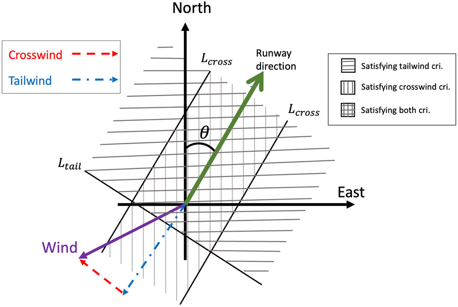
Figure 1. Tailwind and crosswind components and their corresponding criterias in the coordinate system.
In this framework, variables
Let
where,
2.5.2 Definitions of model-checking steps
Building on the concept introduced in Section 2.4.1, we now define wind states (wind speed and direction
All wind conditions that produce identical values for all indicator functions collectively form a wind state, denoted
Transitions, in the context of this research, are changes over time in environmental conditions, namely, wind speed and direction, rather than alterations to the static set of runway configurations. The system transitions through various wind states and, at any given point, the RCA tool determines an appropriate configuration. Verification checks whether these configurations remain compliant with all temporal changes in wind conditions.
By these definitions, we establish a one-to-one mapping transition between runway configuration and wind state. We select two CTLogic properties to verify the safe selection decision made by the RCA tool. These properties are (EF, EG)
To place the use of CTLogic in the context of this research, it is important to redefine the terms “path” and “transition” as they apply to the dynamics of changing runway configurations. Although runway configurations are static by definition (in that each configuration represents a stable operating state), the transitions of interest in this research are defined as changes in environmental conditions, namely, changes in wind speed and direction, over a particular temporal frame. These wind conditions influence the RCA tool’s decisions at different time steps. Thus, a path in CTLogic corresponds to a trajectory of wind state changes throughout a day or simulation time interval, with the RCA tool making a configuration choice at every time step.
We utilize two temporal logic formulas to check the safety of model outputs:
Accordingly, while a static logic verification might ensure that a particular configuration is safe under given wind conditions, the CTLogic-based model-checking framework utilized here allows us to assess safety temporally—ensuring that the RCA tool always produces safe choices under varying operational conditions. This is a requirement in safety-critical systems, where ongoing compliance over time, not just at a moment, is a basic requirement. Let us consider a smaller example: an airport having two runways, A and B. Suppose that under wind direction
3 Results
The results section is divided into two main parts that examine the verification process in three different airports CLT, DEN, and DFW. The first part of our analysis involves a Monte Carlo simulation, which comprehensively evaluates the tool under all possible wind conditions. In these simulations, we rigorously assess the safety criteria to determine how the model performs under worst-case conditions. In the second part, we refine our approach by conducting simulations based on more realistic scenarios that are informed by actual historical data. This two-pronged strategy allows us not only to test against worst-case wind profiles (which may or may not occur in the real world for the specified airport), but also validate model performance against real-world conditions. All runway configurations and the usage frequency (how often each configuration is used historically) for all three airports are reported in Table 1. Here,
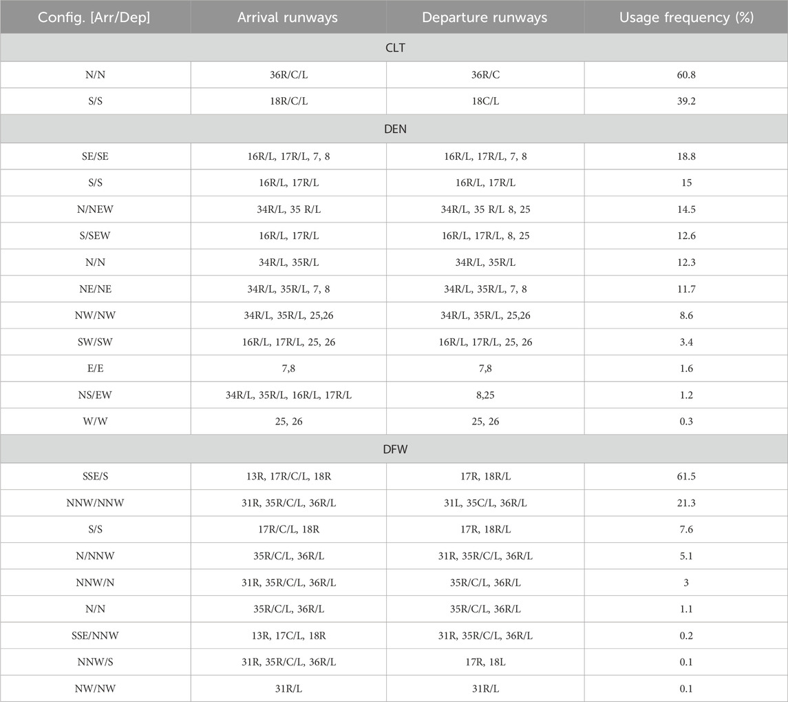
Table 1. The runway configurations for all three airports.
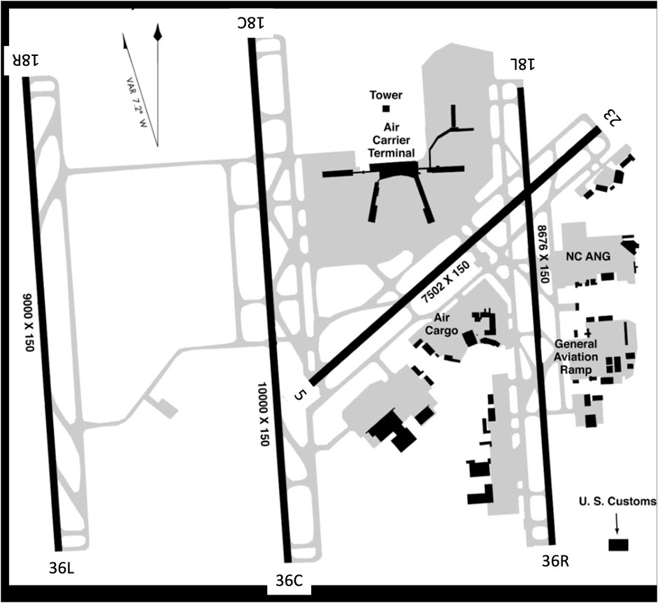
Figure 2. Charlotte douglas international airport surface diagram.
3.1 Monte Carlo random wind condition simulation
In the first part of our analysis, we randomly generate wind conditions to serve as input for the RCA tool. Wind conditions are sampled uniformly within the ranges of 0 knots to the maximum wind speed specified in Table 2 and 0–360° for wind direction. For each wind condition, we utilize the RCA tool to determine the recommended runway configuration. We then evaluate whether the tool output satisfied the established safety criteria, specifically focusing on crosswind and tailwind limits. This procedure is repeated 100,000 times for each airport (CLT, DEN, and DFW) to ensure a comprehensive analysis.
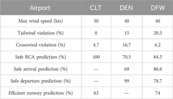
Table 2. Safety criteria of RCA tool prediction through randomly generated wind conditions.
To clarify this procedure, we look at three examples of runway configurations in different airports with random wind conditions. Figure 3 represents different wind conditions in three selected runways of different airports. The colored boxes indicate the safety criteria for the chosen runway configurations, each labeled in a format divided by dashes. The first segment of the label displays the takeoff configuration—
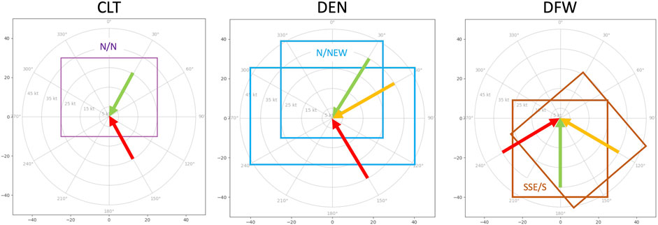
Figure 3. Safe and unsafe wind conditions on selected runway configurations for different airports. Each colored boxes represents the area satisfying the safety criteria. Two boxes in the middle and right subfigures show two different configurations for takeoff and landing. The first part in the box’s label represents the takeoff configuration and second one is for the landing. If the wind vector is shown in green, the selected runway configuration is safe for both takeoff and landing. A red vector indicates that the configuration is unsafe for both operations. A yellow vector signifies partial safety—safe for either takeoff or landing, but not both.
Table 2 shows the results of randomly generated wind condition simulation procedure. The results are calculated based on EG
3.2 Simulated daily wind transitions
In the second part of the analysis, we utilize actual weather data for years 2018 and 2019 to construct a transition matrix that describes changes in wind conditions throughout a day. This transition matrix provides a probabilistic framework for simulating realistic changes in wind conditions over time.
We estimate reasonable changes on an hourly basis in wind and meteorological conditions and simulate realistic operations (based on historical data), each multiple times to consider random variations. In each episode, the wind speed and direction, the hour of the day, and the meteorological conditions are sampled, and the RCA tool predicts the runway configuration.
3.2.1 Procedure
1. Random Day Selection: A day is randomly selected from the dataset.
2. Initial Condition: A random wind condition is chosen as the starting point for the simulation.
3. Simulation Process:
4. Safety Evaluation:
We showcase a series of figures depicting the simulated days in various scenarios. For CLT, we chose a randomly selected day. Similarly, for DEN and DFW, we selected and analyzed the most challenging scenarios involving random cases of tailwind and crosswind violations. We then compared these realistic scenario outcomes with those generated by Monte Carlo simulations. Each figure provides detailed information, displaying the mean and standard deviations calculated from 100 simulation iterations. This approach offers a comprehensive view of the variability of each scenario and the robustness of our simulation methodology in capturing the dynamics of runway safety under different wind conditions. Figure 4 illustrates a realistic simulation of a whole day in CLT. It captures fluctuations in wind speed and direction throughout the day, along with instances of tailwind violations. The depicted tailwind violation data represent the mean of 100 values, each coded as 0 or 1, where 0 indicates a safe scenario and 1 denotes an unsafe scenario. This provides a clear visual representation of the frequency and distribution of tailwind violations throughout the day.
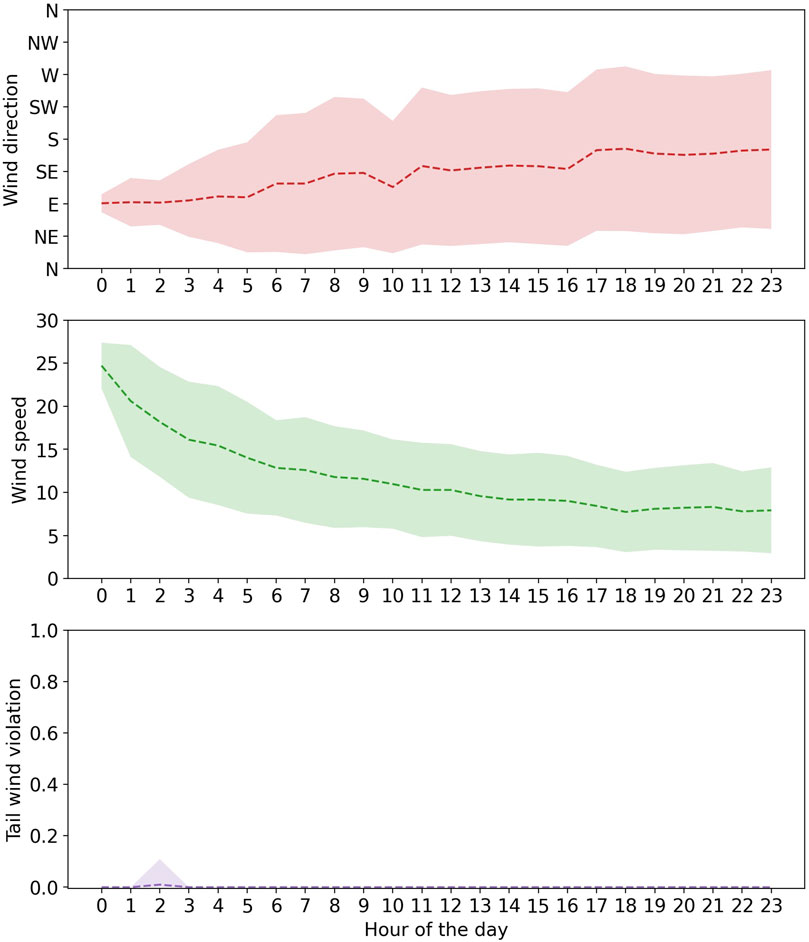
Figure 4. Realistic scenario simulation of CLT airport.
Figures 5, 6 show three different scenarios, worst-case scenarios of tailwind and crosswind violation, and a random one for DEN and DFW, respectively. The worst-case scenarios highlight instances of maximum safety violations within the system. By adjusting the predictions made by the RCA tool, we can effectively address and mitigate these violations. The tailwind and crosswind violations sub figures show that the model predictions decrease the safety violation throughout the day. The random scenario sub-figures also show significant low violations among 100 simulations during a day. The dashed line indicates the mean value, and the colored boundary shows the standard deviation.
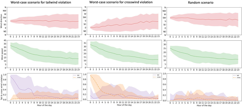
Figure 5. Realistic scenario simulation of DEN airport.
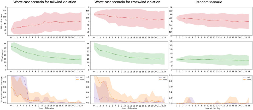
Figure 6. Realistic scenario simulation of DFW airport.
Table 3 shows the instances in which safety criteria are violated during both types of simulation. Notably, there is a significant reduction in the percentage of violations when comparing the results of Monte Carlo simulations to those from realistic scenarios. This indicates a marked improvement in the adherence to safety standards under more realistic operating conditions. This notable discrepancy between the two simulation scenarios, Monte Carlo and realistic, underscores the robustness and adaptability of our realistic simulation method, particularly in its superior ability to capture and respond to dynamic environmental variables when compared to the Monte Carlo simulations. This suggests that realistic simulation provides a more effective framework for understanding and managing complex real-world scenarios. The goal was to evaluate the performance of the model in predicting safe outputs over extended periods, reflecting realistic daily variations in wind conditions. This approach helps us understand how temporal changes in wind conditions impact the safety and reliability of the model’s predictions.
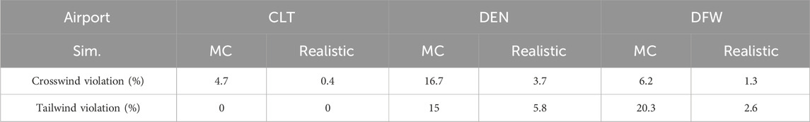
Table 3. Comparison between Monte Carlo (MC) and realistic simulations for all airports.
4 Conclusion
The application of formal verification methods to the RCA tool helps us validate the tool’s output in adhering to crucial safety criteria in air traffic control. This study underscores the value of using formal methods, such as model-checking, to rigorously assess the safety of machine learning algorithms within a safety critical operational setting. By validating the RCA tool’s compliance with safety criteria in various simulated wind conditions, the research highlights the potential of formal verification to enhance the trustworthiness of automated decision-support systems. The results of the Monte Carlo random wind condition simulations provided insight into the model’s ability to handle a wide range of wind speeds and directions, highlighting potential biases or limitations in handling extreme conditions. In addition, the simulations based on the (historical data-based) transition matrix offered a detailed view of the model’s performance in realistic and dynamic wind scenarios, revealing how well the model maintains safety standards throughout typical daily wind fluctuations.
It is worth to mention that while the RCA tool currently uses CQL with tabular representation and function approximators, future extensions to deep RL architectures could leverage abstractions or symbolic encodings (e.g., decision trees, BDDs) to preserve tractability in model-checking. Existing approaches in neural-symbolic verification (e.g., abstraction-refinement) could support scalability.
Data availability statement
The datasets presented in this article are not readily available because they are government classified data. Requests to access the datasets should be directed to the corresponding author.
Author contributions
PR: Investigation, Methodology, Software, Writing – original draft, Writing – review and editing. MM: Conceptualization, Supervision, Writing – original draft, Writing – review and editing. KK: Supervision, Validation, Writing – review and editing.
Funding
The author(s) declare that no financial support was received for the research and/or publication of this article.
Acknowledgments
We thank Subject Matter Experts (SMEs) affiliated with the FAA office of NextGen for their guidance and support in performing the validations.
Conflict of interest
Author PR was employed by Metis Technology Solutions, Inc.
The remaining authors declare that the research was conducted in the absence of any commercial or financial relationships that could be construed as a potential conflict of interest.
Publisher’s note
All claims expressed in this article are solely those of the authors and do not necessarily represent those of their affiliated organizations, or those of the publisher, the editors and the reviewers. Any product that may be evaluated in this article, or claim that may be made by its manufacturer, is not guaranteed or endorsed by the publisher.
References
AlSobeh, A. (2024). Osm: leveraging model checking for observing dynamic 1 behaviors in aspect-oriented applications. arXiv Prepr. arXiv:2403.01349.
Avery, J., and Balakrishnan, H. (2016). Data-driven modeling and prediction of the process for selecting runway configurations. Transp. Res. Rec. 2600, 1–11. doi:10.3141/2600-01
Badrinath, S., Li, M. Z., and Balakrishnan, H. (2019). Integrated surface–airspace model of airport departures. J. Guid. control, Dyn. 42, 1049–1063. doi:10.2514/1.g003964
Baheri, A., Ren, H., Johnson, B., Razzaghi, P., and Wei, P. (2022). A verification framework for certifying learning-based safety-critical aviation systems. AIAA Aviat. 2022 Forum, 3965. doi:10.2514/6.2022-3965
Bérard, B., Bidoit, M., Finkel, A., Laroussinie, F., Petit, A., Petrucci, L., et al. (2013). Systems and software verification: model-checking techniques and tools. Springer Science and Business Media.
Browne, C. B., Powley, E., Whitehouse, D., Lucas, S. M., Cowling, P. I., Rohlfshagen, P., et al. (2012). A survey of Monte Carlo tree search methods. IEEE Trans. Comput. Intell. AI games 4, 1–43. doi:10.1109/tciaig.2012.2186810
Gao, H., Huang, W., Liu, T., Yin, Y., and Li, Y. (2022). PPO2: location privacy-oriented task offloading to edge computing using reinforcement learning for intelligent autonomous transport systems. IEEE Trans. intelligent Transp. Syst. 24, 7599–7612. doi:10.1109/tits.2022.3169421
Jacquillat, A., Odoni, A. R., and Webster, M. D. (2017). Dynamic control of runway configurations and of arrival and departure service rates at JFK airport under stochastic queue conditions. Transp. Sci. 51, 155–176. doi:10.1287/trsc.2015.0644
Kumar, A., Zhou, A., Tucker, G., and Levine, S. (2020). Conservative q-learning for offline reinforcement learning. Adv. neural Inf. Process. Syst. 33, 1179–1191.
Li, L., Clarke, J.-P., Chien, H.-H. C., and Melconian, T. (2009). “A probabilistic decision-making model for runway configuration planning under stochastic wind conditions,” in 2009 IEEE/AIAA 28th digital avionics systems conference (IEEE), 3–A.
Li, Y., Li, Y., and Ma, Z. (2015). Computation tree logic model checking based on possibility measures. Fuzzy Sets Syst. 262, 44–59. doi:10.1016/j.fss.2014.03.009
Memarzadeh, M., Puranik, T. G., Kalyanam, K. M., and Ryan, W. (2023). “Airport runway configuration management with offline model-free reinforcement learning,” in AIAA SCITECH 2023 forum, 0504.
Nethi, S., Memarzadeh, M., and Kalyanam, K. (2024). “Optimization of runway configurations with forecast-augmented offline reinforcement learning,” in AIAA SCITECH 2024 forum, 0533.
Paul, S., Cruz, E., Dutta, A., Bhaumik, A., Blasch, E., Agha, G., et al. (2023). Formal verification of safety-critical aerospace systems. IEEE Aerosp. Electron. Syst. Mag. 38, 72–88. doi:10.1109/maes.2023.3238378
Razzaghi, P., Tabrizian, A., Guo, W., Chen, S., Taye, A., Thompson, E., et al. (2024). A survey on reinforcement learning in aviation applications. Eng. Appl. Artif. Intell. 136, 108911. doi:10.1016/j.engappai.2024.108911
Vardi, M. Y. (1996). “An automata-theoretic approach to linear temporal logic,” In Logics for Concurrency. Lecture Notes in Computer Science. (eds) Moller, F., Birtwistle, G. (Berlin, Heidelberg: Springer), 1043. doi:10.1007/3-540-60915-6_6
Appendix A. RCA-CTLogic Verification Algorithm
To complement the formal definitions and theoretical model-checking framework described above, Algorithm 1 outlines the complete verification procedure used to assess the safety of RCA tool outputs under varying wind conditions. The algorithm receives historical or simulated wind data as input, applies the RCA model to generate runway configuration decisions, and evaluates each decision against established crosswind and tailwind safety thresholds. The results are then analyzed using CTLogic to determine whether the model satisfies the temporal safety properties EF
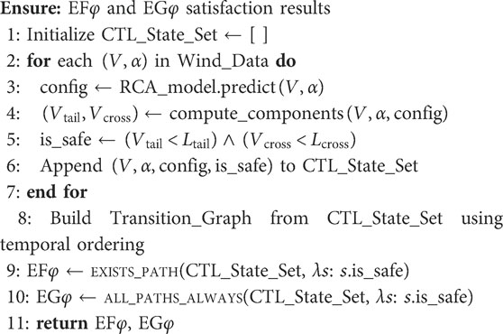
Algorithm 1. RCA-CTLogic Model Checking Algorithm.
Keywords: formal verification, model-checking, air traffic management, machine learning, safety criteria, runway configuration management
Citation: Razzaghi P, Memarzadeh M and Kalyanam K (2025) Formal verification of a machine learning tool for runway configuration assistance. Front. Aerosp. Eng. 4:1463425. doi: 10.3389/fpace.2025.1463425
Received: 11 July 2024; Accepted: 29 June 2025;
Published: 31 July 2025.
Edited by:
Kelly Cohen, University of Cincinnati, United StatesReviewed by:
Misagh Ketabdari, Polytechnic University of Milan, ItalyAnas AlSobeh, Southern Illinois University Carbondale, United States
Copyright © 2025 United States Government as represented by the Administrator of the National Aeronautics and Space Administration. At least a portion of this work is authored by Dr. Razzaghi, Dr. Memarzadeh, and Dr. Kalyanam on behalf of the U.S government and, as regards Dr. Razzaghi, Dr. Memarzadeh, and Dr. Kalyanam, U.S. copyright protection does not attach to separable portions of a Work authored solely by U.S. Government employees as part of their official duties. The U.S. Government is the owner of foreign copyrights in such separable portions of the Work and is a joint owner (with any non-U.S. Government author) of U.S. and foreign copyrights that may be asserted in inseparable portions the Work. The U.S. Government retains the right to use, reproduce, distribute, create derivative works, perform, and display portions of the Work authored solely or co-authored by a U.S. Government employee. Non-U.S copyrights also apply. This is an open-access article distributed under the terms of the Creative Commons Attribution License (CC BY). The use, distribution or reproduction in other forums is permitted, provided the original author(s) and the copyright owner(s) are credited and that the original publication in this journal is cited, in accordance with accepted academic practice. No use, distribution or reproduction is permitted which does not comply with these terms.
*Correspondence: Pouria Razzaghi, cG91cmlhLnJhenphZ2hpQG5hc2EuZ292