 Roberto Di Marco1,2*
 Samira G. Breban3
 Giuseppe Zullo3
 Francesca Gariboldi2,3
 Mattia Scapinello3
 Gian Luca Migliore2
 Nicola Petrone3
 Andrea G. Cutti2
- 1Department of Engineering for Innovation Medicine, University of Verona, Verona, Italy
- 2Centro Protesi, INAIL, Budrio, Italy
- 3Department of Industrial Engineering, University of Padova, Padova, Italy
Optimizing performance and safety in sprinters with lower-limb amputation requires standardized methods. This study presents a novel marker-based motion capture protocol to define local coordinate systems and Cardan sequences for in-vivo analysis of running biomechanics in athletes with transfemoral (TF) and transtibial (TT) amputation. The protocol provides detailed definitions and shares computational codes, supporting prosthetists and coaches in optimizing prosthetic setups. Moreover, integrating in-vivo biomechanics data into in-vitro and in silico experiments could lead to safer, more effective prosthetic designs. The methodology was tested involving two Paralympic gold medallists (one TF, one TT). To support global adoption and broad validation, all necessary computational tools, including kinematic calculation codes and model configuration files, are openly provided. These resources enable researchers to apply the protocol to various prosthetic setups and further test its applicability. By fostering global collaboration, this work lays the foundation for analysing Paralympic sprinting, optimizing athletic performance, improving prosthetic design, and advancing Paralympic sports biomechanics.
1 Introduction
Public interest in Paralympic sports is growing as recently demonstrated in Paris for the 2024 Games. This growth is driven by global events and the influence of social media, which are attracting more people with disabilities to participate in sports at highly competitive levels of athletes (Bouzas et al., 2021; Bragaru et al., 2011).
When considering persons with transfemoral (PTFA) or transtibial amputation (PTTA), athletic performances can be influenced by the components adopted in the athlete’s Running Specific Prosthesis (RSP) (Oudenhoven et al., 2017; Sakata et al., 2020) as well as by their set-up, also referred to as “prosthetic alignment” (Fletcher et al., 2021; Migliore et al., 2021). Both topics are actively investigated to allow Paralympic athletes safely compete at the highest level, delivering maximal performance without compromising their comfort and body integrity (Hadj-Moussa et al., 2022; Kent and Franklyn-Miller, 2011). Research methods include in-vivo quantitative collection of motion, followed by biomechanical data analysis (Alcantara et al., 2022; 2021; Day et al., 2021; Hobara et al., 2014; 2013; Makimoto et al., 2017; Nagahara et al., 2018; Taboga et al., 2020), component bench tests (Beck et al., 2016; Cutti et al., 2023; Dickinson et al., 2023; Gariboldi et al., 2023b; Gariboldi et al., 2023a; Gariboldi et al., 2022), and in silico simulations (Barattini et al., 2023; Murai et al., 2018; Rigney et al., 2015).
The biomechanical analysis of Paralympic athlete performances is crucial to deepen the understanding of both the athlete-prosthesis interaction, and the link between prosthesis set-up and performance. In the past decades, attention was paid to both kinematics and kinetics analyses. For sprinting, kinetics analyses call for expensive experimental set-up with force plates installed on track (Hobara et al., 2014; Hobara et al., 2013; Makimoto et al., 2017; Nagahara et al., 2018). These high costs have led to the adoption of the more cost-effective instrumented treadmill (Alcantara et al., 2022; Alcantara et al., 2021; Day et al., 2021; Taboga et al., 2020), allowing for data collection from many repetitions under highly controlled environments (Morin and Sève, 2011). However, treadmills have the drawback of not reproducing nor the top flying speeds nor the sprinting acceleration, which is a key element in understanding how athletes achieve high velocity (Maćkała et al., 2015), as well as altering the interaction with floor (tartan for sprinting tracks), aerodynamics and the perception of the surrounding space. Moreover, it imposes a single speed for both legs, while the body of a person using a prosthesis is clearly asymmetrical, with net braking impulses on the sound side and net propulsive impulse on the affected side (Breban et al., 2022).
Regarding kinematic analysis using marker-based stereophotogrammetry, most of the published studies focus on walking analyses (Hadj-Moussa et al., 2022; Kent and Franklyn-Miller, 2011). However, the approaches used in those studies cannot be adopted in sports assessments due to differences in the prostheses, particularly the running prosthetic feet. When defining marker-based kinematic models, some studies base the marker positioning on the prosthetic side on similarities with the sound limb, others associate markers to mechanical parts, and some use mixed approaches (Kent and Franklyn-Miller, 2011). Thus, no established motion analysis protocols (Kontaxis et al., 2009) exists for studying the kinematics of athletes with lower limb amputation in sports applications, resulting in data misinterpretation across studies and hampering the method’s use in assessing prosthetic function (Sawers and Hahn, 2010). Moreover, in vivo data collection is a key factor for setting up mechanical bench tests capable to reproduce real-world conditions to assess the functional characteristics of running specific components and sockets (stiffness) and their structural characteristics (ultimate strength and lifecycle). Component failure can indeed lead to prosthesis malfunction and potential athletes’ injuries (Gariboldi et al., 2022). Unfortunately, the lack of established motion analysis protocols limits the definition of standardized bench testing protocols, limiting the validity of the results across laboratories (Gariboldi et al., 2025a; Gariboldi et al., 2025b; Gariboldi et al., 2022).
In this framework, this study had three aims: 1) to propose a new method to concurrently assess in-vivo kinematics of running in athletes with TF and TT amputation, and inform bench test settings (e.g., relative position and orientation of prosthetic components, magnitude and directions of forces to be applied) of their prosthetic components; 2) to distribute to the research community the software needed to calculate the reference frames and joint angles proposed herein, ensuring transparency and reproducibility in biomechanical assessments; 3) to show two paradigmatic case studies, involving two Paralympic gold medallist with transfemoral (TF) and transtibial (TT) amputation.
2 Materials and methods
The following sections presents the nomenclature, the segments to be tracked, the marker positioning, the Local Coordinate System (CS) definitions and the Cardan sequences to be used to estimate joint kinematics.
Local Coordinate Systems (CS) were associated with each anatomical segment and prosthetic component, defining local pose matrices (position and orientation). Relative motion between segments or mechanical parts were computed starting from local pose matrices.
2.1 Terms, definitions, and notations
2.1.1 Prosthesis
A Running Specific Prosthesis (RSP) consists of a socket (the part that accommodates the residual limb), a prosthetic knee (in case of TF amputation) and a prosthetic foot, which for sports applications is hereinafter called Running Prosthetic Foot (RPF) as in (Petrone et al., 2020). Their relative position and orientation are set and maintained through “adapters” (clamps, hinge, pyramid or sliding joints with setscrews), and “pylons” (tubes of various length). Supplementary Figure 1 shows the typical configurations (assembled and exploded) of a RSP limb for TF (top side) and TT (bottom side) amputations.
Since RSP are modular systems, each component has a proximal and/or distal interface depending on its position in the serial connection. Among the connecting interfaces, two are particularly relevant for the prosthesis set-up, and, thus, for the definition of the motion analysis protocol: (i) the interface between the socket and its distal component is referred to as “socket-clamp”; (ii) the proximal interface of the prosthetic foot is named “foot-clamp”. In case of TT prosthetic limb, the socket-clamp and foot-clamp degenerate into a single foot-clamp.
The most used prosthetic knee in RSP is a mechanical monocentric knee joint (Ottobock 3S80, Ottobock GmbH, Duderstadt, Germany). It enables to adjust flexion and extension damping separately to ensure optimal control of flexion angles and extension during the swing phase of running. For elite running and sprinting, this is the only prosthetic knee used at present.
Although RPF shape may vary depending on the manufacturer, RPF presents either a C-shape or a J-shape (Figures 1–4). Theoretically, both shapes can be mounted on TT and TF RSP. However, since C-shapes are intended to be positioned under the socket, requiring sufficient height from the ground, they are mostly included in TF RSP. On the contrary, J-shapes are intended to be positioned posteriorly, in correspondence to the socket posterior box, which makes them ideal for direct connection to TT sockets. This is also the typical configuration for elite Paralympic athletes, and it will be the one we will refer to herein.
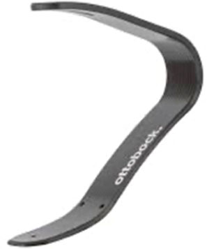
Figure 1. Running prosthetic foot 1E91, ottobock (Germany). https://www.ottobock.com/en-ex/product/1E91-60984.
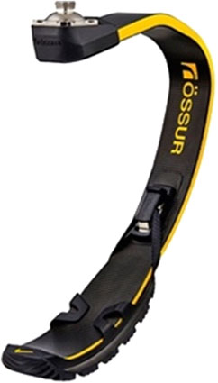
Figure 2. Running prosthetic foot Cheetah® xceed, ossur (Iceland). https://www.ossur.com/en-za/prosthetics/feet/cheetah-xceed.
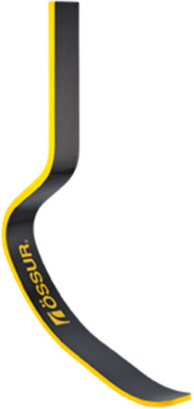
Figure 3. Running prosthetic foot Cheetah® xtreme, ossur (Iceland). https://www.ossur.com/en-gb/prosthetics/feet/cheetah-xtreme.
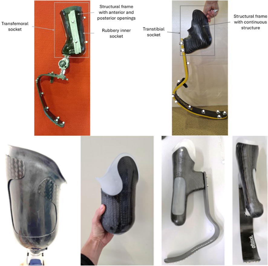
Figure 4. Flexible sockets for people with transfemoral (two leftmost pictures) and transtibial (two rightmost pictures) amputations.
2.1.2 Coordinate systems
All CSs are defined by a right-handed orthonormal
Human or mechanical joints are instead labelled with their names’ lowercase first letter (e.g., cervical is
Points (in uppercase), vectors (in lowercase) and matrices (uppercase bold text) are labelled with a left superscript to address the CS they are defined into, and a right subscript to identify the CS they are referred to. For example:
•
•
•
•
•
2.2 Segments, landmarks, markers, coordinate systems
This section and the Supplementary Material present the definition of each segment, together with its landmarks and the relevant markers used for their tracking (Cappello et al., 1997), and the CS.
Sound-side segments definitions follow the ISB recommendations (Wu et al., 2002), and include head, trunk, pelvis, thigh, shank, and foot. The upper limbs are also included through a simplified two-segment description, one for upper arm and one for the forearm, considering that their motion takes place mostly on the body quasi-sagittal plane during running, with the elbow not extended (Hamner et al., 2010; van Oeveren et al., 2024). Since these definitions are based on known literature, they are provided in the Supplementary Section 2, while those for the prosthetic side are included herein.
Prosthetic side segments include socket, prosthetic knee, and RPF, which is assumed to be formed by two sub-segments, the proximal portion (solid with the foot-clamp) and the distal tip portion (the distal-most 5 cm of the running blade). The relative motion of these two sub-segments accounts for the RPF large deformations during running stance.
Figures 5, 6 and Tables at the beginning of each 2.2.x paragraph and Supplementary Table 17 report the full marker-set for two athletes, one with a TF amputation at the right lower limb and one with a TT amputation at the right lower-limb. Markers can be either:
• Physical: when associated with a visible marker and attached to a landmark;
• Virtual: a body internal point, which can be reconstructed based on regression methods–e.g. the hip joint centre (Bell et al., 1990) – or arithmetical calculations–e.g. the knee joint centre, obtained as the midpoint between lateral and medial markers. Since those are internal points, they are not associated with any physically attached markers.
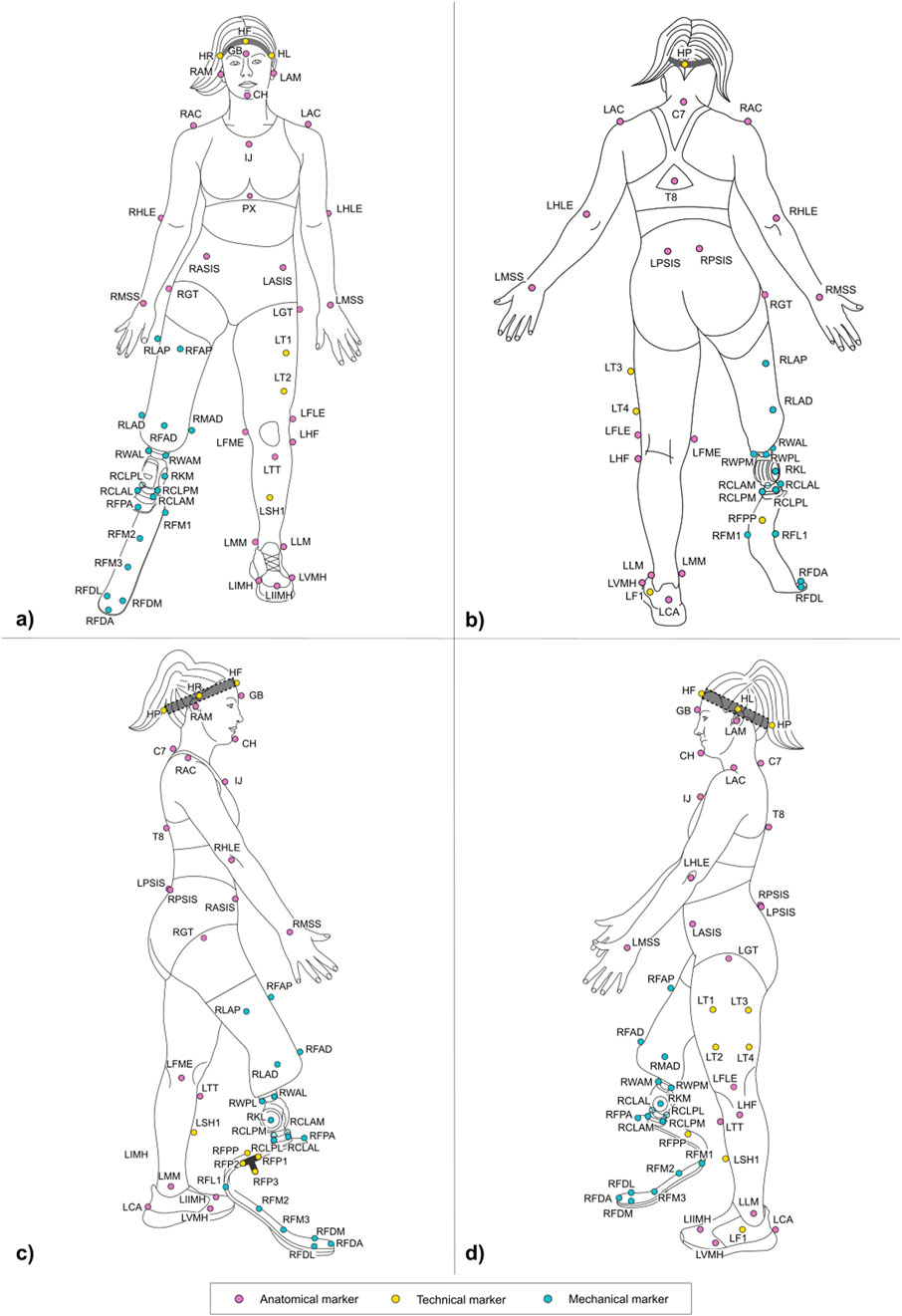
Figure 5. Frontal (a) posterior (b) lateral right (c) and lateral left (d) view of the full marker-set applied on an athlete with a TF amputation on the lower-limb. Markers can be anatomical (light magenta), technical (yellow), and mechanical (light blue). Head markers (HF, HR, HL, HP) are placed on an elastic headband.
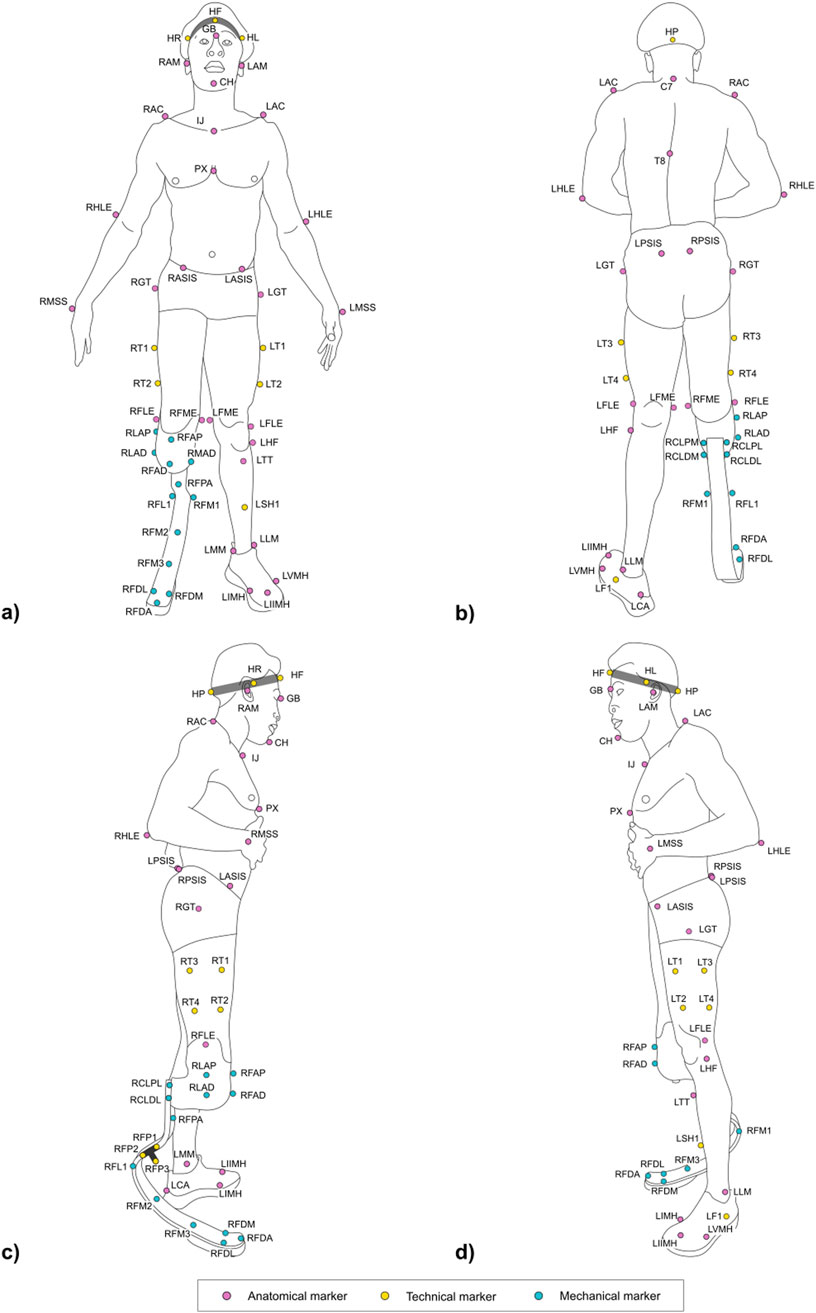
Figure 6. Frontal (a) posterior (b) lateral right (c) and lateral left (d) view of the full marker-set applied on an athlete with a TT amputation on the lower-limb. Markers can be anatomical (light magenta), technical (yellow), and mechanical (light blue). Head markers (HF, HR, HL, HP) are placed on an elastic headband.
Markers can be further classified into three types, namely:
• Anatomical: physical or virtual marker associated with an anatomical landmark;
• Mechanical: physical or virtual marker associated with a geometrical landmark (also referred to herein as “mechanical landmark”) of a mechanical component;
• Technical: a physical marker needed to reconstruct the position of calibrated anatomical or geometrical landmarks through a static trial (Cappozzo et al., 2005); these markers are attached to the segment to ensure their traceability, i.e. they are not necessarily attached to a clearly defined landmark. A group of technical markers attached to the same segment is named as “technical cluster.”
Anatomical and mechanical markers can then pertain to three classes:
• permanent: a physical marker that will stay on the subject’s body or RSP throughout the whole data acquisition process. A marker pertains to this class if not otherwise specified.
• Static: a physical marker that is detached from the subject or the RSP after completion of a static (standing) calibration trial following the approach reported in (Cappello et al., 1997). These are denoted with an “S” in the Tables containing the marker list.
• Wand-calibrated: wand-calibrated markers are not physically placed on the subjects but are pointed with a marker-equipped wand of known geometry, following the approach reported in (Cappello et al., 1997). Landmarks palpated with the wand tip are then reconstructed with respect to the markers on the wand itself and, eventually, made solid with the segment cluster the pointed markers refer to. These are denoted with a “W” in the Tables containing the marker list.
The protocol follows the CAST approach (Cappozzo et al, 1995). Each subsection describing a segment and Supplementary Section 2 report the CSs definitions. To ease their understanding, Figures 7–10 provide a visual representation of CS construction. Axes x, y and z are coloured following the RGB code. In addition, the order of construction of the CS axes is indicated by a number in brackets next to the axis name: e.g. x (1), z (2), y (3) indicates that the first axis of the CS to be defined is x, followed by the definition of z, to conclude with the definition of y. Finally, relevant construction planes based on markers are also provided, with their colour matching that of the axis to which they are perpendicular.
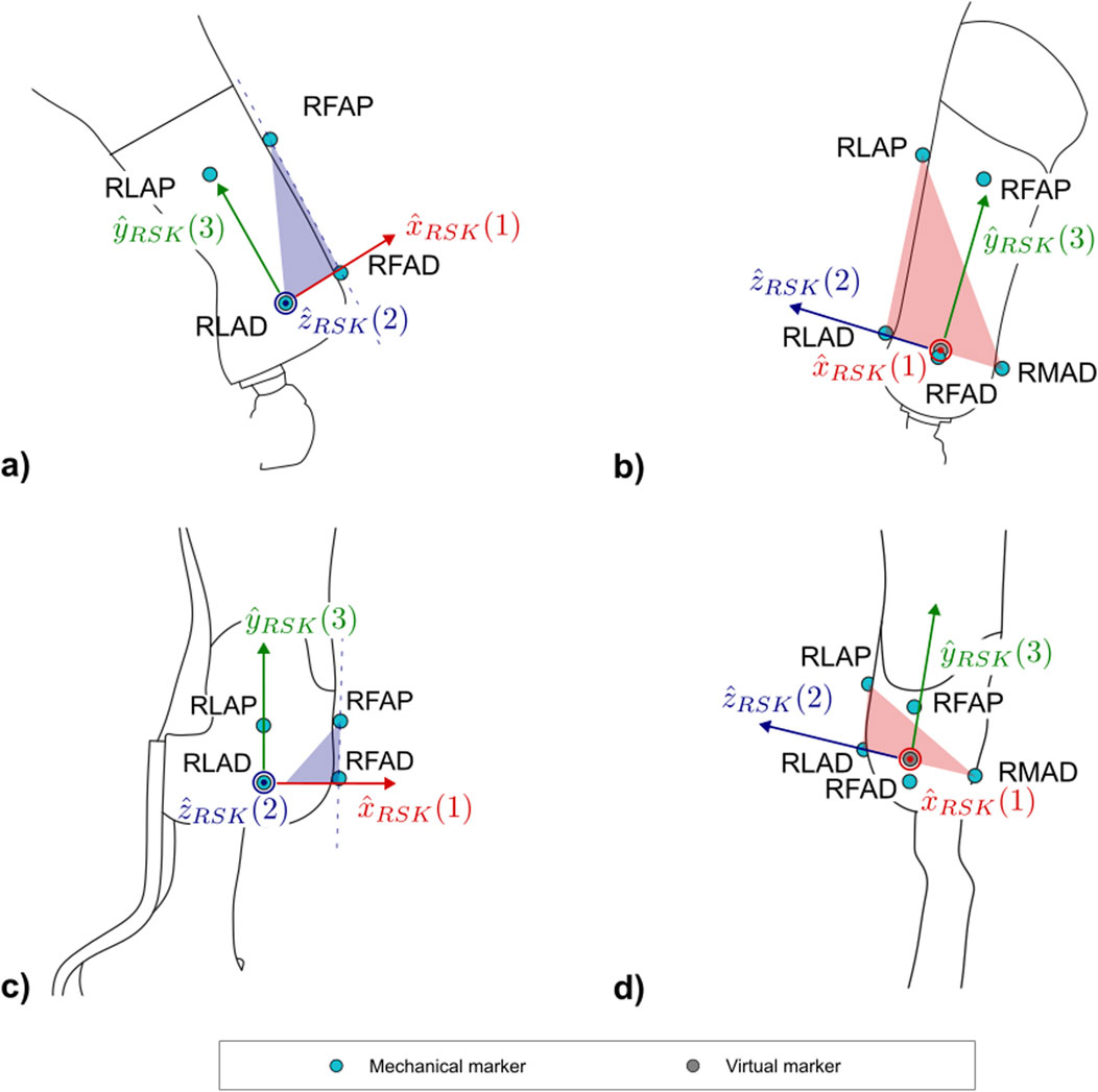
Figure 7. Markers and local coordinate system definitions of: (a) right lateral and (b) frontal views of the socket for PTFAs; (c) right lateral and (d) frontal views of the socket for PTTAs. Light blue markers are mechanical, while virtual calculated points are in grey.
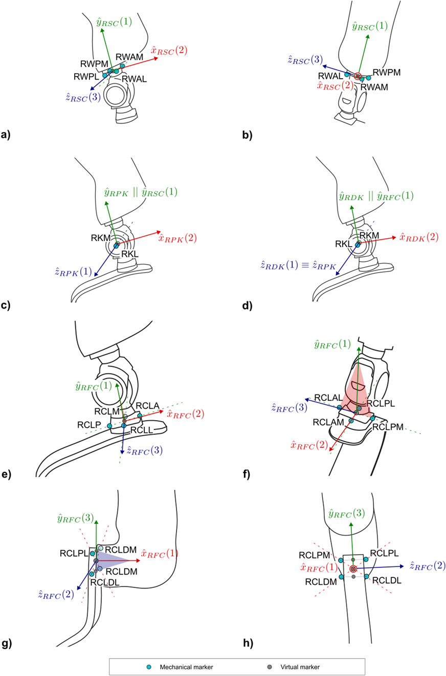
Figure 8. Markers and local coordinate system definitions of: (a) right lateral and (b) frontal views of the socket-clamp for PTFAs; (c) right lateral view of the proximal prosthetic knee and (d) distal prosthetic knee for PTFAs; (e) right lateral and (f) frontal views of foot-clamp for the PTFAs; (g) right lateral and (h) frontal views of the foot-clamp for PTTAs. Light blue markers are mechanical, while virtual calculated points are in grey.
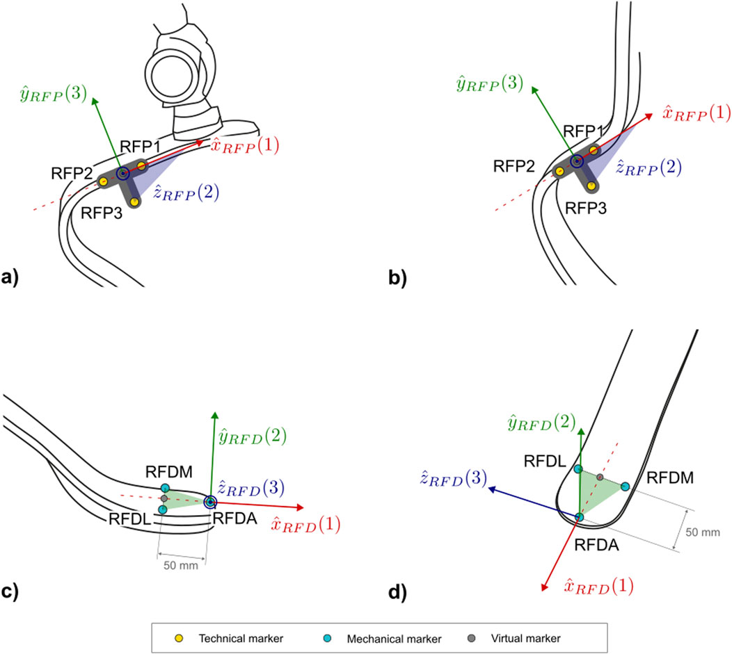
Figure 9. Markers and local coordinate system definitions of: the technical proximal running prosthetic foot (right lateral view) for TF (a,b) PTTAs; and (c) right lateral and (d) frontal views of the distal portion of the running prosthetic foot for the TF and PTTAs. Light blue markers are mechanical, while virtual calculated points are in grey.
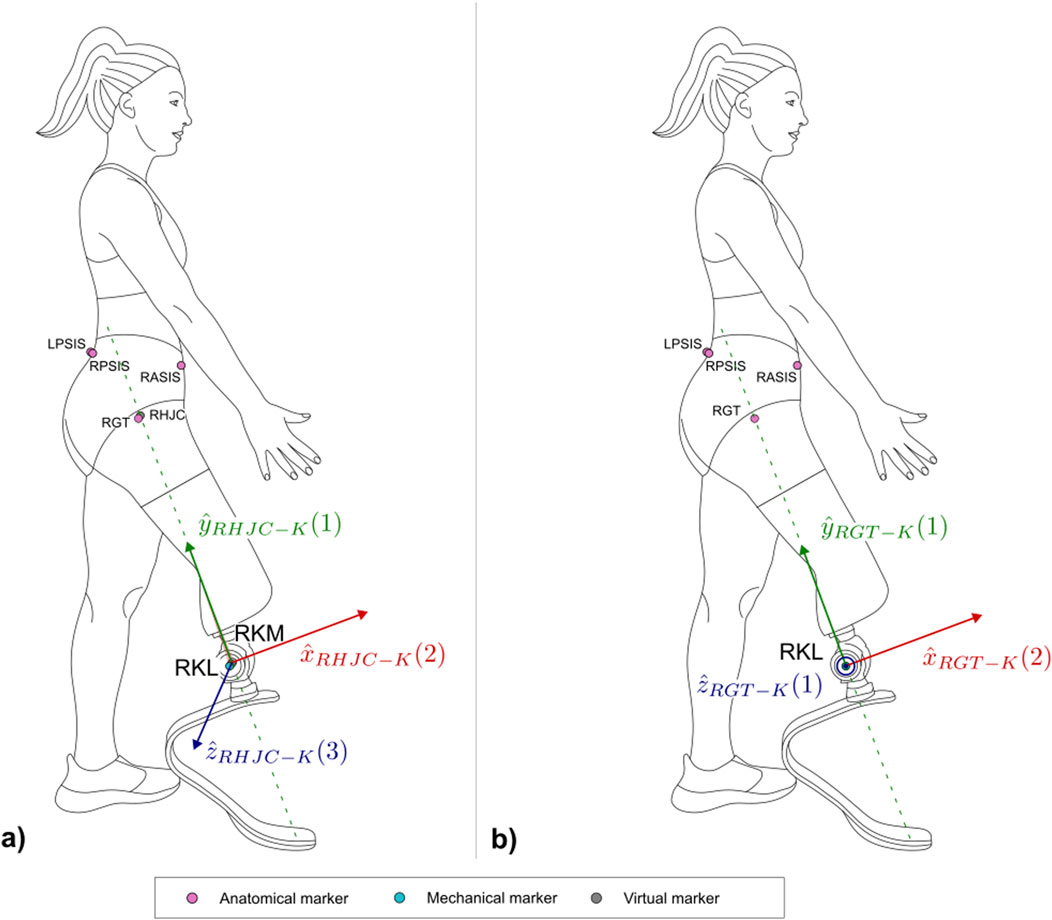
Figure 10. Right lateral view of the three-dimensional (a) and two-dimensional (b) systems built on the limb wearing the running specific prosthesis with the markers. Light magenta markers are anatomical, light blue markers are mechanical, while virtual calculated points are in grey.
2.2.1 Socket
Lower limb sockets included in RSP have a bespoken shape to accommodate the specific athlete’s anatomy and component alignment and consist of a carbon fibre laminated frame that provides the mechanical strength to support the high demanding activities (Figure 4). The laminated frames can either fully enclose the residual limb in a closed structure or feature large anterior and/or posterior openings (“windows”) that expose an inner flexible socket made of thermoplastic material (e.g. ethylene-vinyl acetate).
In order to adapt to both closed and windowed sockets and account for the socket clamp placed behind it in case of PTTA, the reference system will be mainly constructed from markers placed on the lateral and medial sides of the socket, which normally have a cylindrical or conical shape (Table 1).
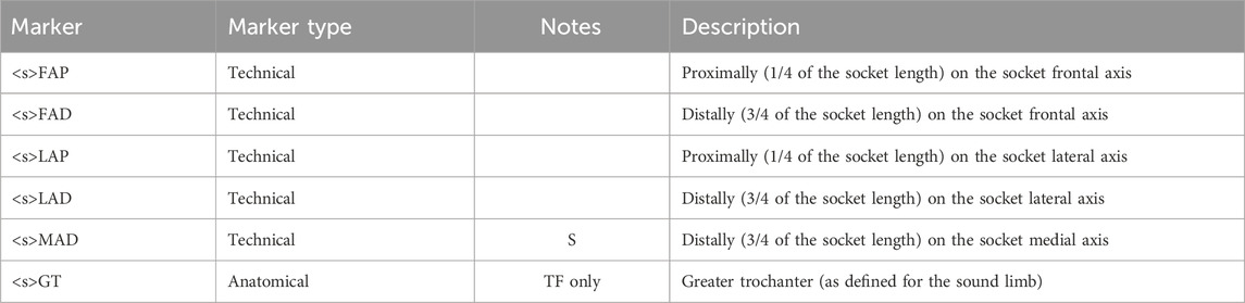
Table 1. List of markers used for the socket segment.
Markers position depends on the knowledge of the socket frontal and lateral axes, as established by a certified prosthetist when the athlete dons the RSP. No established international standard exists that defines the frontal and lateral axes of the socket. To tackle this relevant limitation, a procedure is reported in Supplementary Section 3, based on current clinical practice and extensive discussions within the ISO Standardisation committees TC168 WG1 and WG3.
The definition of the socket CS (abbreviated as SK and shown in Figure 7) is based on the points LAP, LAD, MAD. The proposed definition of the CS ensures consistency with the 2D definition of the same CS: i.e., the longitudinal axis of the socket leans on the LAP-LAD-MAD defined plane and is perpendicular to
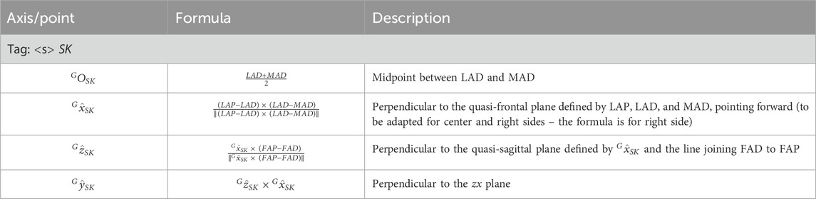
Table 2. Socket coordinate system definition.
2.2.2 Socket-clamp–TF
Supplementary Figure 2 shows an example of socket clamp used in TF sockets. It is a squared, 4-screw adapter placed distally to the socket. This CS is essential for transferring ground reaction forces and moments to the interface between the clamp and the socket, to support bench tests definition.
The following markers are intended to be solid with the cluster placed on the socket composed by FAP, FAD, LAP, LAD, and MAD markers. Indeed WAM, WAL, WPM and WPL landmarks are wand-calibrated with respect to the socket technical cluster (Table 3).
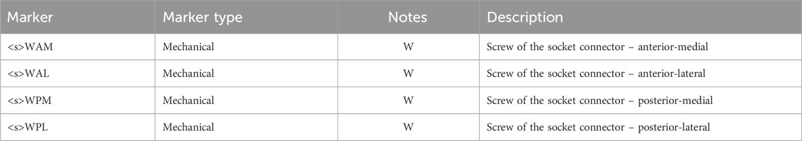
Table 3. List of markers used for the socket-clamp segment in PTFAs.
The definition of the socket-clamp coordinate system (abbreviated as SC and shown in Figure 8) is based on the points WAL, WAM, WPL, WPM (Table 4).
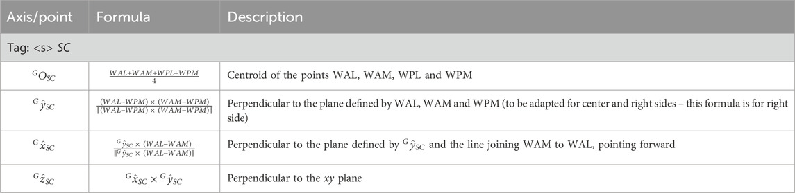
Table 4. Socket-clamp coordinate system definition in PTFAs.
2.2.3 Prosthetic mechanical knee–PTFAs
Two coordinate systems have been defined to capture the flexion angle of the prosthetic mechanical knee: a proximal and a distal functional knee coordinate system (Kontaxis et al., 2009). Particular attention is given to defining the shared axis of flexion, which both coordinate systems have in common. This shared axis is the reason why the coordinate systems are referred to as “functional”. Notably, the markers used to define this axis (KL and KM–Table 5) are measured directly by the optoelectronic system and should not be reconstructed with techniques such as singular value decomposition relative to other segments (Cappozzo et al., 2005). This allows avoiding cluster deformation effects, with consequent marker trajectory mis-reconstruction, which may introduce undesired crosstalk in kinematics estimation.
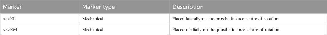
Table 5. List of markers used for the prosthetic mechanical knee in PTFAs.
2.2.3.1 Proximal prosthetic knee functional CS
The Proximal Prosthetic Knee Functional CS is defined starting from the knee flexion axis in combination with the socket-clamp coordinate system (Table 4). The definition of the proximal functional knee coordinate system (abbreviated as PK and shown in Figure 8c) is based on the points KM, KL and the pseudo-vertical axis of the socket-clamp coordinate system (Table 6).
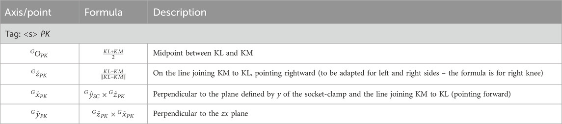
Table 6. Proximal prosthetic functional knee coordinate System definition.
2.2.3.2 Distal prosthetic knee functional CS
The Distal Prosthetic Knee Functional CS is defined starting from the knee flexion axis and the foot-clamp CS (Table 12). The definition of the proximal functional knee coordinate system (abbreviated as DK and shown in Figure 8d) is based on the points KM, KL and the pseudo-vertical axis of the foot-clamp coordinate system.
Since the pylon and/or pyramid adapters proximal and distal to the prosthetic knee are not necessarily aligned, the flexion angle does not necessarily equal 0 when the mechanical knee is completely extended. The offset should be reported over the dynamic time history of the prosthetic knee flexion/extension angle (Table 7).
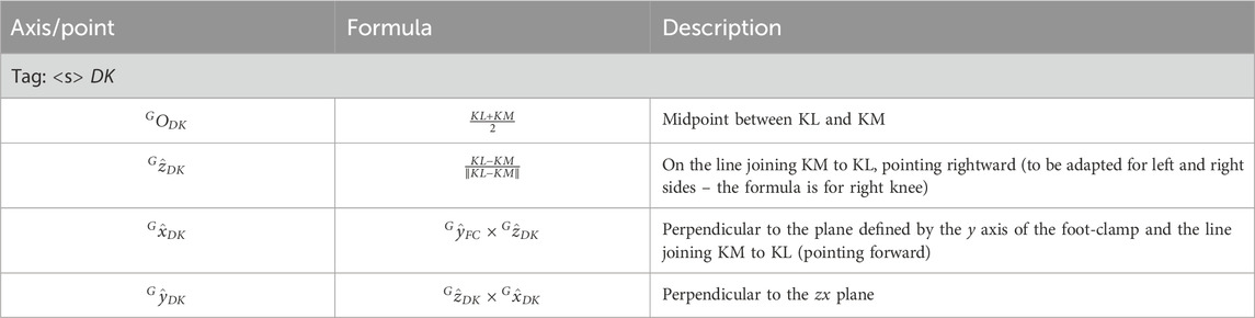
Table 7. Distal prosthetic functional knee coordinate system definition.
2.2.4 Running prosthetic foot clamp
2.2.4.1 C-shaped RPF
C-shaped RPF can differ on clamp geometry depending on the manufacturer (Supplementary Figure 3). This protocol proposes strategies to adapt the biomechanical model to as many clamp types as possible, so to identify the axis normal to the clamp plane and the tangent to the proximal portion of the RPF lying on the sagittal symmetry plane of the RPF.
In the case of a sliding pyramid adapter foot-clamp (Supplementary Figure 3a) such as the one of Ottobock Runner RPF, markers are placed on a custom 3D printed “crossed-shaped collar support” (Supplementary Figure 3b), which is rigidly connected to the clamp with set screws. Once in place, the markers on the collar lay on a plane parallel to the clamp-RPF interface. The collar support is needed as there would not be enough room to directly attach markers on the foot-clamp support. The STL file to replicate the collar support for the Ottobock Runner RPF is provided as an example in Supplementary Section 1.1.
In case of 4-hole pyramid adapter foot-clamps (Supplementary Figure 3b-d), mechanical landmarks needed to build the local CS are wand-calibrated following the configuration given in Table 4, as the interface between the foot-clamp and the foot is secured with screws via through-holes. These landmarks are calibrated relative to a custom 3D printed T-shaped rigid support that host three technical markers and that is attached laterally to the RPF immediately posterior to the foot clamp. A technical Coordinate System can be defined for this T-shaped support, named Technical Proximal Running Prosthetic Foot, as reported in Section 2.2.6.1. The STL file to replicate the T-shaped support is provided in Supplementary Section 1.1.
Markers <s>CLA, <s > CLM, <s> CLL and <s> CLP are then obtained as follows (the <s> is omitted in the formulas for simplicity) (Table 8):
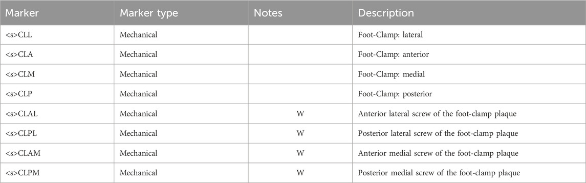
Table 8. List of markers for the foot-clamp segment in PTFAs.
The definition of the foot-clamp coordinate system for PTFAs (abbreviated as FC and shown in Figures 8e,f) is based on the points CLA, CLM, CLL, CLP (Table 9).
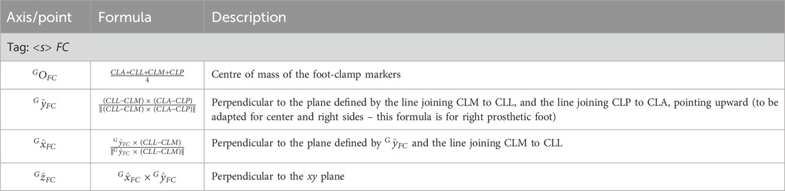
Table 9. Foot-clamp coordinate system definition in PTFAs.
2.2.4.2 J-shaped RPF
For J-shaped RPF, 4 markers are used to define the foot-clamp CS. Markers are applied to the lateral and medial side of the RPF in its most proximal part of the RPF (Figures 4, 6) at the same height of the two screws that connect the foot to the socket posterior box (Table 10).
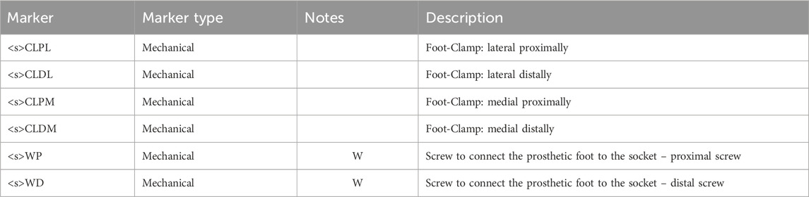
Table 10. List of markers used for the foot-clamp segment in PTTAs.
The definition of the foot-clamp coordinate system (abbreviated as FC and shown in Figures 8g,h) is based on the points CLPM, CLPL, CLDM, CLDL (Table 11).
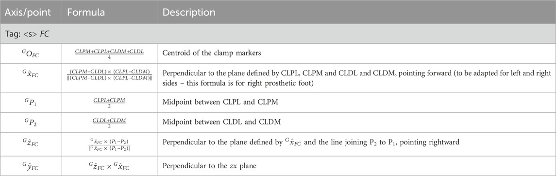
Table 11. Foot-clamp coordinate system definition in PTTAs.
2.2.5 Distal running prosthetic foot
The definition of the distal portion of the running prosthetic foot coordinate system (abbreviated as FD and shown in Figure 9b) is based on the points FDA, FDM, FDL (Tables 12, 13).
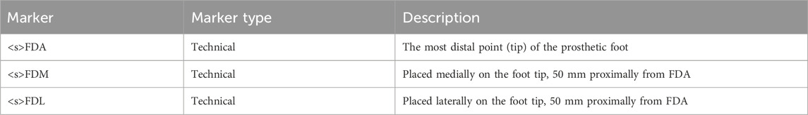
Table 12. List of markers used for the distal running prosthetic foot.
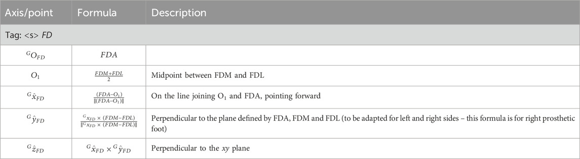
Table 13. Distal prosthetic foot coordinate system definition.
2.2.6 Auxiliary CS
2.2.6.1 Technical proximal running prosthetic foot
As anticipated in Section 2.2.4.1, this technical coordinate system is built on the technical cluster consisting of the markers FP1, FP2 and FP3 (Table 14). This CS (Figures 9a,b) is not used to compute any joint kinematics during the exercise, but shall the prosthetist change the position of the foot-clamp with respect to the RPF, by keeping the triad fixed on the RPF across the trials, this system allows measuring differences among alignments due to different configurations. Additionally, in case of visibility loss for other markers on the foot-clamp or wand-calibrated markers of the foot-clamp, this cluster triad enables the reconstruction of those markers’ trajectories.
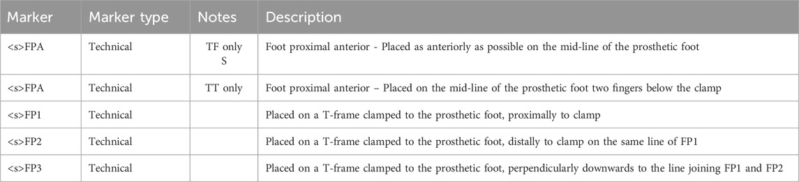
Table 14. List of markers used for the technical proximal portion of running prosthetic foot segment.
The definition of the technical system of the proximal running prosthetic foot coordinate system (abbreviated as FP and shown in Figures 9a,b) is based on the points FP1, FP2, FP3 (Table 15).
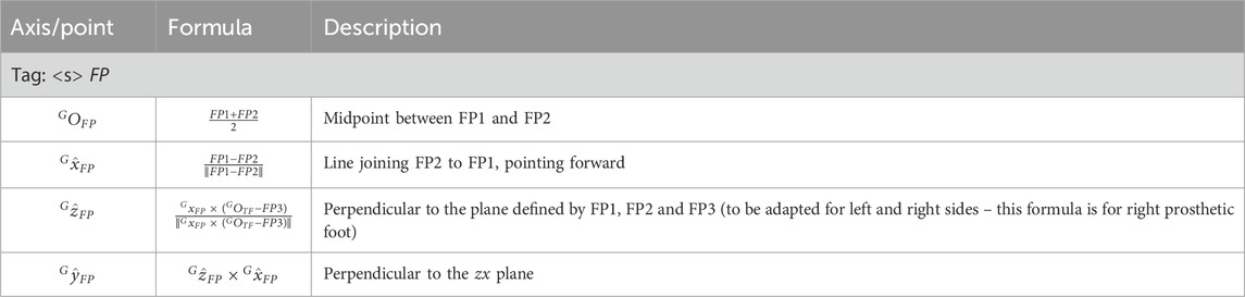
Table 15. Technical proximal RPF coordinate system definition.
The <s>FPA markers are not intended to be used for CS definition but are considered as part of the technical cluster of the RPF in case of marker’s trajectory occlusion. Moreover, the relative motion of the <s>FDA marker (on the tip of the distal portion of the RPF) with respect to the <s>FPA can be informative of the actual RPF compression.
2.2.6.2 Equivalent leg systems
The two following CSs are defined to build an equivalent mechanical segment of the thigh in PTFAs as a whole and to attempt modelling an equivalent mechanical axis used for alignment of the RSP components during production and bench tests by the prosthetist, especially for socket testing (Migliore et al., 2021). Moreover, tracking the trajectory of the RPF tip with respect to the CSs defined in the following paragraphs would provide a measure of the “feeling” of the athletes during their performances (Hansen et al., 2004). The first CS is defined as a 3D system, whereas the second is a 2D system to be used to compare data gathered via stereophotogrammetry with those collected with high rate and high-resolution video recordings.
2.2.6.2.1 HJC-K coordinate system definition (3D system)
The definition of the HJC-K coordinate system (Figure 10a) is based on the points HJC, KM, KL (Table 16).
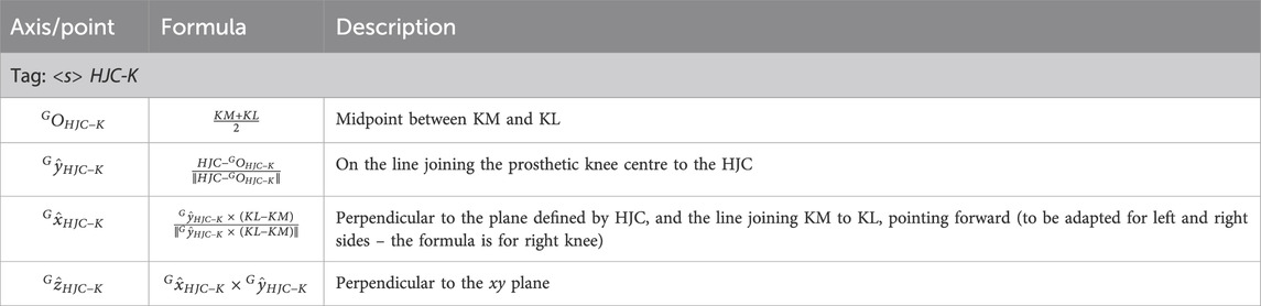
Table 16. Auxiliary 3D coordinate system definition based on the line connecting the hip joint centre to the prosthetic knee centre.
2.2.6.2.2 GT-KL coordinate system definition (2D system)
This reference system, analogous to the previous one, is useful for a direct comparison with a video analysis, where the traces of HJC and the midpoint between KM and KL are not available, but an approximation of their external projections are rather captured (i.e., GT and KL).
The definition of the GT-KL coordinate system (Figure 10b) is based on the points GT, KL (Table 17).
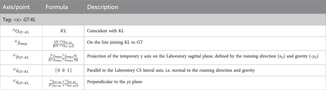
Table 17. Auxiliary 2D coordinate system definition based on the line connecting the lateral approximation of the hip joint centre (i.e., the great trochanter) to the lateral projection of the prosthetic knee centre (i.e., the lateral knee marker).
2.3 Kinematics–cardan sequences
Joint kinematics is obtained as decomposition of the relative rotations between adjacent segments and following the International Society of Biomechanics recommendations (Wu et al., 2005; 2002; Wu and Cavanagh, 1995), based on the Cardan convention originally proposed by Grood and Suntay for the lower limb joints to associate a clinical meaning to the obtained rotations (Grood and Suntay, 1983). Detailed definition of the Cardan sequences to decompose the relative rotation matrices are given in Supplementary Table 18. The zx’y’’ sequence was used to decompose all joint relative rotation matrices, except for ankle and virtual ankle (i.e., the relative orientation of the distal portion of the RPF with respect to the foot-clamp coordinate system) where the chosen sequence was zy’x’’.
Segment orientation is obtained decomposing the rotation matrix of each local embedded coordinate system with respect to the ground coordinate system and considering a roll-pitch-yaw convention.
2.4 Data collection procedure
The preparation process starts by drawing the main socket lines as described in paragraph 2.2.1 and the subsequent marker placement on the RSP (socket, knee -if any- and RPF). Afterward, the athlete’s skin is prepared to ensure proper adhesion of tapes and markers by gently scrabbing with alcoholic wipes. Pre-taping and Kinesiotape are then applied to the athlete’s skin and the areas of the running shoes over anatomical and technical landmarks. Following this step, anatomical and technical landmarks are palpated and marked with a pen and subsequently markers are physically placed on the athlete, using a highly adhesive double-sided tape. Palpation takes advantage of the athlete’s verbal feedback when dealing with anatomical landmarks of the foot in the shoe. The athlete then undergoes a warm-up session, which is crucial for becoming accustomed to the markers and allowing full focus on performance. Experience suggests that placing retroreflective markers before the warming up reduced their detachment, rather than letting them warm up and placing markers subsequently because of perspiration. After the warm-up, markers are checked and adjusted, if necessary. The total preparation time, excluding the warm-up, is approximately 25 min. However, since the prosthesis preparation can occur independently of the athlete’s direct involvement, the impact on the athlete’s preparation time is around 20 min.
Static measurements are then collected with the athlete standing upright. After the static standing trial, an operator proceeds by collecting separate static trials for each of the wand-calibrated markers, using a marker-equipped wand (5 min). Finally, dynamic assessments are performed, with their duration depending on the specific data to be captured. Appropriate resting time must be granted among trials based on the athlete’s and their coach feedback.
2.5 Data analysis
Marker trajectories collected during standing and running are pre-processed as per motion capture routinary pipeline: reconstructed, labelled and gap filled and smoothed within the software of the optoelectronic system, e.g. Vicon Nexus for our set-up (version 2.13+, Vicon Motion Systems Ltd., Oxford, UK), as well as the manual foot-strike and foot-off event detection.
Once these preliminary steps are completed, 1) virtual and calibrated markers are localized with respect to their relevant clusters using regression methods (Bell et al., 1990), and data from wand trials (Cappello et al., 1997), respectively. Then, 2) they are reconstructed in a static trial containing all the physical and calculated markers. Thereafter, 3) all virtual and static-only markers from the processed static trial are reconstructed in dynamic trials using the singular value decomposition approach (Cappozzo et al., 2005). Finally, 4) local coordinate systems construction and kinematics calculations are completed for each static and dynamic trial, following the definitions provided in this paper. Joint kinematics are time-normalized over the stride percentage (with 0% and 100% being subsequent foot-strike of the same side).
2.6 Olympia open-source software
Steps 1) to 4) as described in Section 2.5, are complex and would typically require the implementation of a custom-made software. This is a time-consuming operation and would require specific technical knowledge. This requirement can limit the diffusion of the protocol among the interested researchers. For this reason, alongside the manuscript, we are providing a MATLAB open-source implementation of the software, called Olympia, needed to complete the steps.
Assuming the data collection procedure described in Section 2.4, the Olympia software was designed to compute segmental and joint kinematics based on the definition of the biomechanical model, starting from pre-labelled static, calibration, and dynamic files. The system incorporates sufficient flexibility and adaptability to address the typical challenges encountered during real-life data collection.
Specifically, during the same data collection session, the RSP setup may change between trials for clinical or research purposes. This results in a change of configuration, requiring the entire data collection procedure to be restarted as described. Also, even if the prosthetic configuration remains unchanged, it is possible that one or more markers detach from the participant’s skin or from the RSP. In such cases, a new static trial must be collected. If a detached marker belongs to a cluster associated with wand-calibrated markers, those wand-calibrated markers must also be recalibrated after the new static trial.
2.7 Example dataset
To ensure that Researchers can practice with the Olympia software, an exemplary dataset on sprinting tests is provided alongside the source codes.
Specifically, the data collection protocol was used as part of the standard assessment routine and training during the 2023–2024 Paralympic season to support certified prosthetists in setting up the RSP for the elite sprinters in preparation of the Paralympic Games in Paris. The written consent to diffuse their data together with the Olympia software was obtained by two gold medallists, respectively with a TF and TT amputation.
The TF (female, mass: 55 kg, height: 1.60 m) is a T63 100 m medallist in Paris 2023 World Para Athletics Championships, who uses a 1E91 Standard Runner Cat 4 RPF (Ottobock, Germany) and 3S80 monoaxial prosthetic knee joint (Ottobock, Germany) on her left prosthetic leg. With reference to (Migliore et al., 2021), the socket tilt in the sagittal plane relative to the gravity was 15°.
The TT (male, mass: 85 kg, height: 1.87 m) is a T64 100 m medallist in Paris 2023 World Para Athletics Championships, who used as RPF a Sprinter Cat 4 (Ottobock, Germany) on his left prosthetic leg.
Tests were performed and recorded at the “Olympia SmartTrack” installed at the “Palaindoor Padova”, which consists of: (i) a 13.0 × 7.0 × 3.5 m3 portal to carry the (ii) 10-IR camera stereophotogrammetric system (Vicon Vantage V5, Vicon Motion Systems Ltd., Oxford, UK), and (iii) nine force plates (two BMS400600 and seven BMS600900, AMTI Advanced Mechanical Technology, Inc., Watertown, MA, USA) (Mistretta et al., 2022).
Both athletes were asked to run over a 60 m straight path. The camera configuration ensures a capture volume of approximately 7.0 × 3.0 × 2.0 m3. The portal and the force plates are positioned 30 m from the start line to allow for the collection of athletes’ steady-state running data.
3 Results
3.1 Olympia software architecture and procedure
The Olympia Software is publicly available at the URL https://www.doi.org/10.5281/zenodo.15537123. While referring the reader interested in the full details to Supplementary Section 7, we reported herein a brief explanation of the software architecture. Specifically, the processing flow is shown in Figure 11.
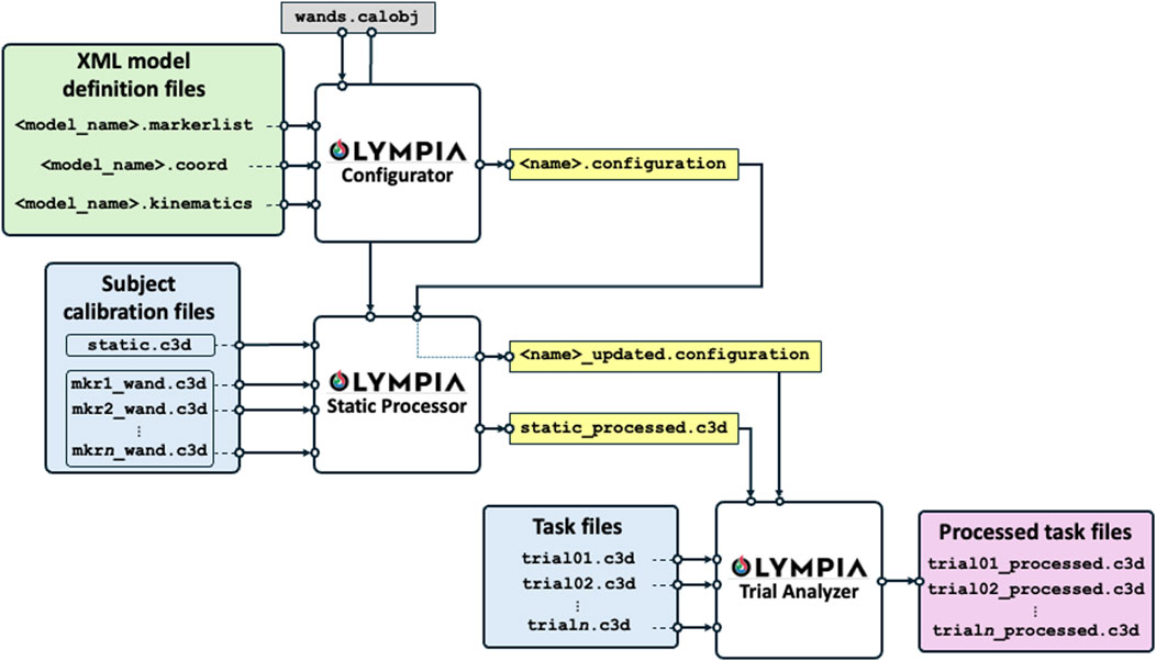
Figure 11. Software data and processing flow. The green box contains the proposed model definitions (or given according to any other biomechanical model to be adopted). The white boxes are the functional blocks of the software to process the data. The light blue boxes report the collected data to be analysed, the yellow boxes are the intermediate outputs, and the pink box reports the final processed task outputs.
The software reads the “XML Model Definition Files” and the specific session C3D files. The XML Model Definition Files are provided preconfigured with the software, based on the protocol described in Section 2, embedding the information regarding the marker-set, the body segments, the coordinate system definition, and the kinematic chain (proximal and distal coordinate systems and Euler/Cardan sequences). XML files can be customised by expert users to adapt to their specific needs, if deemed necessary. C3D files are the de-facto standard used for motion analysis collection by most commercial marker-based systems.
The XML Model Definition Files and the C3D files are processed through three main functional modules: the configurator, the static processor, and the dynamic trial analyser.
The Olympia Configurator is a Graphical User Interface (GUI) that reads the XML Model Definition Files and the geometry of the calibration object and generates a “XML Configuration file” which adapts the general XML Model Definition Files to the specific subject under analysis, e.g. by considering the specific level of amputation and RPF model. Importantly, the “XML Configuration file” is the implementation of a key concept of the Olympia software, namely the “subject configuration”. Given a participant involved in a data collection activity (session), this is uniquely identified by the subject identification number and the date of the session. During a session, the subject may be asked to perform tests using different devices: e.g., to compare different prostheses or to run with alternative prosthetic alignments or RPF, each associated with a specific marker-set and reference systems pertaining to the protocol described in Section 2. Whenever the configuration of the subject under analysis changes (e.g., testing different alignments of a Running Specific Prosthesis, or testing different Running Prosthetic Feet), a new configuration is defined within the same session, i.e. a new “XML Configuration file” must be generated. For instance, the analysis of data gathered from the assessment of a subject using two prosthetic alignments A and B, possibly requiring a different marker positioning, will call for one XML file named “configuration A” and a second XML file named “configuration B″, respectively. However, when a new static acquisition is required within the same session, possibly due to one or more markers detached from the subject with their consequent repositioning, this does not correspond to a new configuration but rather to an “updated” registration of the same configuration. This is implemented in the Olympia Static Processor.
The Static Processor is a second GUI which accepts the configuration file, the C3D files from static trial and the wand calibrations, and the descriptor of the calibration object (i.e., the marker equipped wand). It generates a processed static trial embedding all physical, virtual, and calibrated reconstructed markers. Also, if one or more markers detach from the participant’s skin or from the RSP, the Static Processor allows the user to generate the “updated configuration file”.
Finally, the Trial Analyzer is a third GUI and final block of the software which fuses the information gathered from the processed static trial and configuration file to analyse the dynamic trials and return new C3D files enriched with the kinematics and all the virtual points reconstructed.
The system’s modularity allows users to easily adapt or extend models by editing XML files, making it broadly applicable across various motion analysis protocols.
3.2 Presentation of the exemplary dataset
The described procedures and software were used to process the example data, which are provided along with the software (available at https://www.doi.org/10.5281/zenodo.15537123). Data comprehend, per each participant: an unprocessed C3D file containing the data gathered from the static calibration trial, the C3D files containing the wand calibration data, the XML configuration file, the C3D files containing the data gathered from the dynamic trials, and the relevant processed C3D files.
The following figures present paradigmatic examples of the kinematics obtained according to the proposed protocol for both the PTFA (Figure 12) and PTTA (Figure 13). Kinematics is given as decomposed on the sagittal, frontal, and transverse planes arranged in columns and different segment orientation and joint angles are arranged on rows, as recommended in (Benedetti et al., 2017) and normalized over the percentage of the stride. Foot-off events are highlighted with dashed vertical lines. To allow the reader appreciating the kinematics variations during the breaking and propulsion phases of sprinting, kinematics was also normalized over the percentage of the stance phase and presented on Supplementary Figure 9 and Supplementary Figure 10, respectively for the PTFA and PTTA. Positive rotation are as follows: anterior leaning and flexion (dorsal flexion in case of the ankle); adduction; internal rotation.
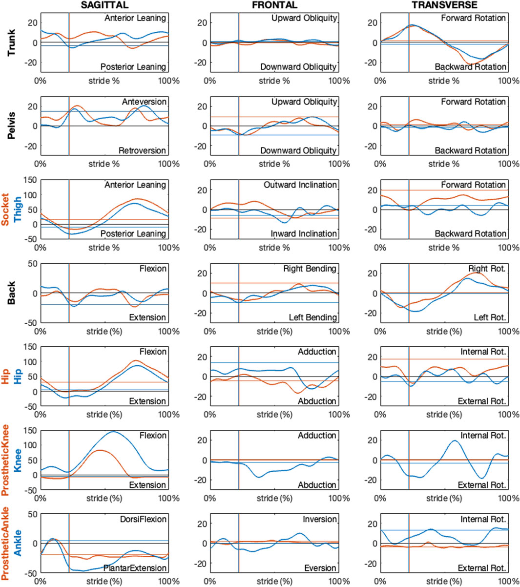
Figure 12. Sagittal, frontal and transverse absolute and relative kinematics obtained with the proposed model for a TF amputee during running. Kinematics, reported in blue for non-prosthetic (right) and in dark orange for prosthetic (left) sides, are time normalized over the stride percentage. Horizontal lines show the static kinematics. Vertical lines show the foot-off instants.
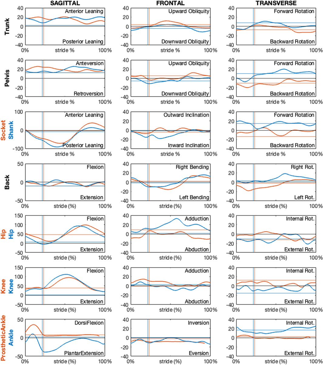
Figure 13. Sagittal, frontal and transverse absolute and relative kinematics obtained with the proposed model for a TT amputee during running. Kinematics, reported in blue for non-prosthetic (right) and in dark orange for prosthetic (left) sides, are time normalized over the stride percentage. Horizontal lines show the static kinematics. Vertical lines show the foot-off instants.
Regarding the PTFA, the running speed was 6.7 m/s. For the PTTA, the running speed was 8.7 m/s.
Kinematics obtained according to the proposed protocol correctly highlights a null prosthetic knee extension in stance and at terminal swing, as well as a null prosthetic knee abduction-adduction and internal-external rotation for the PTFA. Furthermore, the dorsal-plantar flexion of the prosthetic ankle is neutral (i.e. the same as the static asset) during late stance and swing phases, for both the PTFA and PTTA. It is worth noting that neutral dorsal-plantar flexion of the prosthetic ankle is not a null angle, even during the static trial (continuous horizontal lines in Figures 12, 13), since the distal portion of the RPF can be oriented such that its x-axis points slightly upwards or downwards with respect to the proximal segment used to define the joint. The extent to which the static plantar/dorsiflexion angles differ from zero depends on the considered RPF model. Abduction-adduction and internal-external rotation of the prosthetic ankle are neutral along the whole stride, with the deviations from the static asset possibly quantifying the vibration of the RPF.
4 Discussion
This study provides a standardized protocol for analysing the kinematics of running in PTFAs and PTTAs, while a full biomechanical analysis will be possible by integrating force plates and inertial parameters calculation for each segment. Unlike previous studies, the proposed definitions are not based on placing markers on landmarks identified on the prosthesis by their similarities with the sound limb (Kent and Franklyn-Miller, 2011). This allows the protocol to be applied to any RSP configuration, regardless of the relative position and orientation of the RSP components (i.e., sockets, adapters, pylons, prosthetic knees and prosthetic feet). The adoption of standardized local coordinate systems possibly facilitates the understanding of segmental and joint kinematics across different prosthesis configurations and studies (Sawers and Hahn, 2010), informing prosthetists and coaches in optimizing prosthesis setups for competition.
Defining one or more coordinate systems (CSs) for each prosthetic segment is crucial for both biomechanical analysis and bench/in silico testing. This paper addresses the lack of a standardised motion capture protocol for informing mechanical bench tests that can reproduce real-world conditions, and assess the functional characteristics of components specific to running (Gariboldi et al., 2025a; 2025b; 2022). Often, multiple CSs are needed for the same segment to meet different requirements. For example, in the case of transfemoral amputation, at least 3 CSs can be defined for the socket: (i) one based on the residual limb, which is considered as solid with the socket itself, (ii) one accounting for the affected hip and prosthetic knee joint, and (iii) one considering the position and orientation of the socket-clamp system. While the first is essential for defining the joint rotations of the affected hip, the second and third are necessary for correct socket alignment in a test bench environment, ensuring an accurate reproduction of in-vivo conditions in an in-vitro setting.
As previously mentioned, the definition of local reference systems follows the recommendations of the International Society of Biomechanics. The proposed CSs were developed after extensive discussions with a multi-professional group–including two prosthetists, three test engineers, and three biomechanists–and over 20 in-vivo testing sessions with multiple prosthetic configurations and socket mechanical bench testing (Gariboldi et al., 2025a; Gariboldi et al., 2025b; Gariboldi et al., 2022; Petrone et al., 2020). This approach ensures repeatability and enables a systematic investigation of the athlete-prosthesis interaction, while also promoting the integration of in-vivo biomechanics data into in-vitro (e.g., bench tests) and in silico (e.g., Finite Element Method) simulations. Such integration contributes to creating more realistic testing environments, ultimately leading to safer and more effective prosthetic designs.
One of the biggest challenges in defining the segments’ local CS is associated with the socket, which is inherently characterised by shape variability. Unlike rigid components such as screws, which are physically solid with it and universally identifiable, the socket system exhibits flexibility and variability that is needed to comfortably accommodate the residual limb, which is subject specific. This complicates consistency among measurements, therefore hindering standardization across studies but also affecting the reliability of in-vitro tests for socket mechanical characterization. The definitions given in this manuscript can be applicable on different socket shapes, as demonstrated by applying the same socket coordinate system definition to both PTFAs and PTTAs.
Another point of attention is the management of the static standing trial. It is worth noting that the transverse axis passing through the anterior iliac spine is usually not horizontal, as the prosthetic side is higher than the sound side, as part of standard RSP design practice. Depending on how the data collected during this phase of the procedure is to be used, different choices can be made. Specifically, if the static trial is intended for point calibration only, instructing the athlete to stand as still as possible within the capture volume will suffice for research purposes. However, as in the present paper, if the researcher is interested in capturing the RPF deformation during the running cycle, i.e. with the latter unloaded, one should request that the athlete stand and lean their body weight onto the sound side only. Since static kinematics reflect the athlete’s actual capabilities during the standing trial, both procedures for collecting static standing data will result in angles not being considered “neutral” for the pelvic segment and hip and knee joints. If the neutral asset is sought to help understand the actual motion around the neutral position, the standing trial should be collected with the transverse axis passing through the horizontal anterior iliac spine and the prosthetic knee fully extended. In this case, however, it is impossible to achieve an unloaded RPF. This further emphasises the idea that kinematics is highly subject-specific and difficult to normalise, and static posture subtraction should be avoided.
Although being promising, the proposed methodology requires further validation to ensure its applicability across diverse populations and prosthetic designs. The needed validation steps include establishing the reliability and reproducibility of the obtained quantities across different measurement conditions. Ideally, further studies would be necessary to assess: (i) the test-retest reliability of the protocol to ensure consistent results under the same measurement conditions; (ii) the inter-subject reliability, to evaluate how the protocol performs across athletes with different biomechanical characteristics; (iii) the inter-operator reproducibility; and, possibly, (iv) the minimal detectable changes associated with different measurement conditions. However, the limited number of high-level athletes and their heterogeneity limit the feasibility of conducting a broad validation as would be required. Addressing these limitations in future work will be crucial for advancing the protocol’s applicability. Standardization efforts and validation studies will provide a more robust foundation for the biomechanical assessment of Paralympic athletes, hopefully allowing improvement in prosthetic design and athletic performance.
Instrumental to these validation aims, to facilitate scientists worldwide to test the protocol and extend its validation, the source codes and GUI of the Olympia software for kinematic calculations, and the configuration files required to define the model for any Paralympic athlete, are published alongside the manuscript. The open access sharing of these resources aims to foster a globally validated methodology, benefiting the entire research community and contributing to the advancement of this field.
Unlike conventional motion analysis studies, this work does not propose a comparison of the obtained kinematic curves with normative data. This limitation is primarily due to this study presenting the first explicitly defined model for analysing running biomechanics in Paralympic athletes, making direct comparisons with previous methodologies challenging and formally incorrect: i.e., different models would employ distinct reference system definitions, with no directly comparable kinematics. Additionally, the running biomechanics of amputee athletes exhibit fundamental differences from those of non-amputee athletes, further restricting the applicability of normative datasets.
In conclusion, this research proposes a standardized approach to study the biomechanics of running in Paralympic athletes, providing a foundation for possibly optimizing prosthetic design, enhancing athletic performance, and fostering global collaboration to advance the field.
Data availability statement
The datasets presented in this study can be found in online repositories. The names of the repository/repositories and accession number(s) can be found in the article/Supplementary Material.
Ethics statement
The requirement of ethical approval was waived by Comitato Etico Area Vasta Emilia Centro (AVEC), which is exempt from evaluating case series. The studies were conducted in accordance with the local legislation and institutional requirements. The participants provided their written informed consent to participate in this study. Written informed consent was obtained from the individual(s) for the publication of any potentially identifiable images or data included in this article.
Author contributions
RD: Methodology, Writing – review and editing, Investigation, Writing – original draft, Software, Supervision, Data curation, Visualization, Formal Analysis, Conceptualization. SB: Formal Analysis, Conceptualization, Data curation, Methodology, Writing – review and editing, Software, Investigation, Visualization. GZ: Visualization, Data curation, Conceptualization, Formal Analysis, Writing – review and editing, Investigation, Software, Methodology. FG: Writing – review and editing, Conceptualization. MS: Conceptualization, Writing – review and editing, Visualization. GM: Writing – review and editing, Conceptualization. NP: Project administration, Resources, Conceptualization, Supervision, Methodology, Writing – review and editing. AC: Writing – review and editing, Resources, Conceptualization, Project administration, Supervision, Methodology.
Funding
The author(s) declare that financial support was received for the research and/or publication of this article. This research was supported by INAIL under the agreements n. PR19-PAI-P4 (OLYMPIA Project) and n. PR23-PAI-P3 (ProOlympia Project).
Acknowledgments
The authors express their sincere gratitude to Ambra Sabatini and Maxcel Amo Manu for their invaluable participation in the data collection and for granting permission to publish the collected data. The authors also acknowledge the technical support provided during the experimental session by Prof Giuseppe Marcolin (University of Padua), and the support in formalising the identification procedure of the socket axes provided by Maria Grazia Santi (INAIL).
Conflict of interest
The authors declare that the research was conducted in the absence of any commercial or financial relationships that could be construed as a potential conflict of interest.
Generative AI statement
The author(s) declare that no Generative AI was used in the creation of this manuscript.
Any alternative text (alt text) provided alongside figures in this article has been generated by Frontiers with the support of artificial intelligence and reasonable efforts have been made to ensure accuracy, including review by the authors wherever possible. If you identify any issues, please contact us.
Publisher’s note
All claims expressed in this article are solely those of the authors and do not necessarily represent those of their affiliated organizations, or those of the publisher, the editors and the reviewers. Any product that may be evaluated in this article, or claim that may be made by its manufacturer, is not guaranteed or endorsed by the publisher.
Supplementary material
The Supplementary Material for this article can be found online at: https://www.frontiersin.org/articles/10.3389/fbioe.2025.1655295/full#supplementary-material
References
Alcantara, R. S., Day, E. M., Hahn, M. E., and Grabowski, A. M. (2021). Sacral acceleration can predict whole-body kinetics and stride kinematics across running speeds. PeerJ 9, e11199. doi:10.7717/peerj.11199
Alcantara, R. S., Edwards, W. B., Millet, G. Y., and Grabowski, A. M. (2022). Predicting continuous ground reaction forces from accelerometers during uphill and downhill running: a recurrent neural network solution. PeerJ 10, e12752. doi:10.7717/peerj.12752
Barattini, C., Dimauro, L., Vella, A. D., and Vigliani, A. (2023). Dynamic analysis of a high-performance prosthetic leg: experimental characterisation and numerical modelling. Appl. Sci. 13, 11566. doi:10.3390/app132011566
Beck, O. N., Taboga, P., and Grabowski, A. M. (2016). Characterizing the mechanical properties of running-specific prostheses. PLoS One 11, e0168298. doi:10.1371/journal.pone.0168298
Bell, A. L., Pedersen, D. R., and Brand, R. A. (1990). A comparison of the accuracy of several hip center location prediction methods. J. Biomech. 23, 617–621. doi:10.1016/0021-9290(90)90054-7
Benedetti, M. G., Beghi, E., De Tanti, A., Cappozzo, A., Basaglia, N., Cutti, A. G., et al. (2017). SIAMOC position paper on gait analysis in clinical practice: general requirements, methods and appropriateness. Results of an Italian consensus conference. Gait Posture 58, 252–260. doi:10.1016/j.gaitpost.2017.08.003
Bouzas, S., Molina, A. J., Fernandez-Villa, T., Miller, K., Sanchez-Lastra, M. A., and Ayan, C. (2021). Effects of exercise on the physical fitness and functionality of people with amputations: systematic review and meta-analysis. Disabil. Health J. 14, 100976. doi:10.1016/j.dhjo.2020.100976
Bragaru, M., Dekker, R., Geertzen, J. H. B., and Dijkstra, P. U. (2011). Amputees and sports: a systematic review. Sports Med. 41, 721–740. doi:10.2165/11590420-000000000-00000
Breban, S. G., Bettella, F., Di Marco, R., Migliore, G. L., Cutti, A. G., and Petrone, N. (2022). “GRF analysis of two elite paralympic sprinters in steady and resisted treadmill running,” in 40th international Society of biomechanics in sports conference (Liverpool, UK), 94–97.
Cappello, A., Cappozzo, A., La Palombara, P. F., Lucchetti, L., and Leardini, A. (1997). Multiple anatomical landmark calibration for optimal bone pose estimation. 1Human Mov. Sci. 16, 259–274. doi:10.1016/s0167-9457(96)00055-3
Cappozzo, A., Della Croce, U., Leardini, A., and Chiari, L. (2005). Human movement analysis using stereophotogrammetry. Part 1: theoretical background. Gait Posture 21, 186–196. doi:10.1016/j.gaitpost.2004.01.010
Cappozzo, A., Catan, F., Crocel, D., and Leardini, A. (1995). Position an’d orientation in space of bones during movement: anatomical frame definition and determination. EINEMANN Clin. Biomech. 10, 171–178. doi:10.1016/0268-0033(95)91394-t
Cutti, A. G., Morosato, F., Gentile, C., Gariboldi, F., Hamoui, G., Santi, M. G., et al. (2023). A workflow for studying the stump–socket interface in persons with transtibial amputation through 3D thermographic mapping. Sensors 23, 5035. doi:10.3390/s23115035
Day, E. M., Alcantara, R. S., McGeehan, M. A., Grabowski, A. M., and Hahn, M. E. (2021). Low-pass filter cutoff frequency affects sacral-mounted inertial measurement unit estimations of peak vertical ground reaction force and contact time during treadmill running. J. Biomech. 119, 110323. doi:10.1016/j.jbiomech.2021.110323
Dickinson, A., Nickel, E., Fatone, S., Gariboldi, F., Steer, J., Cutti, A. G., et al. (2023). Toward standardized methods for prosthetic socket mechanical testing. Prosthet. Orthot. Int. 47, 1–2. doi:10.1097/PXR.0000000000000221
Fletcher, J. R., Gallinger, T., and Prince, F. (2021). How can biomechanics improve physical preparation and performance in paralympic athletes? A narrative review. Sports 9, 89. doi:10.3390/sports9070089
Gariboldi, F., Pasquarelli, D., and Cutti, A. G. (2022). Structural testing of lower-limb prosthetic sockets: a systematic review. Med. Eng. Phys. 99, 103742. doi:10.1016/j.medengphy.2021.103742
Gariboldi, F., Cutti, A. G., Fatone, S., Nickel, E., Dickinson, A., Steer, J., et al. (2023a). Mechanical testing of transtibial prosthetic sockets: a discussion paper from the American Orthotic and Prosthetic association socket guidance workgroup. Prosthet. Orthot. Int. 47, 3–12. doi:10.1097/PXR.0000000000000222
Gariboldi, F., Scapinello, M., Petrone, N., Migliore, G. L., Teti, G., and Cutti, A. G. (2023b). Static strength of lower-limb prosthetic sockets: an exploratory study on the influence of stratigraphy, distal adapter and lamination resin. Med. Eng. Phys. 114, 103970. doi:10.1016/j.medengphy.2023.103970
Gariboldi, F., Scapinello, M., Migliore, G. L., Cutti, A. G., and Petrone, N. (2025a). Structural evaluation of lower-limb prosthetic sockets for Running– part 1: design, implementation and first assessment of an innovative test bench. Results Eng. 26, 105224. doi:10.1016/j.rineng.2025.105224
Gariboldi, F., Scapinello, M., Migliore, G. L., Petrone, N., Teti, G., and Cutti, A. G. (2025b). Structural evaluation of lower-limb prosthetic sockets for Running– part 2: exploratory application of an innovative test bench to various socket designs. Results Eng. 26, 105279. doi:10.1016/j.rineng.2025.105279
Grood, E. S., and Suntay, W. J. (1983). A joint coordinate system for the clinical description of three-dimensional motions: application to the knee. J. Biomech. Eng. 105, 136–144. doi:10.1115/1.3138397
Hadj-Moussa, F., Ngan, C. C., and Andrysek, J. (2022). Biomechanical factors affecting individuals with lower limb amputations running using running-specific prostheses: a systematic review. Gait Posture 92, 83–95. doi:10.1016/j.gaitpost.2021.10.044
Hamner, S. R., Seth, A., and Delp, S. L. (2010). Muscle contributions to propulsion and support during running. J. Biomech. 43, 2709–2716. doi:10.1016/j.jbiomech.2010.06.025
Hansen, A. H., Childress, D. S., and Knox, E. H. (2004). Roll-over shapes of human locomotor systems: effects of walking speed. Clin. Biomech. 19, 407–414. doi:10.1016/j.clinbiomech.2003.12.001
Hobara, H., Baum, B. S., Kwon, H.-J., Miller, R. H., Ogata, T., Kim, Y. H., et al. (2013). Amputee locomotion: spring-like leg behavior and stiffness regulation using running-specific prostheses. J. Biomech. 46, 2483–2489. doi:10.1016/j.jbiomech.2013.07.009
Hobara, H., Baum, B. S., Kwon, H.-J., Linberg, A., Wolf, E. J., Miller, R. H., et al. (2014). Amputee locomotion: lower extremity loading using running-specific prostheses. Gait Posture 39, 386–390. doi:10.1016/j.gaitpost.2013.08.010
Kent, J., and Franklyn-Miller, A. (2011). Biomechanical models in the study of lower limb amputee kinematics: a review. Prosthet. Orthot. Int. 35, 124–139. doi:10.1177/0309364611407677
Kontaxis, A., Cutti, A. G., Johnson, G. R., and Veeger, H. E. (2009). A framework for the definition of standardized protocols for measuring upper-extremity kinematics. Clin. Biomech. (Bristol, Avon) 24, 246–253. doi:10.1016/j.clinbiomech.2008.12.009
Maćkała, K., Fostiak, M., and Kowalski, K. (2015). Selected determinants of acceleration in the 100m sprint. J. Hum. Kinet. 45, 135–148. doi:10.1515/hukin-2015-0014
Makimoto, A., Sano, Y., Hashizume, S., Murai, A., Kobayashi, Y., Takemura, H., et al. (2017). Ground reaction forces during sprinting in unilateral transfemoral amputees. J. Appl. Biomech. 33, 406–409. doi:10.1123/jab.2017-0008
Migliore, G. L., Petrone, N., Hobara, H., Nagahara, R., Miyashiro, K., Costa, G. F., et al. (2021). Innovative alignment of sprinting prostheses for persons with transfemoral amputation: exploratory study on a gold medal paralympic athlete. Prosthet. Orthot. Int. 45, 46–53. doi:10.1177/0309364620946910
Mistretta, P., Scapinello, M., Breban, S. G., Cutti, A. G., and Petrone, N. (2022). Instrumentation of sprint and long jump tracks of an indoor athletics field to study athletes’ performances. doi:10.5703/1288284317522
Morin, J.-B., and Sève, P. (2011). Sprint running performance: comparison between treadmill and field conditions. Eur. J. Appl. Physiol. 111, 1695–1703. doi:10.1007/s00421-010-1804-0
Murai, A., Hobara, H., Hashizume, S., Kobayashi, Y., and Tada, M. (2018). Can forward dynamics simulation with simple model estimate complex phenomena? case study on sprinting using running-specific prosthesis. ROBOMECH J. 5, 10. doi:10.1186/s40648-018-0108-8
Nagahara, R., Mizutani, M., Matsuo, A., Kanehisa, H., and Fukunaga, T. (2018). Association of sprint performance with ground reaction forces during acceleration and maximal speed phases in a single sprint. J. Appl. Biomech. 34, 104–110. doi:10.1123/jab.2016-0356
Oudenhoven, L. M., Boes, J. M., Hak, L., Faber, G. S., and Houdijk, H. (2017). Regulation of step frequency in transtibial amputee endurance athletes using a running-specific prosthesis. J. Biomech. 51, 42–48. doi:10.1016/j.jbiomech.2016.11.058
Petrone, N., Costa, G., Foscan, G., Gri, A., Mazzanti, L., Migliore, G., et al. (2020). Development of instrumented running prosthetic feet for the collection of track loads on elite athletes. Sensors Switz. 20, 5758–18. doi:10.3390/s20205758
Rigney, S. M., Simmons, A., and Kark, L. (2015). “Concurrent multibody and finite element analysis of the lower-limb during amputee running,” in 2015 37th annual international conference of the IEEE engineering in medicine and biology society (EMBC) (IEEE), 2434–2437. doi:10.1109/EMBC.2015.7318885
Sakata, H., Hashizume, S., Takemura, H., and Hobara, H. (2020). A limb-specific strategy across a range of running speeds in transfemoral amputees. Med. Sci. Sports Exerc 52, 892–899. doi:10.1249/MSS.0000000000002203
Sawers, A. B., and Hahn, M. E. (2010). The potential for error with use of inverse dynamic calculations in gait analysis of individuals with lower limb loss: a review of model selection and assumptions. JPO J. Prosthetics Orthot. 22, 56–61. doi:10.1097/JPO.0b013e3181cba08b
Taboga, P., Drees, E. K., Beck, O. N., and Grabowski, A. M. (2020). Prosthetic model, but not stiffness or height, affects maximum running velocity in athletes with unilateral transtibial amputations. Sci. Rep. 10, 1763. doi:10.1038/s41598-019-56479-8
van Oeveren, B. T., de Ruiter, C. J., Beek, P. J., and van Dieën, J. H. (2024). The biomechanics of running and running styles: a synthesis. Sports Biomech. 23, 516–554. doi:10.1080/14763141.2021.1873411
Wu, G., and Cavanagh, P. R. (1995). ISB recommendations for standardization in the reporting of kinematic data. J. Biomech. 28, 1257–1261. doi:10.1016/0021-9290(95)00017-c
Wu, G., Siegler, S., Allard, P., Kirtley, C., Leardini, A., Rosenbaum, D., et al. (2002). ISB recommendation on definitions of joint coordinate system of various joints for the reporting of human joint motion - part I: ankle, hip, and spine. J. Biomech. 35, 543–548. doi:10.1016/S0021-9290(01)00222-6
Wu, G., van der Helm, F. C., Veeger, H. E., Makhsous, M., Van Roy, P., Anglin, C., et al. (2005). ISB recommendation on definitions of joint coordinate systems of various joints for the reporting of human joint motion--Part II: shoulder, elbow, wrist and hand. J. Biomech. 38, 981–992. doi:10.1016/j.jbiomech.2004.05.042
Keywords: paralympic running, biomechanical model, lower-limb amputation, open-access software, standardized procedure
Citation: Di Marco R, Breban SG, Zullo G, Gariboldi F, Scapinello M, Migliore GL, Petrone N and Cutti AG (2025) A motion capture protocol for the kinematic analysis of transfemoral and transtibial sprinters. Front. Bioeng. Biotechnol. 13:1655295. doi: 10.3389/fbioe.2025.1655295
Received: 27 June 2025; Accepted: 10 September 2025;
Published: 04 November 2025.
Edited by:
Alessandro Ruggiero, University of Salerno, ItalyCopyright © 2025 Di Marco, Breban, Zullo, Gariboldi, Scapinello, Migliore, Petrone and Cutti. This is an open-access article distributed under the terms of the Creative Commons Attribution License (CC BY). The use, distribution or reproduction in other forums is permitted, provided the original author(s) and the copyright owner(s) are credited and that the original publication in this journal is cited, in accordance with accepted academic practice. No use, distribution or reproduction is permitted which does not comply with these terms.
*Correspondence: Roberto Di Marco, cm9iZXJ0by5kaW1hcmNvQHVuaXZyLml0, ci5kaW1hcmNvQGluYWlsLml0