Abstract
Optical interconnects are becoming a major bottleneck in scaling up future GPU racks and network switches within data centers. Although 200 Gb/s optical transceivers using PAM-4 modulation have been demonstrated, achieving higher data rates and energy efficiencies requires high-order coherent modulations like 16-QAM. Current coherent links rely on energy-intensive digital signal processing (DSP) for channel impairment compensation and carrier phase recovery (CPR), which consumes approximately 50 pJ/b, 10 times higher than future intra-data center requirements. For shorter links, simpler or DSP-free CPR methods can significantly reduce power and complexity. While Costas loops enable CPR for QPSK, they face challenges in scaling to higher-order modulations (e.g., 16/64-QAM) due to varying symbol amplitudes. In this work, we propose an optical coherent link architecture using laser forwarding and a novel DSP-free CPR system using offset-QAM modulation. The proposed analog CPR feedback loop is highly scalable, capable of supporting arbitrary offset-QAM modulations (e.g., 4, 16, 64) without requiring architectural modifications. This scalability is achieved through its phase error detection mechanism, which operates independently of the data rate and modulation type. We validated this method using GlobalFoundries monolithic 45 nm silicon photonics PDK models, with circuit- and system-level implementation at 100 GBaud in the O-band. We will investigate the feedback loop dynamics, circuit-level implementations, and phase-noise performance of the proposed CPR loop. Our method can be adopted to realize low-power QAM optical interconnects for future coherent-lite pluggable transceivers as well as co-packaged optics (CPO) applications.
1 Introduction
The rise of AI computing, driven by tens of thousands of GPUs and AI accelerators in data centers, poses significant challenges for optical interconnects and networking technologies (Naffziger, 2023; Xie and Zhang, 2022). Current state-of-the-art optical interconnects utilize pluggable transceivers operating at 112 Gb/s and 224 Gb/s PAM-4 data rates with energy efficiencies of 25 pJ/b (Nagarajan et al., 2024). Next-generation transceivers aim to achieve data rates exceeding 400 Gb/s with improved energy efficiency (Nagarajan et al., 2021). However, with limited improvements in the speed and energy efficiency of mixed-signal circuitry in advanced CMOS technologies, and fiber dispersion constraints, further increases in data rates necessitate advanced modulation schemes. While PAM-6 and PAM-8 are under investigation, their significant SNR penalties (Li et al., 2019) make them less practical. Consequently, adopting advanced coherent modulation (e.g., 16-QAM) within data centers is inevitable for achieving energy-efficient links. Although wavelength and polarization division multiplexing (WDM and PDM) can increase aggregate bandwidth per fiber, boosting data rates per wavelength/polarization remains essential to reduce the number of laser lines and improve energy efficiency.
Coherent optical communication requires precise phase and frequency alignment between the received (Rx) signal and the local oscillator (LO). Long-haul coherent transceivers, such as the 800G-ZR/ZR + standards (Zhou et al., 2023), employ power-intensive digital signal processing (DSP) to handle channel impairments such as chromatic dispersion (CD), differential group delay (DGD), and carrier phase recovery (CPR) (Nagarajan et al., 2024; Ip et al., 2008). These DSP methods require oversampling ADCs, resulting in energy consumption around 50 pJ/b and increased system complexity. In short-reach interconnects (e.g., inter-rack links 1 km), many DSP functionalities—such as dispersion compensation—are unnecessary and can be eliminated (Saleh et al., 2021). However, frequency and phase recovery remain essential. Therefore, performing CPR in analog front-end can eliminate or significantly simplify DSP, realizing the power efficiency requirements of data centers.
Previous studies have demonstrated DSP-free CPR systems for QPSK/4-QAM modulations (Valenzuela et al., 2022; Movaghar et al., 2023; Ashok et al., 2021b; Ashok et al., 2021a) using Costas loops (Chul Park et al., 2012; Dick et al., 2000). These systems utilize optical phase-locked loops (OPLLs) (Valenzuela et al., 2022), optical delay-locked loops (ODLLs) (Movaghar et al., 2023), and traditional PLLs (Ashok et al., 2021b) for phase and frequency mismatches in laser-forwarded links. However, as modulation schemes scale to higher orders (e.g., 16/64/256-QAM), Costas loops fail to correct phase errors due to varying symbol amplitudes (Rezaei et al., 2024).
For instance, using unmodified Costas loops for 16-QAM introduces symbol-dependent phase error detection, creating false I/Q locking points that deviate from (Patil et al., 2016). A proposed solution involves sub-sampling the 16-QAM signal to form a 4-QAM constellation (Mizutori et al., 2017), but this relies on accurate symbol detection during CPR, which is impractical. Furthermore, sub-sampling reduces CPR loop bandwidth.
Another work (Liu et al., 2024) employed the pilot tone concept by adding a low-frequency test tone to the transmitted optical signal. At the receiver, phase error is detected and compensated based on the power of this tone. However, even after compensation, this low-power tone remains in the signal, interfering with the data and causing periodic jitter, ultimately impacting BER.
In this work, we propose a DSP-free carrier phase recovery system optimized for offset-QAM modulation. Offset-QAM is generated by leaking a portion of the LO signal into the modulated QAM signal at the transmitter, as shown in Figure 1. This can be achieved using Mach-Zehnder Modulators (MZMs) operating with an offset from the transmission null (Lu et al., 2010), or, as recently demonstrated, by employing micro-ring modulators (MRMs) (Sturm and Moazeni, 2024). In offset-QAM, the phase offset between the Rx signal and LO paths is detected based on the average power/voltage difference between the in-phase (I) and quadrature (Q) signals. This difference serves as an error signal to correct the phase error using a phase shifter (PS) in the LO path for laser-forwarded links. The laser-forwarding technique (Mehta et al., 2020) forwards a portion of the transmitter (Tx) laser to the receiver to serve as the LO, maintaining zero frequency mismatch, eliminating the need for an additional LO laser, and mitigating laser phase noise (PN). This approach reduces cost and enhances reliability. The proposed CPR system supports any offset-QAM modulation level (e.g., 4, 16, 256) without architectural modifications, making it highly scalable for future high-order modulations. Unlike Costas loops, our method avoids the need for high-speed analog devices (e.g., mixers, XORs) and does not suffer from phase ambiguity (Xiao and Cheng, 2006; Sadchenko and Kushnirenko, 2018).
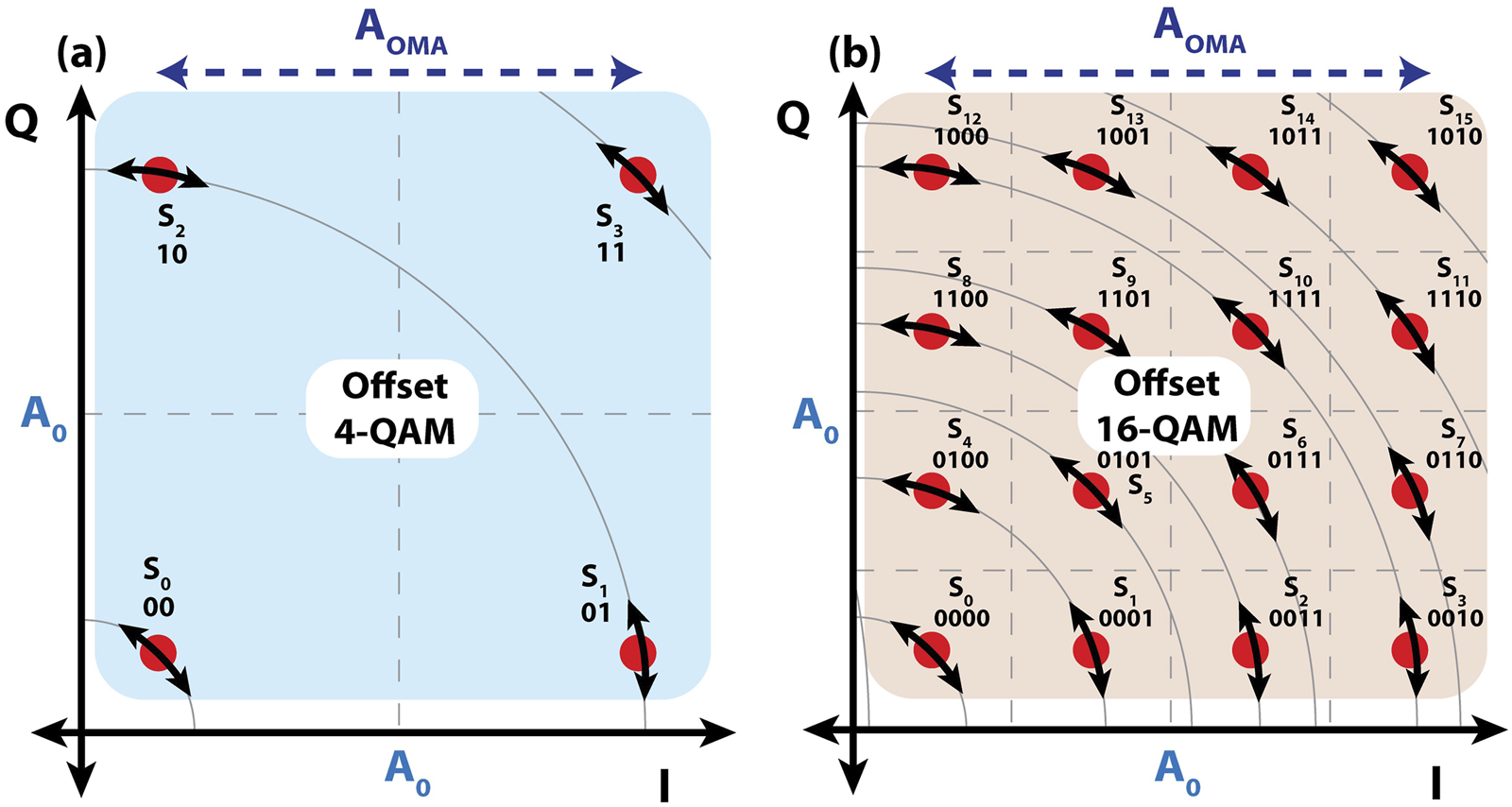
FIGURE 1
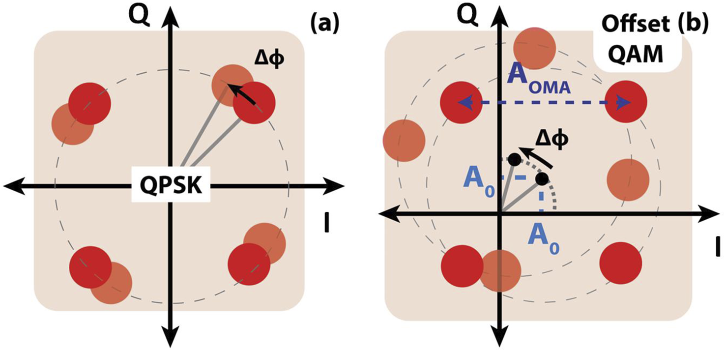
The constellation of (a) 4-QAM (QPSK) (b) 4-offset-QAM modulation with and without the phase error between the Rx signal and LO paths. The offset-QAM format introduces an intentional offset affecting the constellation rotation in presence of phase error.
The proposed receiver is modeled and simulated using GlobalFoundries (GF) 45 nm monolithic silicon photonics (GF45SPCLO) (Rakowski et al., 2020) PDK models, with circuit/system-level implementation at 100 GBaud. This approach paves the way for low-power QAM interconnects in future co-packaged optics (CPO) and coherent-lite (Lam et al., 2021) applications, enabling energy-efficient data rates exceeding 400 Gb/s per channel.
The paper is organized as follows: Section 2 introduces our DSP-free CPR techniques for offset-QAM modulation. Section 3 analyzes loop dynamics, including stability and laser phase noise. Section 4 discusses the circuit implementation. Section 5 presents simulation results and trade-offs. Finally, Section 6 concludes the paper.
2 Proposed DSP-Free carrier phase recovery
Optical coherent communication relies on precise frequency and phase locking between the received signal and the local oscillator. Any phase error between these paths induces I/Q cross-talk, severely impacting symbol/bit error rates (SER and BER) (Chang et al., 2009). Figure 1 presents the constellation diagrams for QPSK/4-QAM and 4-offset-QAM, highlighting the effects of phase offset between the Rx and LO signals. In QPSK/4-QAM, a phase offset causes the entire constellation to rotate, which can be corrected using the Costas loop technique (Movaghar et al., 2023; Valenzuela et al., 2022; Ashok et al., 2021b). However, in offset-QAM, phase offset rotates the constellation center and distorts amplitudes with respect to the origin making the Costas loop approach ineffective (Rezaei et al., 2024). We have proposed a novel technique to detect the phase offset between the Rx signal and LO paths based on the average power or voltage difference between the in-phase (I) and quadrature (Q) signals in offset-QAM modulation. Figure 2a illustrates the CPR block diagram for laser-forwarded links using a tunable phase shifter in the LO path. In this approach, the Tx laser output is split, with one portion modulated with data and the other transmitted to the Rx as the LO signal. The phase error between the Rx and LO signals is detected in the CPR block and then compensated using a phase shifter in the LO path. Two techniques for phase error detection are shown in Figures 2b,c. The I and Q signals, before phase error compensation, are modeled in Equation 1:where is a constant due to offset-QAM modulation and and are . Then high-frequency portions of and are filtered using low-pass filters, retaining the average voltage as shown in Equation 2:
FIGURE 2
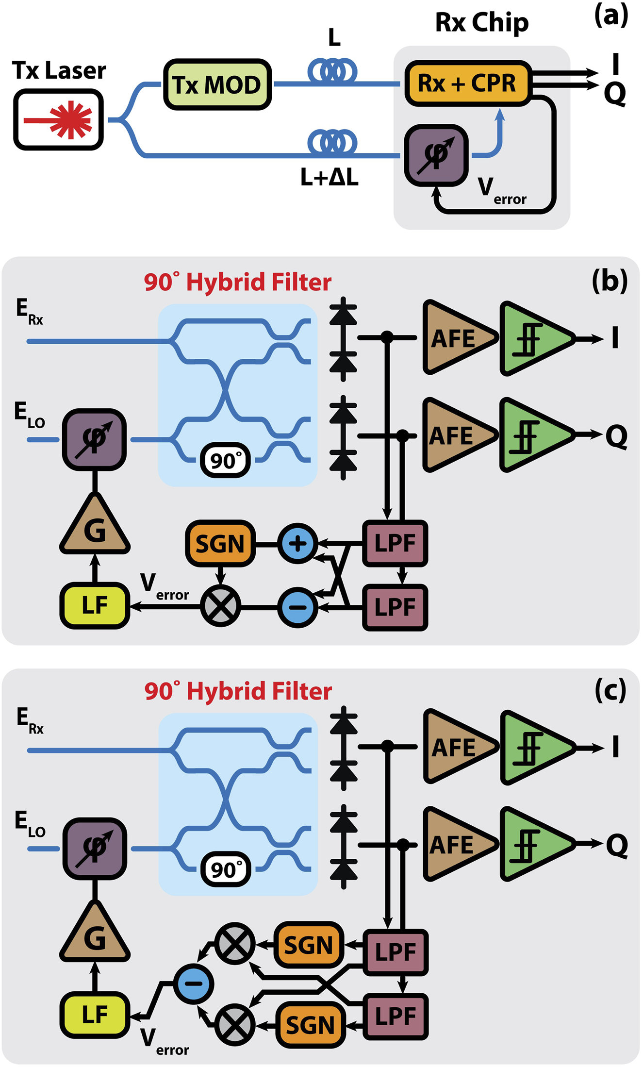
(a) Block diagrams of the proposed offset-QAM coherent receiver using (b) Method 1 and (c) Method 2 for LO phase recovery.
In Method 1, the outputs of the low-pass filters in the I and Q paths are subtracted, generating an error signal equal to . However, if the error signal is in the region where the slope is positive, the loop becomes unstable. To maintain stability, the summation of and is used as a select signal to choose between and - in different regions. For example, when , and the error signal’s slope is positive, is positive and chooses , and vice versa. This ensures that the error signal matches what is depicted in Figure 3.
FIGURE 3
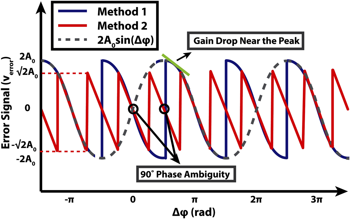
The error signal generated by Method 1 and Method 2.
In Method 2, and are sent to limiting amplifiers (SGN) and mixers, then subtracted, similar to the Costas loop technique, producing an error signal shown in Figure 3 (Movaghar et al., 2023). This method generates a sawtooth error signal that maintains constant gain over the entire range. However, the periodicity of introduces phase ambiguity between the I and Q signals at the receiver (Ashok et al., 2021b; Ashok et al., 2021a). To resolve this, differential coding during modulation and demodulation is required.
While Method 1 avoids the phase ambiguity, its gain diminishes near the peaks, affecting the loop bandwidth and phase error compensation time. In this work, we adopt the phase detection technique based on Method 1.
3 CPR loop dynamics
In this section, the CPR loop dynamics are analyzed in terms of stability, bandwidth, residual phase error, and phase noise performance.
In the transmitter, the electric field of the laser source can be expressed in Equation 3:where , , , and denote the laser’s electric field magnitude, center frequency, initial phase, and phase noise, respectively. This signal is subsequently modulated with offset-QAM data and transmitted over fiber. At the receiver, the Rx signal beats with the LO signal which is a portion of the Tx laser forwarded to the receiver and generates a beat signal proportional to . Assuming a length mismatch of between the Rx signal and LO paths, the beat signal at the receiver has a phase noise expressed as ; where , with being the refractive index and the speed of light (Zhou et al., 2021). Figure 4a illustrates the receiver’s phase linear model, where . In this context, denotes the modulation phase, refers to the phase offset caused by the length mismatch between the Rx signal and LO paths, is the phase error detected by the CPR loop, and represents the open-loop transfer function of the CPR.
FIGURE 4
(a) The linear small-signal phase modeling of the CPR system (b) the simplified phase model after averaging.
Since is initially filtered by low-pass filters, the loop model simplifies to the form shown in Figure 4b, where . The linearized open-loop transfer function is expressed in Equation 4:where is the phase error detector gain expressed as , with indicating the average photocurrent of the I/Q signals, defined as . Here, and correspond to the magnitudes of the electric field for the LO and the average I and Q signals, respectively. For DC-balanced I/Q data streams, equals as shown in Figure 1. The photodiode responsivity is represented by and is the current to voltage conversion gain. It is important to note that in Method 1, is not constant and exhibits variations near the peak; however, for simplicity, it is approximated by its value in the linear region. refers to the gain of the phase shifter driver and , , and represent the gain, zero, and pole of the loop filter, respectively, while and denote the gain and electrical 3-dB bandwidth of the phase shifter.
Figure 5 presents the Bode plot of the proposed CPR system, with parameters specified in Table 1. The system demonstrates a phase margin of , a crossover frequency of 160 kHz, and a closed-loop bandwidth of 216 kHz.
FIGURE 5
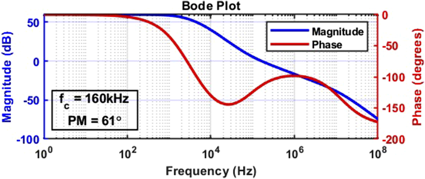
Magnitude and phase plots of the open-loop transfer function of the CPR system.
TABLE 1
| 2.55e-2 (V/rad) | 1.2e3 (V/V) | 2 (V/V) |
| 15.7 (rad/V) | 80 kHz | 6 kHz |
| fPS | ||
| 2 kHz | ||
CPR loop parameters.
3.1 Residual phase error
The residual phase error can be determined from the phase error transfer function, given by . The static phase error, resulting from a constant input phase offset of , can be calculated from in Equation 5:
Replacing the parameters in 5 with the values given in Table 1 results in the static phase error equal to for (the calculated loop gain is based on the linear approximation of ). For instance, with , the resulting phase error is approximately . The residual phase error can be further minimized by increasing the loop gain.
3.2 Laser phase noise
The phase noise of a Lorentzian-shaped laser linewidth can be described as a random walk Wiener process with a power spectral density (PSD) of (Zhou et al., 2021) in frequency domain, where is the laser linewidth. To accurately calculate the variance of the resulting Gaussian phase noise, we need to take into account the effect of the CPR loop. Taking the Fourier transform of the detected signal phase noise, we obtain Equation 6:where and are the phase noises of the beating signal and original laser in the frequency domain, and is the CPR open-loop transfer function as mentioned before. Therefore, the power spectral densities are related by Equation 7:
The total phase noise power can be calculated from Equation 8:
Figure 6 shows the PSD of the beat signal’s phase noise for different CPR loop bandwidths. In this figure, the laser-forwarding technique shapes the laser phase noise depending on as shown in Equation 7. The term exhibits high-pass behavior so the CPR loop bandwidth further filters the phase noise up to its cutoff. Increasing the CPR loop bandwidth reduces the phase noise power more effectively.
FIGURE 6
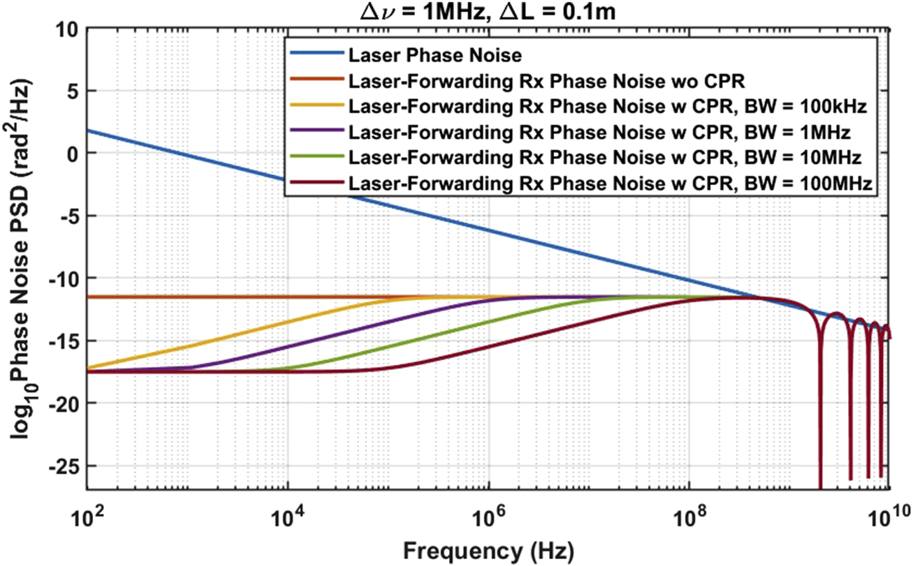
Effect of laser forwarding technique and CPR loop bandwidth on the PSD of the beat signal phase noise ( and denote laser linewidth and forwarding path mismatch length, respectively).
As mentioned before, the phase noise of the beat signal can be represented as Gaussian noise with a mean of 0 and variance of . With this, we can calculate the theoretical BER with respect to the signal-to-noise ratio (SNR) and laser phase noise.
3.2.1 Impact of laser phase noise on BER in 4-offset-QAM
Figure 7a illustrates the constellation diagram of 4-Offset-QAM, where symbols rotate on circles with radius proportional to their symbol magnitude. The symbol error rate and bit error rate are in Equation 9 (Zhou et al., 2021):where is the modulation depth (equal to 4 for 4-offset-QAM), is the probability of symbol occurring (equal to 0.25 for 4-offset-QAM), and is the conditional probability that the transmitted symbol is incorrectly detected as one of the other symbols by the receiver. occurs when either the I or Q terms, or both, are incorrectly detected and can be calculated from Equation 10 (Zhou et al., 2021):where and represent the probability of incorrectly decoding the I-component and Q-component, respectively, resulting in an error detecting . Offset-QAM exhibits a different BER expression compared to QPSK, attributed to its offset value. Recalling from Equation 1, we can simplify I and Q equations to the format shown in Equation 11:where is the offset-QAM offset, and are , is the beat signal phase noise, is the input-referred noise at the AFE input, consisting of AFE and CPR thermal noise as well as PD shot noise, represented as , and modeled as white Gaussian noise with a PSD of . Next, we show the conditional error probability for the symbol, and the same calculation method applies to the remaining symbols. The error in detecting the symbol occurs when the combined effects of noise and phase noise causes to fall below and/or to exceed . The conditional error probability for the symbol is given in Equation 12:
FIGURE 7
Effect of laser phase noise on (a) 4-offset-QAM and (b) 16-offset-QAM constellations.
As seen in this equation, depending on where the location of the center is, the phase noise effect on BER varies. As the center moves closer to the origin, phase noise performance improves. Assuming , we can simplify the aforementioned equation into Equation 13:where erfc(.) is the complementary error function defined in Equation 14:
The total conditional error probability due to the phase noise can be calculated from Equation 15 (Zhou et al., 2021):where is the PDF of the beat signal Gaussian phase noise with the variance calculated above . Similarly, we can calculate .
With and calculated, we can determine and subsequently the error probability of the other symbols, as well as the SER and BER from Equation 9. To have a universal comparison of BER versus SNR, the SNR is defined as the ratio of the average energy per symbol to the noise power spectral density, denoted by . The average symbol energy can be calculated from Equation 16:
For 4-offset-QAM, we have . To investigate the impact of the offset-QAM center location , we calculated the BER versus SNR for various values of . To evaluate BER performance, we have compared all results with a KP4 forward error correction (FEC) standard which requires a BER threshold of (Chagnon et al., 2016). In practice, any other FEC standard can be chosen depending on the link latency and application-level specifications. To perform a fair comparison between QAM and offset-QAM modulation, it is essential to account for the effect of the offset on the amplitude noise, . In offset-QAM, the offset introduces a DC component at the photodetector output, which leads to increased PD shot noise. For state-of-the-art 100Gbaud links, the analog front-end noise is approximately (Zhou, 2025). Assuming an OMA of at the PD output (to match with simulation results provided in Section 5), the offset is , which results in an rms shot noise of . Since the contribution of carrier phase recovery (CPR) noise is negligible compared to AFE noise and PD shot noise, the total power spectral density of the amplitude noise, , can be expressed as . The results in Figure 8 show that for small offsets, the BER performance of conventional 4-QAM and 4-offset-QAM is nearly identical. It is worth mentioning that, for the worst-case scenario, , the SNR penalty between QAM and offset-QAM is .
FIGURE 8
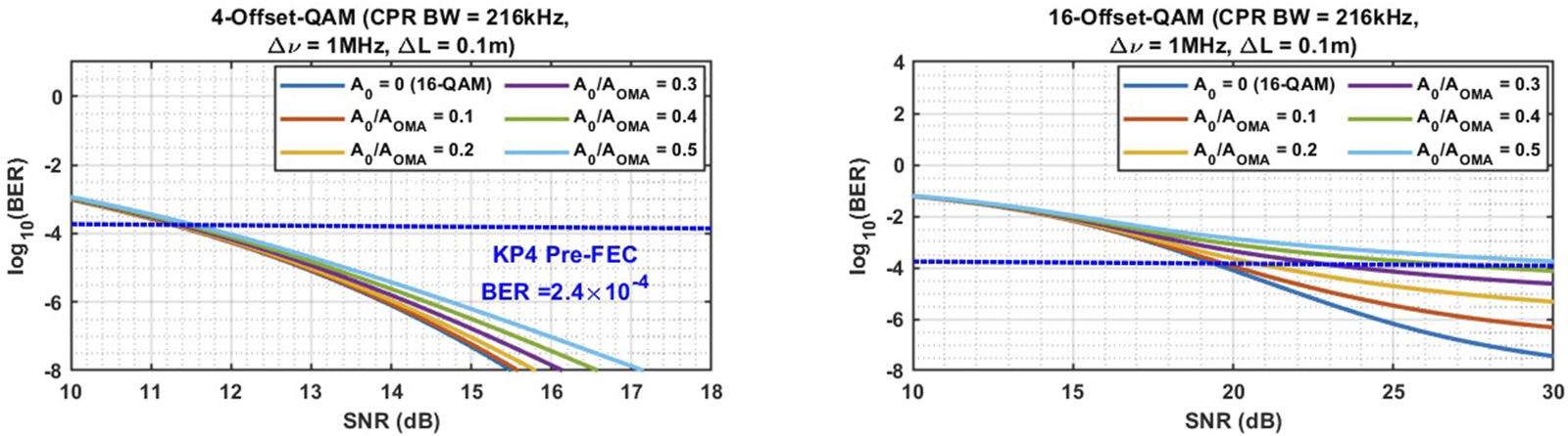
Theoretical BER vs. SNR for 4- and 16-Offset-QAM for various offset-to-OMA ratio values. Dashed lines indicate the FEC limits of for KP4 FEC.
Next, we examine the effect of the CPR loop bandwidth on the BER by calculating the BER versus the SNR for different loop bandwidth values for . As depicted in Figure 9, the effect of loop bandwidth on BER for 4-offset-QAM is negligible.
FIGURE 9
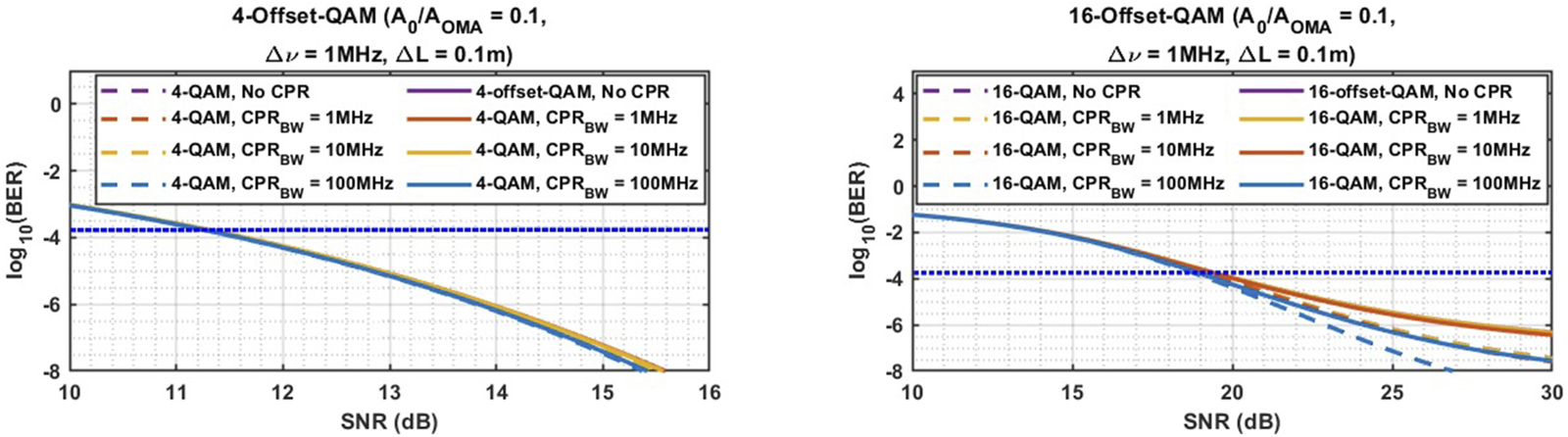
Theoretical BER vs. SNR for 4- and 16-Offset-QAM for different CPR loop bandwidths.
We also studied the impact of laser linewidth on BER. DFB lasers typically exhibit linewidths in the range of 1–10 MHz (Zhou et al., 2021). As shown in Figure 10, as the linewidth increases from 100 kHz to 1 MHz, the required SNR penalty to achieve a BER of is approximately 0.2 dB.
FIGURE 10
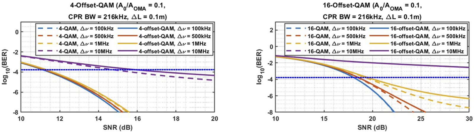
Theoretical BER vs. SNR for 4- and 16-Offset-QAM for various laser linewidths.
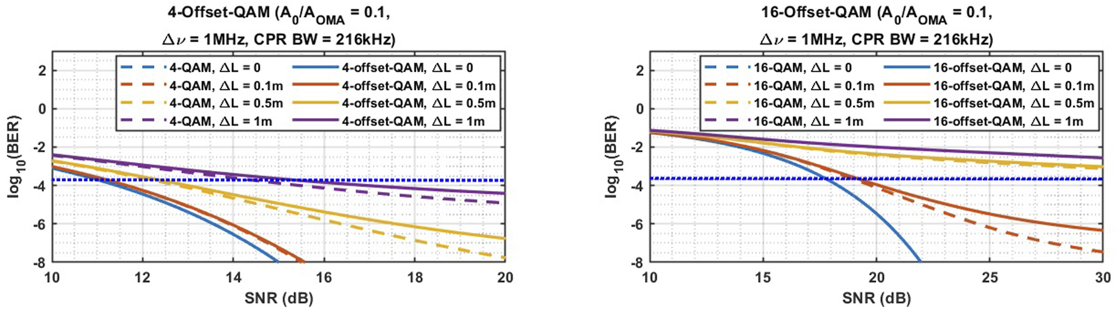
Furthermore, we investigated the effect of length mismatch on BER. As illustrated in Figure 11, for a laser linewidth of 1 MHz, when the length mismatch exceeds 50 cm, the BER drops significantly. This highlights the importance of carefully managing the splitting of the laser output between the transmitter and local oscillator LO to ensure that the length mismatch remains within a few centimeters.
FIGURE 11
Theoretical BER vs. SNR for 4- and 16-Offset-QAM for various LO/Rx signal fiber length mismatch.
3.2.2 Effect of laser phase noise on BER for 16-offset-QAM
Next, we investigate the effect of laser phase noise on BER for 16-offset-QAM modulation, using a procedure analogous to that for 4-offset-QAM. Figure 7b presents the constellation diagram of 16-Offset-QAM, illustrating the symbol shifts caused by phase noise. The values of I and Q fall within the set , with the center located at (, ). The SER can be calculated using Equation 9, setting to 16 and to 0.0625. The conditional error probability of the symbols can then be calculated from Equation 10. Here, we demonstrate the calculation of the conditional error probability for the symbol (, ). The error in detecting the symbol occurs when the combined effects of noise and phase noise cause to fall below or exceed , and/or to exceed . Assuming , the conditional error probability for the symbol can be calculated from Equations 17, 18:
Similarly, we can determine the conditional error probability for the remaining symbols to calculate the total SER, and therefore, the BER. From Equation 16, we have . The results shown in Figure 8 indicate that for a small offset , the BER performance of regular 16-QAM and 16-offset-QAM are nearly identical. However, as the offset increases, such as when , significant SNR penalties are observed. To provide reasonable input range for the CPR system and minimize the SNR penalty for 16-offset-QAM, is chosen.
As shown in Figure 9, for a BER of with a linewidth of 1 MHz and a length mismatch of 10 cm, a CPR bandwidth of 10 MHz and below has about 1 dB SNR penalty compared to the 100 MHz bandwidth. As demonstrated in Figure 10, increasing the linewidth from 100 kHz to 1 MHz results in 2 dB SNR penalty. Finally, as depicted in Figure 11, for a DFB laser with a linewidth of 1 MHz, a length mismatch of 10 cm results in SNR penalty of 1 dB compared to the case with no length mismatch and, consequently, no phase noise. These findings highlight the critical importance of selecting the offset-QAM center location and DFB laser linewidth, as well as designing the system to minimize the length mismatch between the LO and Rx signal paths. It is important to note that we have control over the length mismatch, which can be adjusted by tuning the fiber length to significantly reduce the SNR penalty.
4 Coherent receiver circuit implementation
4.1 Offset-QAM transmitter modeling
The 4-offset-QAM transmitter was modeled using ideal spectre models supporting up to to primarily evaluate the performance of the proposed CPR system at high baud rates. Additionally, the transmitter was extended to support 16-offset-QAM to assess the effectiveness of the proposed CPR system for higher-order offset-QAM modulation formats.
4.2 Circuit implementation of offset-QAM CPR system
Figure 12 shows the block diagram of the coherent receiver that can be used for any levels of offset-QAM modulation. A detailed circuit implementation of the coherent receiver is provided below.
FIGURE 12
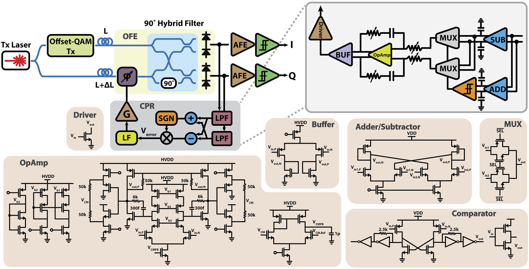
The circuit-level block diagram of the proposed Offset-QAM receiver.
4.2.1 Optical front-end (OFE)
The local laser is forwarded from the transmitter side through an ideal fiber (channel impairments have not been included). A thermal phase shifter with a 2 kHz bandwidth in the LO path is used to adjust the LO phase via the CPR loop. At the receiver, the Rx and LO signals beat together in a optical hybrid filter, followed by the photodetectors (PDs) with 50 GHz bandwidth that decode the differential I and Q signals. All optical components utilized in the OFE are actual PDK components, enabling accurate system-level performance evaluation.
4.2.2 Carrier phase recovery system
In the carrier phase recovery block, the I and Q differential outputs are differenced in current mode using a subtractor, followed by a capacitor for initial high-speed data filtering, generating an error signal proportional to . The error signal is then processed by an adder and a comparator, which select only the negative slope to ensure loop stability. The comparator is implemented using a non-clocked strong-arm latch comparator followed by inverters, with the first stage setting the bias point of the comparator.
To extract the average of the I and Q difference, a low-pass filter with a very low cutoff frequency is required. This is achieved using an active loop filter with high DC gain to guarantee zero remaining phase error between the LO and Rx signals. The loop filter consists of a differential operational amplifier (OpAmp) with gain and capacitive feedback in series with a resistive-DAC, creating a variable zero that enhances both bandwidth and loop stability. The OpAmp architecture is shown in Figure 12. The first stage is a telescopic design with common-mode feedback, while the second stage is a common-source amplifier with resistive feedback. The driver is a single transistor that continuously adjusts the LO phase shifter’s phase until the loop locks and the phase offset is zero. The VDD and HVDD are 1 V and 1.8 V, respectively. provides a swing range of 250 mV to 1.8 V that can compensate for approximately phase offset between the Rx and LO signals.
5 Simulation results
We have designed and simulated the proposed laser-forwarded carrier phase recovery system using GlobalFoundries monolithic 45 nm silicon photonics PDK models in Cadence. The parameter values used in this design are listed in Table 1. The baud rate is , corresponding to data rates of for 4-offset-QAM and for 16-offset-QAM. Eye diagrams artifacts are mainly due to the bandwidth limitations of the photodetectors ( with a capacitance) which can be improved using equalization techniques. The laser has a linewidth of , and there is a length mismatch between the Rx signal and LO paths. The CPR loop bandwidth is . In these simulations, and are set to and , and the AFE first stage is modeled as a resistor.
To evaluate the functionality of the design, we performed closed-loop simulations for a phase offset of between the Rx and LO signals which is applied by an extra phase shifter in the LO path. Figure 13A shows the eye diagram of I and Q signals for 4-offset-QAM at the PDs output (input of the AFE) under three different scenarios: without the CPR loop, with the CPR loop and no phase noise, and with the CPR loop in the presence of phase noise. It is worth mentioning that, to clearly observe the effect of laser phase noise on the eye diagrams, laser phase noise is the only noise source included in the simulation setup. As can be seen in this figure, the CPR loop is able to cancel the phase offset with less than residual phase error. However, in the presence of phase noise, the eye opening is reduced.
FIGURE 13
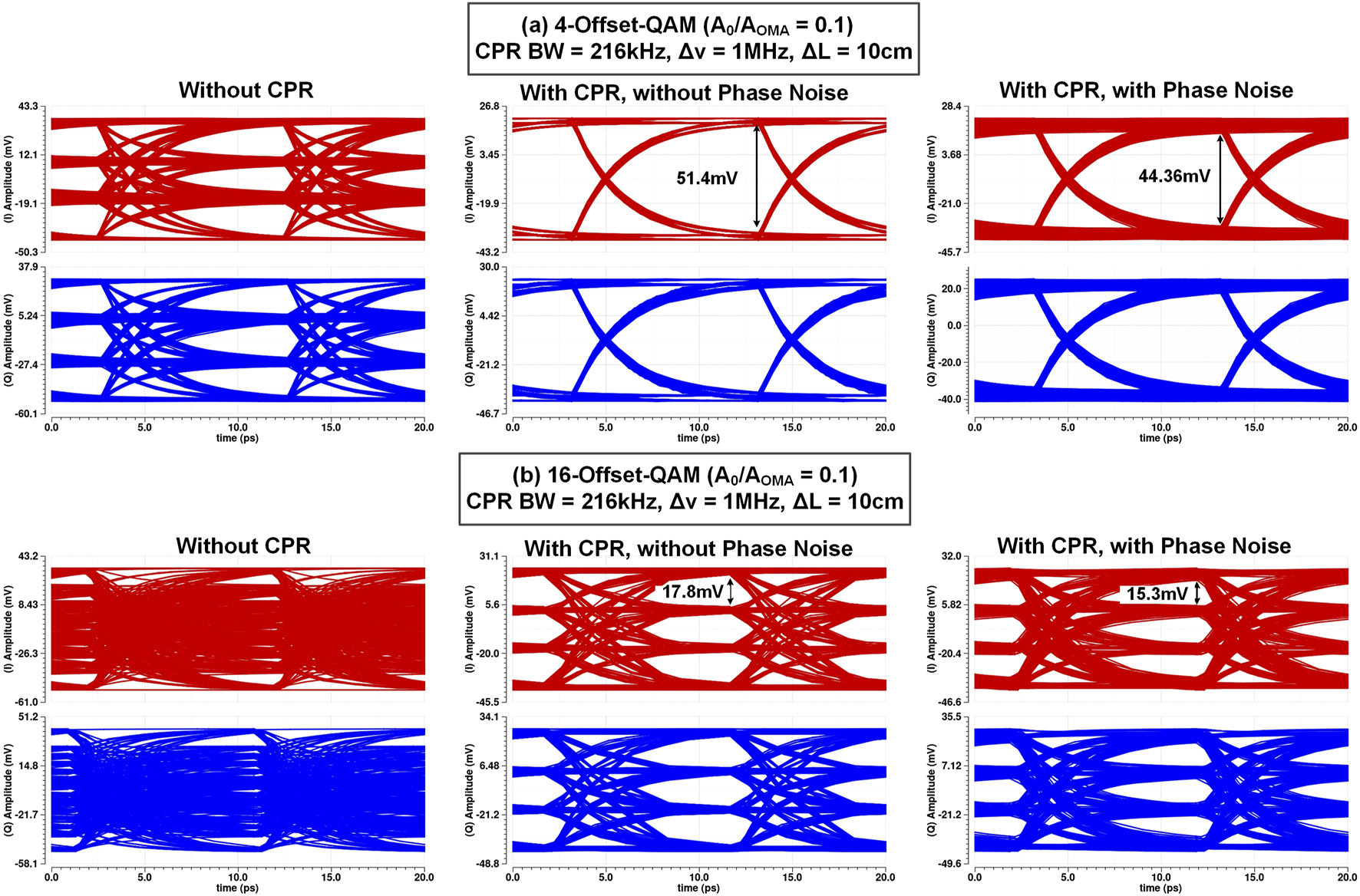
Simulated eye-diagrams of the I and Q channels at the AFE input nodes, for a 100 GBaud offset-QAM receiver with an example phase offset of between signal and LO paths at: (a) 200 Gb/s for 4-offset-QAM (b) 400 Gb/s for 16-offset-QAM with offset-to-OMA ratio equal to 0.1, carrier phase recovery loop bandwidth of 216 kHz, laser linewidth of 1 MHz and signal/LO path length mismatch of 10 cm.
Figure 13b presents the results for for 16-offset-QAM. As seen in the figure, the proposed architecture successfully cancels the phase offset for 16-offset-QAM without requiring any changes to the design.
In the presence of phase noise, to achieve the same performance as in the absence of phase noise, we must reduce the phase noise power. This can be achieved by using a laser with a narrower linewidth, minimizing the length mismatch between the Rx signal and LO paths, or increasing the effective CPR closed-loop bandwidth, which is mainly limited by the thermal phase shifter bandwidth in this process.
6 Conclusion
We have proposed, modeled, and simulated a DSP-free offset-QAM coherent receiver architecture that can perform CPR for any offset-QAM modulation level (e.g., 4, 16, 64) without architectural adjustments that can solve the scalability problem of previously proposed DSP-free CPR systems for QAM modulation. Combined with laser-forwarding, we believe this method can become a solution for future low power coherent links inside data centers. We used electro-optical spectre models in Cadence using the GF45SPCLO for simulation. Received eye-diagram operating at a baud rate of 100Gbaud at the PD outputs are measured for both 4- and 16-offset-QAM. Additionally, we studied the effects of laser linewidths, LO/Rx signal fiber length mismatch, and CPR loop bandwidth on BER. We have also elaborated on the circuit block implementation of key loop components.
Realistic link scenarios assuming 1 MHz laser linewidth and fiber length mismatch show that a 400 Gb/s 16-Offset-QAM link with an SNR of can meet the KP4 FEC requirements. Our proposed approach can become a solution to realize DSP-free linear coherent optical transceivers (both pluggables and CPO) for 400 Gb/s links and beyond.
Statements
Data availability statement
The original contributions presented in the study are included in the article/supplementary material, further inquiries can be directed to the corresponding author.
Author contributions
MR: Investigation, Software, Writing – review and editing, Resources, Writing – original draft, Methodology, Data curation, Formal Analysis, Validation, Visualization. DS: Methodology, Writing – review and editing. PZ: Methodology, Writing – review and editing. SM: Project administration, Conceptualization, Writing – review and editing, Supervision, Funding acquisition.
Funding
The author(s) declare that financial support was received for the research and/or publication of this article. This work is supported by NSF CAREER (ECCS- 2142996), NSF ENG-SEMICON (ECCS-2430776) and SRC PKG Programs. The authors would like to thank GlobalFoundries for providing silicon fabrication and PDK through the 45SPCLO university partnership program.
Conflict of interest
The authors declare that the research was conducted in the absence of any commercial or financial relationships that could be construed as a potential conflict of interest.
Generative AI statement
The author(s) declare that no Generative AI was used in the creation of this manuscript.
Any alternative text (alt text) provided alongside figures in this article has been generated by Frontiers with the support of artificial intelligence and reasonable efforts have been made to ensure accuracy, including review by the authors wherever possible. If you identify any issues, please contact us.
Publisher’s note
All claims expressed in this article are solely those of the authors and do not necessarily represent those of their affiliated organizations, or those of the publisher, the editors and the reviewers. Any product that may be evaluated in this article, or claim that may be made by its manufacturer, is not guaranteed or endorsed by the publisher.
References
1
Ashok R. Naaz S. Kamran R. Gupta S. (2021a). Analog domain carrier phase synchronization in coherent homodyne data center interconnects. J. Light. Technol.39, 6204–6214. 10.1109/jlt.2021.3096605
2
Ashok R. Nambath N. Gupta S. (2021b). Carrier phase recovery and compensation in analog signal processing based coherent receivers. J. Light. Technol.40, 2341–2347. 10.1109/jlt.2021.3135857
3
Chagnon M. Lessard S. Plant D. V. (2016). 336 Gb/s in direct detection below KP4 FEC threshold for intra data center applications. IEEE Photonics Technol. Lett.28, 2233–2236. 10.1109/LPT.2016.2590983
4
Chang S. H. Chung H. S. Kim K. (2009). Impact of quadrature imbalance in optical coherent qpsk receiver. IEEE Photonics Technol. Lett.21, 709–711. 10.1109/LPT.2009.2016759
5
Chul Park H. Lu M. Bloch E. Reed T. Griffith Z. Johansson L. et al (2012). 40Gbit/s coherent optical receiver using a Costas loop. Opt. Express20, B197–B203. 10.1364/OE.20.00B197
6
Dick C. Harris F. Rice M. (2000). “Synchronization in software radios. Carrier and timing recovery using FPGAs,” in Proceedings 2000 IEEE symposium on field-programmable custom computing machines (cat. No.PR00871), 195–204. 10.1109/FPGA.2000.903406
7
Ip E. Lau A. P. T. Barros D. J. F. Kahn J. M. (2008). Coherent detection in optical fiber systems. Opt. Express16, 753–791. 10.1364/OE.16.000753
8
Lam C. F. Zhou X. Liu H. (2021). Coherent-lite for beyond 400GbE. IEEE802 (3).
9
Li F. Li Z. Sui Q. Li J. Yi X. Li L. et al (2019). “200 Gbit/s (68.25 gbaud) PAM8 signal transmission and reception for intra-data center interconnect,” in Optical fiber communication conference (OFC) 2019 (Optica Publishing Group). W4I.3. 10.1364/OFC.2019.W4I.3
10
Liu L. Xue B. Yuan P. Lu W. Fang Y. Liu Z. et al (2024). Dsp-free coherent detection for short-reach frequency-synchronous optical networks. J. Light. Technol.42, 5128–5133. 10.1109/jlt.2024.3386700
11
Lu G.-W. Sköld M. Johannisson P. Zhao J. Sjödin M. Sunnerud H. et al (2010). 40-Gbaud 16-QAM transmitter using tandem IQ modulators with binary driving electronic signals. Opt. Express18, 23062–23069. 10.1364/OE.18.023062
12
Mehta N. Lin S. Yin B. Moazeni S. Stojanović V. (2020). A laser-forwarded coherent transceiver in 45-nm SOI CMOS using monolithic microring resonators. IEEE J. Solid-State Circuits55, 1096–1107. 10.1109/JSSC.2020.2968764
13
Mizutori A. Abe T. Kodama T. Koga M. (2017). “Optical 16-qam signal homodyne detection by extracting+/-π/4 and+/-3π/4-phase symbols,” in 2017 optical fiber communications conference and exhibition (OFC) (IEEE), 1–3.
14
Movaghar G. Arrunategui V. Liu J. Maharry A. Schow C. Buckwalter J. (2023). “A 112-gbps, 0.73-pJ/bit fully-integrated O-band IQ optical receiver in a 45-nm CMOS SOI-photonic process,” in 2023 IEEE radio frequency integrated circuits symposium (RFIC) (IEEE), 5–8.
15
Naffziger S. (2023). “Innovations for energy efficient generative AI,” in 2023 international electron devices meeting (IEDM), 1–4. 10.1109/IEDM45741.2023.10413684
16
Nagarajan R. Lyubomirsky I. Agazzi O. (2021). Low power dsp-based transceivers for data center optical fiber communications (invited tutorial). J. Light. Technol.39, 5221–5231. 10.1109/JLT.2021.3089901
17
Nagarajan R. Martino A. Morero D. A. Patra L. Lutkemeyer C. Castrillón M. A. (2024). Recent advances in low-power digital signal processing technologies for data center applications. J. Light. Technol.42, 4222–4232. 10.1109/JLT.2024.3399032
18
Patil Y. Sharma A. Nambath N. Gupta S. (2016). “Analog processing-based coherent optical receiver for 16-qam signals with 12.5 gbd baud rate,” in 2016 twenty second national conference on communication (NCC) (IEEE), 1–6.
19
Rakowski M. Meagher C. Nummy K. A. Aboketaf A. A. Ayala J. Bian Y. et al (2020). “45nm CMOS - silicon Photonics Monolithic Technology (45CLO) for next-generation, low power and high speed optical interconnects,” in Optical fiber communication conference (OFC) 2020 (Optica Publishing Group). 10.1364/OFC.2020.T3H.3
20
Rezaei M. Sturm D. Zeng P. Moazeni S. (2024). “Dsp-free carrier phase recovery system for laser-forwarded offset-qam coherent optical receivers,” in 2024 IEEE 67th international midwest symposium on circuits and systems (MWSCAS) (IEEE), 1158–1161.
21
Sadchenko A. Kushnirenko O. (2018). QPSK-modulation modem invariant to the rotation of the signal constellation plane. Electr. Control Commun. Eng.14, 149–156. 10.2478/ecce-2018-0018
22
Saleh A. A. M. Schmidtke K. E. Stone R. J. Buckwalter J. F. Coldren L. A. Schow C. L. (2021). INTREPID program: technology and architecture for next-generation, energy-efficient, hyper-scale data centers [Invited]. J. Opt. Commun. Netw.13, 347–359. 10.1364/JOCN.437858
23
Sturm D. Moazeni S. (2024). “Compact and thermally-robust offset-qam optical transmitters using ramzi modulators,” in 2024 IEEE photonics society summer topicals meeting series (SUM), 1–2. 10.1109/SUM60964.2024.10614516
24
Valenzuela L. A. Xia Y. Maharry A. Andrade H. Schow C. L. Buckwalter J. F. (2022). A 50-GBaud QPSK optical receiver with a phase/frequency detector for energy-efficient intra-data center interconnects. IEEE Open J. Solid-State Circuits Soc.2, 50–60. 10.1109/ojsscs.2022.3150291
25
Xiao M. Cheng T. (2006). “Improved implementation of Costas loop for DQPSK receivers using FPGA,” in 2006 international conference on communication technology, 1–4. 10.1109/ICCT.2006.341683
26
Xie C. Zhang B. (2022). Scaling optical interconnects for hyperscale data center networks. Proc. IEEE110, 1699–1713. 10.1109/JPROC.2022.3178977
27
Zhou X. (2025). “Im-dd vs. coherent in datacenters: a revisit in 2025,” in 2025 optical fiber communications conference and exhibition (OFC), 1–28.
28
Zhou X. Gao Y. Huo J. Shieh W. (2021). Theoretical analysis of phase noise induced by laser linewidth and mismatch length in self-homodyne coherent systems. J. Light. Technol.39, 1312–1321. 10.1109/jlt.2020.3038213
29
Zhou Y. R. Keens J. Wakim W. (2023). High capacity innovations enabling scalable optical transmission networks. J. Light. Technol.41, 957–967. 10.1109/JLT.2022.3206277
Summary
Keywords
intra-data center interconnect, coherent communications, optical transmitter, optical receiver, analog signal processing, 16-QAM, offset-QAM, carrier phase recovery
Citation
Rezaei M, Sturm D, Zeng P and Moazeni S (2025) A DSP-free carrier phase recovery system using 16-offset-QAM laser forwarded links for 400 Gb/s and beyond. Front. Commun. Netw. 6:1642672. doi: 10.3389/frcmn.2025.1642672
Received
06 June 2025
Accepted
01 September 2025
Published
19 September 2025
Volume
6 - 2025
Edited by
Giampiero Contestabile, Sant’Anna School of Advanced Studies, Italy
Reviewed by
Pantea Nadimi Goki, Sant’Anna School of Advanced Studies, Italy
Ken Mishina, Osaka University, Japan
Updates
Copyright
© 2025 Rezaei, Sturm, Zeng and Moazeni.
This is an open-access article distributed under the terms of the Creative Commons Attribution License (CC BY). The use, distribution or reproduction in other forums is permitted, provided the original author(s) and the copyright owner(s) are credited and that the original publication in this journal is cited, in accordance with accepted academic practice. No use, distribution or reproduction is permitted which does not comply with these terms.
*Correspondence: Marziyeh Rezaei, marziyeh@uw.edu
Disclaimer
All claims expressed in this article are solely those of the authors and do not necessarily represent those of their affiliated organizations, or those of the publisher, the editors and the reviewers. Any product that may be evaluated in this article or claim that may be made by its manufacturer is not guaranteed or endorsed by the publisher.