 Frontiers Production Office
An Erratum on
Global versus local Lyapunov approach used in disturbance observer-based wind turbine control
by Gauterin E, Pöschke F and Schulte H (2023). Front. Control. Eng. 3:787530. doi: 10.3389/fcteg.2022.787530
Due to a production error, the equation in section 2.2.1 Global Controller was incorrect.
In section 3.2 Simulation Results: Disturbance Observer Variation, Resulting System Dynamics and Mechanical Loads, at the beginning of subsection Pole locations, Figure 5 instead of Figure 4 was incorrectly referenced.
Due to a production error, the equations in section Discussion, subsection Pole Locations were incorrect.
Due to a production error, the equation in section Error-feedback gains (page 16) was incorrect.
Due a production error, the first paragraph in section Wind speed reconstruction and actuation signals was incorrect. You can find the correct paragraph below:
With the mitigated error-feedback gains
In the same section, footnotes 12 and 13 were assigned incorrectly, and these have been replaced with footnote 10 in the updated article.
10The global and local wind speed observers E and J are not taken into account, because of their (closed-loop) pole locations, which are moved beyond the open-loop pole locations, as explained before in the subsection Pole locations.
Footnote 12 was also incorrect, the correct version is:
12with two exceptions for the tower side-to-side-bending moments
Due to a production error, section Load Mitigation, paragraph number 3, appears to be interrupted and broken into two parts. This has been corrected into one single paragraph.
In the Appendix, part of section Specification of the LMI constraints was not included in the article. The corrected entire section appears below:
To calculate the mean Euclidian norm
In the Appendix, the section Load Analysis was not included in the article. This has now been added to the article, you can find it below:
Load analysis
For the ultimate loads maxw and fatigue loads
Due to a production error, Tables A9 and A10 in the Appendix were not included in the article, and the layout of Tables A1–A8 in the Appendix was incorrect. The corrected Tables are listed below:
The font color has been corrected in the table captions and in the body of the text, throughout the article.
The publisher apologizes for this mistake. The original version of this article has been updated.
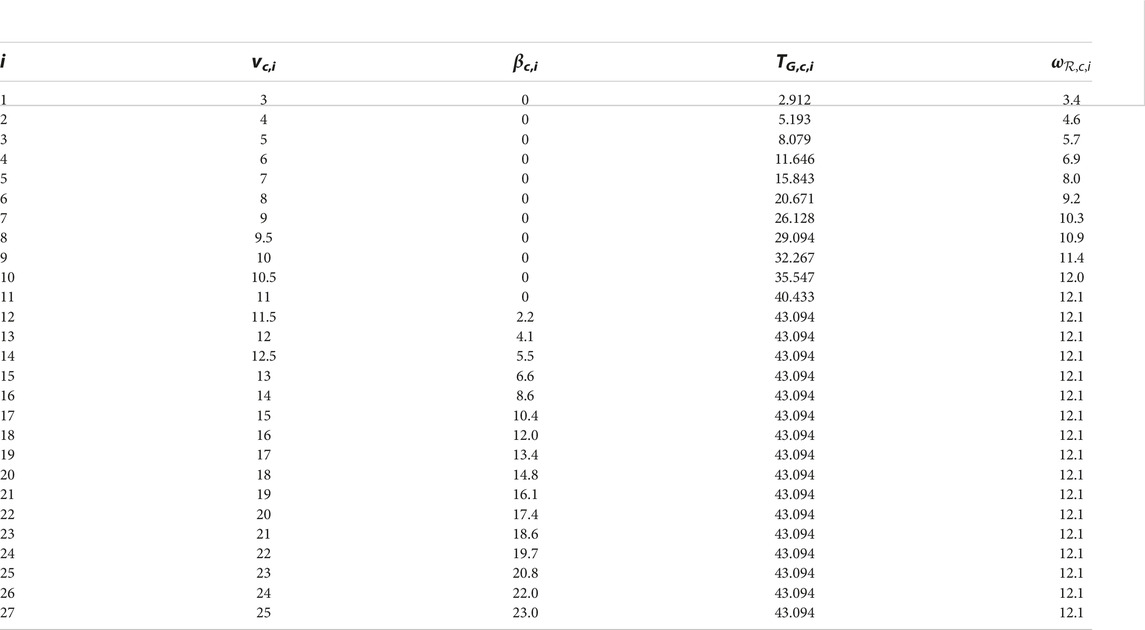
TABLE A1. States of the i steady state operations points OPi of the NREL FAST 5MW reference wind turbine with the wind speed vc,i, rotor rotational speed
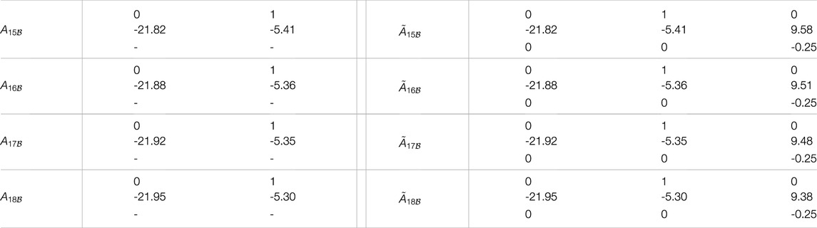
TABLE A2. State matrices
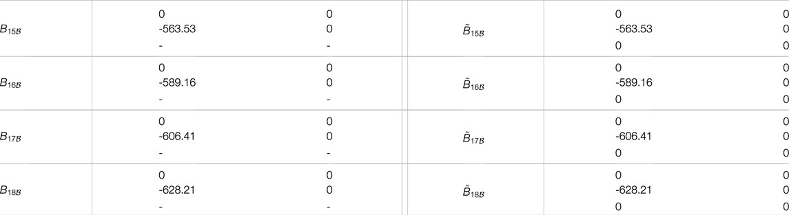
TABLE A3. Input matrices

TABLE A4. Common output matrix
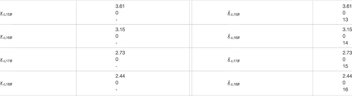
TABLE A5. Steady states

TABLE A6. Steady state pitch angle βc,i and generator torque TG,i (for the submodels i ∈ [15,18]).

TABLE A7. State feedback matrices
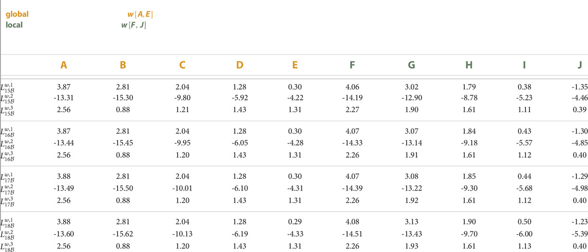
TABLE A8. Error state feedback gain matrices
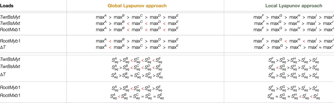
TABLE A9. Analysis of the ultimate loads maxw and fatigue loads
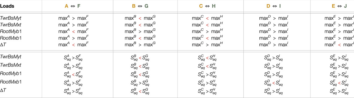
TABLE A10. Analysis of the ultimate loads maxw and fatigue loads
Keywords: global and local Lyapunov approach, Takagi–Sugeno framework, model-based controller and observer design, feedforward-feedback control, linear-matrix-inequality and pole region-based controller design, wind turbine application, elaborated wind turbine simulation model, load analysis
Citation: Frontiers Production Office (2023) Erratum: Global versus local Lyapunov approach used in disturbance observer-based wind turbine control. Front. Control. Eng. 4:1279811. doi: 10.3389/fcteg.2023.1279811
Received: 18 August 2023; Accepted: 18 August 2023;
Published: 03 November 2023.
Approved by:
Frontiers Editorial Office, Frontiers Media SA, SwitzerlandCopyright © 2023 Frontiers Production Office. This is an open-access article distributed under the terms of the Creative Commons Attribution License (CC BY). The use, distribution or reproduction in other forums is permitted, provided the original author(s) and the copyright owner(s) are credited and that the original publication in this journal is cited, in accordance with accepted academic practice. No use, distribution or reproduction is permitted which does not comply with these terms.
*Correspondence: Frontiers Production Office, cHJvZHVjdGlvbi5vZmZpY2VAZnJvbnRpZXJzaW4ub3Jn