 Timothy Sands
- Sibley School of Mechanical and Aerospace Engineering, Cornell University, Ithaca, NY, United States
Robot systems like automated shipping swinging robots, wire transducer sensors and even computer indigenous time sensors (amongst others) often use oscillating circuits such as the famous van der Pol system, while this manuscript investigates protection of such sensor circuitry to spurious voltage spikes accompanying an electromagnetic pulse. These spurious voltages can lead to uncontrolled robot motion and even debilitation. A very brief discussion of electromagnetic pulses yields design parameters to evaluate circuit responses to realistic disturbing pulses. Recent research in nonlinear-adaptive methods to protect circuits are described to highlight the proposed novelty: utilization of feedback rules as adaptive mechanisms to modify the otherwise nonlinear feedforwards systems improving the results in recent literature. Feedback is iterated to select adaption parameters that simultaneously produce favorable circuit performance in addition to effective parameter identification inherent in the adaption (to provide meaningful parameter estimates to unspecified future applications). Spurious voltages were rapidly rejected with a mere 0.3% trajectory deviation, stabilizing quickly with a final (steady state) deviation of 0.01%. The demonstrated abilities to reject the deleterious spurious effects are compared to nominal figures of merit for timing accuracy of various computer systems to conclude the proposed methods are effective for some applications, but insufficient for others.
Introduction
Robotic systems often use the chaotic van der Pol oscillator. Dutra et al. (2003) and Naoki et al. (2008a) and Roy and Demiris (2005) each articulate van der Pol used for bipedal locomotor robotics, where the implementation in (Naoki et al., 2008b) regards myriapod robots. Veskos and Demiris (2005) illustrates utilization of the van der Pol equation for swinging robots. Jasni et al. (2012) illustration van der Pol manifest as central pattern generation for quadrupled robots. Amongst the ubiquitous robotic applications of the chaotic, nonlinear van der Pol equation, this manuscript will select robotic computer systems’ indigenous timing circuits to evaluate the efficacy of the proposed methods and comparison will be made to typical capabilities of computers-usage to discern practical applicability of the achieved robustness performance. The IEEE-1588 precision timing-protocols (PTP) are a proven technology that synchronizes the internal clocks of PTP-enabled Ethernet devices such as robots, control systems, and components to create synchronized, systemwide timestamps (Harris, 2021a) The protocol is also used for time synchronization in modular collaborative robots (Gutiérrez et al., 2018). The most common way to sync robot time is with the Network Time Protocol (NTP) (David, 2014). The impact on these protocols and devices and others will be evaluated with imposition of electromagnetic pulse.
This section introduces electromagnetic pulse and very briefly describes the factors influencing the resulting voltages on distant systems and subsequently studies adaptive methods to protect electronic system timing circuits from the deleterious effects of the voltage imposition. The description of electromagnetic pulse (Electromagnetic Pulse) is intentionally abbreviated to emphasize the proposed methods to counter the resultant deleterious effects. The effects will manifest as displaced circuit timing and the displacement will be compared to figures of merit presented in Results for the aforementioned devices and protocols to ascertain the ability to continue operations despite the imposition of electromagnetic pulse.
Electromagnetic Pulse
Electromagnetic pulses are produced in lightning events and in nuclear detonations (Nanevicz et al., 2021). Reference (Nanevicz et al., 2021) and (Rabinowitz, 1986) describe the various kinds of electromagnetic pulse, while (Zhou et al., 2019) elaborates on effects of lighting-induced electromagnetic pulse on electronics inside nacelles of wind turbines. Kim and Jeong (2019) investigated effects of electromagnetic pulse on Korean power systems. This manuscript investigates mitigation of any application utilizing a certain class of electronics.
Electromagnetic pulse as often characterized by relatively slow (lasting
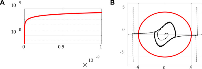
FIGURE 1. Eq. 1 achieving steady state in rougly a nano-second and inherent dynamic of van der Pol as a timing circuit. (A)Eq. 1 time (abscissa) evolution of energy (ordinant). (B) Inherent dynamic limit cycle inside desired, regular circular trajectory of radius = 5 in state space with state (abscissa) and rate (ordinant).
In accordance with Eq. 2 of reference (Rabinlowitz, 1987), the power per electron is on the order of
“At any instant the energy radiated by the ensemble of Compton electrons is stored equally in the electric and magnetic fields in the oscillating electromagnetic waves. This energy cannot exceed the accumulated earth-directed part of the gamma energy at any instant of time.” (Rabinlowitz, 1987).
From (Rabinlowitz, 1987), the total energy density delivered in time, t by the transient electromagnetic pulse is the integral of the Poynting vector, while energy balance the total energy release can be used to find the total gamma energy. The power radiated per (nonrelativistic accelerated) electron is such that electrons orbit circularly with roughly constant pitch and radius and if acting independently radiate at most about
The Compton electrons have energy equally stored in magnetic and electric fields, establishing a reasonable fundamental limit of electromagnetic pulse energy, which cannot exceed the earth-directed portion of accumulated gamma energy at any time, t. The skin depth of charge on the impinged object is affected by the atmospheric conductivity (affecting the energy reaching the object) and the conductivity of the impinged object. The electric field strength,
Considering realistic limitations on voltages imparted by electromagnetic pulse energy at a distance, the research in this manuscript utilizes a conservative imposition of a megavolt in a microsecond (notice the time of imposition in Figure 1A’s plot of Eq. 1’s time-evolution of energy) and seeks to assess the ability of adaptive van der Pol timing circuits to resist the deleterious effects of the imposed voltages. Particularly, notice in Figure 1 the movement towards roughly steady state prior to 1 microsecond.
Electronic System Timing Circuits
Timing circuits (for example those in Figure 2) (Timer Circuits: Digital C, 2021; Sekikawa et al., 2011; Van der Pol oscillator La, 2021) utilize capacitors as their basis, where the time constant of the capacitor is the product of the resistance and capacitance producing predictable capacitor charge and discharge curves for both voltage and current, and their governing equations are highly nonlinear and are often described as “chaos” as depicted in Figure 1B, where the bifurcation or transition from a fixed-point to limit cycle behavior is called a Hopf bifurcation (Patil et al., 2020). Cooper et al. (2017) introduced adaptive notions of controlling chaos [with respect to the van der Pol oscillator in Eq. 2, and this manuscript evaluates the use of those methods to provide resiliency to the deleterious effects of electromagnetic pulse induced voltages. The van der Pol oscillator is applicable to several fields of endeavors including brain science (Patil et al., 2020) and even dynamics of phase synchronization between solar polar magnetic fields (Savostianov et al., 2020)], so the proposed methods in this manuscript become generalizable. Using the proposed methods, the goal is to force the system to respond with a perfect circle in phase space rather than the chaotic limit cycle displayed in Figure 1B, despite the imposition of a large, rapid voltage spike from an electromagnetic pulse.
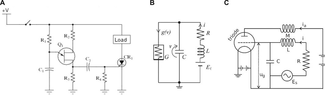
FIGURE 2. Representative van der Pol circuits utilizing capacitors to establish predictable charge and discharge curves. (A) Relaxation oscillator used as a timing circuit which outputs a square wave signal. (Rabinlowitz, 1987). (B) Representative van der pol circuit. (C) Representative van der Pol circuit (Van der Pol oscillator La, 2021).
Materials and Methods
Adaptive Methods to Protect Electronic System Timing Circuits
Protection from electromagnetic pulse is ubiquitously achieved by shielding efforts (Lee et al., 2020; Jang et al., 2020), whereas this manuscript proposes passive mitigation by adopting adaptive electronics capable of countering the effects of the transient voltages. Following the successful implementation of nonlinear adaptive methods to spacecraft attitude control (Sands et al., 2007; Sands et al., 2009; Sands et al., 2012)
This section provides a concise and precise description of the experimental (simulation) results, their interpretation, as well as the experimental conclusions that can be drawn. Simulations were created in MATLAB/SIMULINK software version R2020A with variable step size and automatic solver selection. Eq. 3 is encoded with the desired trajectories (subscripted
Adaptive Methods to Protect Electronic System Timing Circuits first illustrates gain tuning of the parameters in the adaption rule and the selected adaption rule gains are used in Results’s comparison of adaptive circuit performance estimating unknown parameter
Estimation by Adaption Rule With Proportional, Derivative, and Integral Components
This section illustrates iterative adaption gain tuning in 3 degrees displayed in Figures 3A,B, while Figure 3C displays the results of the chosen adaption gain selection. For ease of reading, each subfigure’s caption contains a mini table containing relevant information for each respective iteration corresponding to the figure.
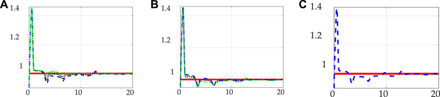
FIGURE 3. Adaption gain(s) iteration to minimize mean estimation error. (A)
Figure 4 compares nominal circuit performance to the case of imposition of a megavolt over a microsecond. Figures 4A,B depict nominal performance with the abscissa of Figure 4B zoomed to amplify the initial transient response (which is duplicated in the first period less than 30 s in Figure 4D). Figures 4C,D display timing circuit performance with event imposition at 30 seconds. Notice the comparison of Figures 4A,C. The topmost and lowest portions of the circular trajectory have identical transient startup, while the upper (middle) portion of the circular trajectory includes a new additional transient associated with the disturbance at 30 seconds.

FIGURE 4. Nominal performance without electromagnetic pulse. (A)
Qualitatively, the circuit seems quite resilient in the fact the nominal circular trajectory is merely mildly disturbed. The deviation off the circular path produces an incrementally longer time-period to complete the circle, and this time-period embodies the deleterious effects. If this additional time results in loss of clock synchronization, for example, the electronic system using this timing circuit could be rejected from network access with other systems using the same time synchronization.
Results
Comparison of Nominal Results (No Electromagnetic Pulse) and Results With Electromagnetic Pulse
Running identical simulations for 60 s affords an opportunity for direct comparison to reveal the timing impacts of the transient electromagnetic pulse. While Figure 4D displays the resulting tracking error, Figure 5 displays the accuracy of identification of
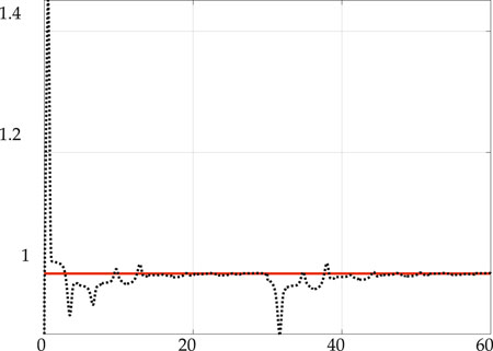
FIGURE 5. Coefficient adaption in simulation of 1 MV with 1 microsesecond pulsewidth disturbance resulting from electromagnetic pulse at 30 s

TABLE 1. Adaption gain
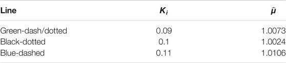
TABLE 2. Adaption gain

TABLE 3. Selected Gains.
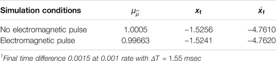
TABLE 4. Performance comparison1.
Impacts on Timing Circuit Performance
Comparison of Nominal Results (No Electromagnetic Pulse) and Results With Electromagnetic Pulse revealed timing disruption was substantially overcome by the proposed adaptive circuit, but the disruption was not zero, as displayed in Figure 6. The period of oscillation was delayed 1.55 milliseconds and trajectory deviation was essentially stabilized during the transient electromagnetic pulse exhibiting a mere 0.3% trajectory deviation stabilizing quickly with a final (steady-state) deviation of 0.01%. This section compares the simulated timing disruption to figures of merit for timing maintenance of various systems utilizing timing circuits amongst other timing sources. A 2014 white paper published by MicroSemi includes many such figures of merit for representative systems.
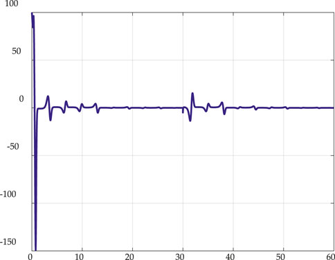
FIGURE 6. Trajectory radial deviation (percent) in 60 s simulation with imposition of electromagnetic pulse at 30 s. Mean deviation including startup transient: 0.0272 (0.5440%); mean deviation after imposition of electromagnetic pulse: −0.0169 (−0.3380%); final deviation: 5.5903e−04 (0.0112%).
“Most network operations (e.g., online security, log file updates) require accuracy on the order of 1–10 milliseconds. Depending on the specific application, electric utilities may require time measured in microseconds. Most financial and general business applications require accuracy in the 100 millisecond to 10 s range—even if only to accurately establish the order of events….Even if set to an absolutely accurate time reference, a PC clock may still be off by 50 milliseconds at the very instant when it is set. Then, once set, the clocks in computers will start to drift, some by as much as several minutes a day. It is possible for a workstation to achieve consistent accuracy of half-a-millisecond, but only if its clock is reset repeatedly over the course of a day.” (Microsemi White Paper, 2014).
Consider the electric power industry “…operators have to phase synchronize generators running hundreds of miles apart. In addition, they also must monitor the power grid for events such as voltage spikes or equipment outages using systems known as SCADA (supervisory control and data acquisition). SCADA systems are heavy users of time synchronization technology—specifically GPS time servers—and timestamps are a major reason why. Timestamps from these servers provide the critical evidence needed to identify the causes of power failures, such as the one that crippled the Northeastern United States and Ontario in August 2003.” (Microsemi White Paper, 2014).
“On a WAN, NTP client time accuracy can be as good as 10–50 milliseconds on average, whereas individual time corrections can frequently vary by quite a bit more. However, if UTC is provided via GPS to the LAN, NTP can usually distribute UTC locally with an accuracy of one to 2 milliseconds to the clients. (GPS time stamp accuracy inside the time server is typically about a few microseconds to UTC). That means for most organizations, and for most applications, a GPS referenced time server is sufficient to deliver time to the local net and distribute time to client machines once available.” (Microsemi White Paper, 2014).
While Table 4 indicates a representative 1.5 milliseconds impact to oscillation period, Table 5 lists several instance of typical timing synchronization capabilities and requirements to bestow intuition on the ability of the proposed method to maintain nominal performance amidst an electromagnetic pulse event and quickly re-establish nominal performance.
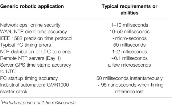
TABLE 5. Timing synchronization requirements or typical abilities1 [Relyum Team, 2021b; Synchronizing Industrial, 2016].
Several application areas have timing requirements for synchronization that indicate efficacy of the proposed method (e.g., WAN networks, personal computers) and some applications that require such tight timing abilities or requirements to render the proposed method ineffective (e.g., IEEE 1588 Precision Time Protocol, and GMR1000 Master Clocks).
Discussion
Use of the van der Pol chaotic equation is perhaps ubiquitous in robotics, e.g., automated shipping swinging robots, wire transducer sensors and even computer indigenous time sensors (amongst others). This manuscript proposed a new method to increase robustness of these applications to the deleterious effects of spurious environmental electromagnetic fields, while focusing on robot computer systems for comparison, since figures of merit are readily available without needing to model and simulate other potential applications. The results presented using the proposed adaption mechanism indicate efficacy for some applications (e.g., particularly personal computer and network electronics) while not sufficient for others (e.g., applications requiring IEEE 1588 Precision Time Protocol and industrial automation applications requiring accuracy akin GMR1000 master clock). The main strength seems to be the robust rejection of the transient voltages with minimal deviation potentially preventing loss of timing synchronization following an electromagnetic impulse event from solar sources, lightning, nuclear detonations, etc.
Cooper, et al. used Eq. 2 to formulate Eq. 3 in accordance with principles of so-called physics-based controls as taught by Lorenz (2021a), Lorenz (2021b) and attempted to augment the physics-based feedforward with classical feedback optimized in a linear-quadratic sense, but the augmentation performed very poorly. Thus, this manuscript instead sought to use classical feedback principles (not yet optimized) to perform the function of parameter adaption rather than to formulate the feedback control signal. Future research should investigate the burgeoning application of deterministic artificial intelligence methods (D.A.I.) (Sands, 2020) which seem to promise improved performance over nonlinear adaptive methods (Sands et al., 2007; Sands et al., 2009; Sands et al., 2012) like the one proposed here. D.A.I. re-introduces optimization in the feedback learning channel whose instantiation constitutes a key difference between nonlinear adaption as utilized here and D.A.I. as taught at Cornell University (Sands, 2020; Shah and Sands, 2021).
Comparison to Alternatives
Having illustrated efficacy of the proposed method to counter deleterious effects of the imposition of a megavolt in a microsecond, Table 6 displays comparison of the results validated in Results to the efficacies of alternatives. Three alternatives are examined: surge protectors, unregulated power strips, and electromagnetic pulse shields. Surge protectors are arguably ubiquitously known, since they are common household devices protecting home electronics against sudden voltage spikes on the order of hundreds of volts imposed over microseconds after a few nanoseconds delay. Unregulated power strips are often described differently than surge protectors, since many do not truly use grounding techniques similar to surge protectors.
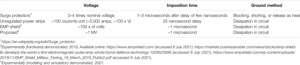
Electromagnetic pulse shields are very recently touted as capable or protection against electromagnetic pulse generated by lightning by comparison to military standards for such protection, although subsequent publications highlight the issue that protection should not be claimed too broadly. Protection against the effects of electromagnetic pulse generated by high altitude nuclear detonations necessitates rejection of very high voltages. A noteworthy validation was experimentally performed and the capabilities are coarsely summarized in Table 6. The proposed methodology indicates efficacy at much higher voltage levels.
Conclusion
This manuscript proposed, analyzed, and validated in simulation where spurious voltages were rapidly rejected with a mere 0.3% trajectory deviation, stabilizing quickly with a final (steady state) deviation of 0.01%. The demonstrated abilities to reject the deleterious spurious effects are compared to nominal figures of merit for timing accuracy of various computer systems to conclude the proposed methods are effective for some applications, but insufficient for others. The proposed method illustrated capabilities to reject a megavolt, while typical alternatives reject hundreds of volts.
Data Availability Statement
The raw data supporting the conclusions of this article will be made available by the authors, without undue reservation.
Author Contributions
The author confirms being the sole contributor of this work and has approved it for publication.
Conflict of Interest
The author declares that the research was conducted in the absence of any commercial or financial relationships that could be construed as a potential conflict of interest.
Publisher’s Note
All claims expressed in this article are solely those of the authors and do not necessarily represent those of their affiliated organizations, or those of the publisher, the editors and the reviewers. Any product that may be evaluated in this article, or claim that may be made by its manufacturer, is not guaranteed or endorsed by the publisher.
Acknowledgments
The foremost development at the heart of the methods proposed in this manuscript arise from the physics-based methodology taught by Professor Robert Lorenz (Lorenz R., 2021) who recently posthumously was named a Fellow of the National Academy of Engineering in the United States. Readers may see this methodology at the heart of several methods, not at least nonlinear adaptive control (Sands et al., 2007; Sands et al., 2009; Sands et al., 2012)
Footnotes
1Available online: https://en.wikipedia.org/wiki/Surge_protector#Voltage_spikes(accessed 8 July 2021).
2Available online: https://www.empshield.com/(accessed 8 July 2021).
3Available online: https://markets.businessinsider.com/news/stocks/emp-shield-llc-develops-the-world-s-first-electromagnetic-pulse-emp-whole-home-defence-technology-1028523996 (accessed 8 July 2021).
4Available online: https://www.empshield.com/wp-content/uploads/2019/11/EMP_Shield_Military_Testing_16_March_2019_Public2.pdf (accessed 9 July 2021) Copyright: © 2021 by the authors. Submitted for possible open access publication under the terms and conditions of the Creative Commons Attribution (CC BY) license (http://creativecommons.org/licenses/by/4.0/).
References
Relyum Team (2021b). Solving the Synchronization of NTP Referenced SCADA Systems Connected to IEEE 1588 High-Availability Networks. Relyum. By Soce. Available online: https://www.relyum.com/web/wp-content/uploads/2019/09/relyum-pcie_scada_ntp_syncronization-190919_lq.pdf (Accessed January 21, 2021).
Cooper, M., Heidlauf, P., and Sands, T. (2017). Controlling Chaos-Forced van der Pol Equation. Mathematics 5 (4), 70. doi:10.3390/math5040070
David, K. (2014). Time and Clock Synchronization. Available online: http://robotsforroboticists.com/timing-synchronization/ (Accessed February 23, 2021).
Dutra, M. S., de Pina Filho, A. C., and Romano, V. F. (2003). Modeling of a bipedal locomotor using coupled nonlinear oscillators of Van der Pol. Biol. Cybernetics 88 (4), 286–292. doi:10.1007/s00422-002-0380-8
Flügge-Lotz, I. (1971). Memorial to N. Minorsky. IEEE Trans. Automat. Contr. 16 (4), 289–291. doi:10.1109/TAC.1971.1099734
Gutiérrez, C., Juan, L., Ugarte, I., GoenagaKirschgens, I. L., and Vilches, V. (2018). Time Synchronization in Modular Collaborative Robots. arXiv:1809.07295.
Harris, K. (2021a). Precision System Synchronization with the IEEE-1588 Precision Time Protocol (PTP). Available online: https://www.flir.com/discover/iis/machine-vision/precision-system-synchronization-with-the-ieee-1588-precision-time-protocol-ptp/ (Accessed February 23, 2021).
Jang, J.-M., Lee, H. S., and Singh, J. K. (2020). Electromagnetic Shielding Performance of Different Metallic Coatings Deposited by Arc Thermal Spray Process. Materials 13, 5776. doi:10.3390/ma13245776
Jasni, F., and Shafie, A. A. (2012). “Van Der Pol Central Pattern Generator (VDP-CPG) Model for Quadruped Robot,” in Trends in Intelligent Robotics, Automation, and Manufacturing. IRAM 2012. Communications in Computer and Information Science. Editors S. G. Ponnambalam, J. Parkkinen, and K. C. Ramanathan (Berlin, Heidelberg: Springer), Vol. 330, 167–175. doi:10.1007/978-3-642-35197-6_18
Kim, S., and Jeong, I. (2019). Vulnerability Assessment of Korean Electric Power Systems to Late-Time (E3) High-Altitude Electromagnetic Pulses. Energies 12, 3335. doi:10.3390/en12173335
Lee, H. S., Park, J. H., Singh, J. K., Choi, H. J., Mandal, S., Jang, J. M., et al. (2020). Electromagnetic Shielding Performance of Carbon Black Mixed Concrete with Zn-Al Metal Thermal Spray Coating. Materials 13, 895. doi:10.3390/ma13040895
Lorenz, R. D. (2021b). National Academy of Engineering Website. Available online: https://www.nae.edu/204127/Dr-Robert-D-Lorenz (Accessed January 31, 2021).
Lorenz, R. (2021a). ME746 Dynamics of Controlled Systems. University of Wisconsin graduate course. Available online: https://aefis.wisc.edu/index.cfm/page/AefisCourse.ABETSyllabusForm?courseid=396 (Accessed January 31, 2021).
Microsemi White Paper (2014). 5 Essential Elements of Network Time Synchronization. Available online: https://www.microsemi.com/document-portal/doc_download/133205-5-essential-elements-of-network-time-syncronization#:∼:text=On%20a%20WAN%2C%20NTP%20client,two%20milliseconds%20to%20the%20clients (accessed on January 21, 2021).
Minorsky., N. (1922). Directional Stability of Automatically Steered Bodies. J. Amer. Soc. Nav. Eng. 34 (2), 280–309. doi:10.1111/j.1559-3584.1922.tb04958.x
Rabinowitz, M., “Nuclear Electromagnetic Pulse,” Encyc. Sci. Tech., (1986). McGraw-Hill: New York, USA 1985, pp. 34–47.
Nanevicz, J., Vance, E., Hamm, J., and Bubenik, D. M. (2021). Comparison of the Electromagnetic Properties of Lightning and EMP (Electromagnetic Pulse) -- Results of Recent Lightning Studies. Final technical report 30 Jun 83. Menlo Park, CA: SRI International. doi:10.21236/ada154325
Naoki, K., Yoshikatsu, H., and Nohara, B. (2008). Analysis of coupled van der Pol oscillators and implementation to a myriapod robot. IFAC Proc. 41 (2), 767–772. doi:10.3182/20080706-5-kr-1001.00132
Naoki, K., Yoshikatsu, H., and Nohara, B. (2008). Analysis of coupled van der Pol oscillators and implementation to a myriapod robot. IFAC Proc. 41 (2), 767–772. doi:10.3182/20080706-5-kr-1001.00132
Patil, G., Nalepka, P., Kallen, R. W., and Richardson, M. J. (2020). Hopf Bifurcations in Complex Multiagent Activity: The Signature of Discrete to Rhythmic Behavioral Transitions. Brain Sci. 10, 536. doi:10.3390/brainsci10080536
Rabinlowitz, M. (1987). Effect of the Fast Nuclear Electromagnetic Pulse on the Electric Power Grid Nationwide: A Different View. IEEE Trans. Power Deliv. 2 (4), 1199–1222. doi:10.1109/TPWRD.1987.4308243
Roy, P., and Demiris, Y. (2005). “Analysis of biped gait patterns generated by van der Pol and Rayleigh oscillators under feedback,” in Proceedings Of 3rd International Symposium on Adaptive Motion in Animals and Machines (AMAM2005) (Germany: Ilmenau) September 25-30.
Sands, T., Kim, J. J., and Agrawal, B. N. (2009). “Improved Hamiltonian Adaptive Control of Spacecraft,” in Proceedings of the IEEE Aerospace, Big Sky, MT, USA, 7–14 March 2009 (Piscataway, NJ, USA: IEEE Publishing), 1–10.
Sands, T., Kim, J. J., and Agrawal, B. N. (2012). “Spacecraft Adaptive Control Evaluation,” in Proceedings of the Infotech@ Aerospace. Garden Grove, CA, USAReston, VA, USA: American Institute of Aeronautics and Astronautics, 2012–2476. (June 19–21 2012).
Sands, T., Kim, J. J., and Agrawal, B. N. (2007). “Spacecraft fine Tracking Pointing Using Adaptive Control,” in Proceedings of the 58th International Astronautical Congress, Hyderabad, India, (Paris, France: International Astronautical Federation) 24–28 September 2007.
Savostianov, A., Shapoval, A., and Shnirman, M. (2020). Dynamics of Phase Synchronization between Solar Polar Magnetic Fields Assessed with Van Der Pol and Kuramoto Models. Entropy 22, 945. doi:10.3390/e22090945
Sekikawa, M., Shimizu, K., Inaba, N., Kita, H., Endo, T., Fujimoto, K. i., et al. (2011). Sudden change from chaos to oscillation death in the Bonhoeffer-van der Pol oscillator under weak periodic perturbation. Phys. Rev. E 84, 056209. doi:10.1103/PhysRevE.84.056209
Shah, R., and Sands, T. (2021). Comparing Methods of DC Motor Control for UUVs, springing from the course MAE6280 Adaptive and Learning Systems. Appl. Sci. 11 (11), 4972. Available online: https://classes.cornell.edu/browse/roster/FA20/class/MAE/6280 (Accessed February 23, 2021). doi:10.3390/app11114972
Synchronizing Industrial Automation Systems Over Ethernet (2016). IEEE 1588 PTP, NTP, Industrial Automation. Masterclock. November 30, 2016. Available online: https://www.masterclock.com/company/masterclock-inc-blog/synchronizing-industrial-automation-systems-over-ethernet (Accessed January 21, 2021).
Timer Circuits: Digital Circuits (2021). All about Circuits. Boise, ID: EETech Media, LLC. Available online: https://www.allaboutcircuits.com/worksheets/timer-circuits/ (Accessed July 21, 2021).
Van der Pol oscillator Last Edited on 12 January 2021. Available online: https://en.wikipedia.org/wiki/Van_der_Pol_oscillator (accessed January 21, 2021).
Veskos, P., and Demiris, Y. (2005). “Robot swinging using van der Pol nonlinear oscillators,” in the Proceedings of the third international symposium on adaptive motion of animals and machines (Germany: Ilmenau) September 25-30.
Keywords: control theory, learning systems, intelligent control systems, sensors and signal processing, robotics and applications, interpretation of sensor data, sensor electronics, robustness to electromagnetic pulse
Citation: Sands T (2021) Countering the Deleterious Effects of Electromagnetic Pulse. Front. Electron. 2:727994. doi: 10.3389/felec.2021.727994
Received: 20 June 2021; Accepted: 21 July 2021;
Published: 13 August 2021.
Edited by:
Tian-Hua Liu, National Taiwan University of Science and Technology, TaiwanReviewed by:
Yuchen Zhang, University of New South Wales, AustraliaChong Leong Gan, Micron, United States
Copyright © 2021 Sands. This is an open-access article distributed under the terms of the Creative Commons Attribution License (CC BY). The use, distribution or reproduction in other forums is permitted, provided the original author(s) and the copyright owner(s) are credited and that the original publication in this journal is cited, in accordance with accepted academic practice. No use, distribution or reproduction is permitted which does not comply with these terms.
*Correspondence: Timothy Sands, dGFzMjk3QGNvcm5lbGwuZWR1