Abstract
Oceanographic mooring missions are critical for advancing our understanding of the world’s oceans and their role in the broader Earth system. These missions rely on the deployment and maintenance of complex observing systems, comprising subsurface, profiling, and surface moorings, which are designed to collect valuable data from the ocean interior. The success of these missions depends on meticulous planning and strategic execution, which are facilitated by the use of Field Service Plans (FSPs). FSPs are comprehensive and adaptable planning tools that integrate safety measures, contingency plans, and timelines to ensure the successful and safe recovery, maintenance, and deployment of mooring systems. In this paper, we provide a comprehensive guide to drafting, implementing, and adapting FSPs tailored to the unique challenges posed by oceanographic mooring missions. We highlight the critical role of FSPs in optimizing safety, data quality, and mission success, while also underscoring the need for flexibility and adaptation. Our aim is to provide practical guidance and a template for researchers, expedition leaders, and institutions engaged in oceanographic research.
1 Introduction
Oceanographic research makes extensive use of observing system networks, which allow for the collection of valuable data from the ocean interior. This is crucial for gaining deeper insights into the dynamic interactions between the ocean and the Earth’s climate system. Oceanographic moorings, which can be subsurface, profiling, or surface-based, have become instrumental platforms for sustained ocean observations at fixed stations (Tanhua et al., 2019).
The deployment and maintenance of these moorings are essential for climate change research. Scientists recognize the importance of long-term data records for an accurate characterization of complex interactions. Sustained time-series records are the most effective observational tool, for not only identifying but also understanding global change and its impacts (Send et al., 2010). However, the deployment and maintenance of oceanographic moorings integrate multiple complex challenges. These challenges span from the harsh environmental conditions of the open sea, characterized by turbulent seas and adverse weather, to the need for careful data handling and quality control, ensuring the integrity of the scientific dataset.
The Global Ocean Observing System (GOOS) is a collaborative initiative that includes various networks like OceanSITES. These networks collect, deliver, and promote the use of high-quality data from long-term, high-frequency observations in the open ocean (IOC, 2019). OceanSITES makes ocean observations at fixed locations in the open ocean, covering a wide range of essential ocean variables and disciplines (Send et al., 2010; Weller et al., 2019). The high temporal resolution sampling of these measurements allow for the detection of rapid processes and events, providing extensive observations from the sea surface to the seafloor. This breadth of data is particularly advantageous in locations where monitoring with mobile platforms is difficult or impractical, such as straits, passages, and boundary currents. OceanSITES relies on best practices (e.g. Coppola et al., 2016, and Venkatesan et al., 2018), that are published in the Ocean Best Practices System Repository (OBPS-R), an open access, permanent, digital repository of community best practices in ocean-related sciences and applications maintained by the International Oceanographic Data and Information Exchange (IODE) of the UNESCO-IOC as an IOC (IODE, GOOS) coordinated activity. Along with other observational platforms – such as profiles and gliders – measurements from moorings serve several valuable purposes, such as assessing the performance of satellite and floats, validating numerical models, accommodating diverse sensors, contributing to ongoing innovation in observational technology.
The Istituto di Scienze Marine (ISMAR) of the Italian Consiglio Nazionale delle Ricerche (CNR) has nearly four decades of experience in maintaining deep submerged moorings across the Mediterranean Sea (Ligurian Sea, Sicily Channel, Tyrrhenian Sea, Ionian Sea, Adriatic Sea, for an overview see Ravaioli et al., 2016). Since 1993, CNR-ISMAR has maintained two moorings in the Sicily Channel (Schroeder et al., 2017). The successful, regular maintenance of these moorings – central to our oceanographic missions – has relied on Field Service Plans (FSPs), which are methodically constructed roadmaps for field operations.
While CNR-ISMAR’s FSP have proven effective for us over the past three decades of hands-on experience, it is important to recognize that other oceanographic institutes have also developed their own systems, tailored over years of practical experience. These systems, which may be equally suitable, reflect the diverse approaches and methodologies adopted globally. The primary aim of this paper is to formalize and disseminate CNR-ISMAR’s FSP as a comprehensive resource for the oceanographic community. By detailing the main components of our FSP and their synergistic interactions, we seek to highlight the importance of careful planning in optimizing field service operations, ensuring safety, and maximizing scientific output. This document is intended to complement, not to replace, the variety of effective systems already in place globally, fostering collaboration and shared learning within the field.
2 A brief overview of fixed open ocean platforms and moorings
Fixed-site open ocean platforms and moorings are crucial for collecting data across the ocean-atmosphere interface, coastal areas, the seabed, and the ocean’s interior. With the integration of advanced sensors and data transmission devices, these moorings measure a wide array of parameters, from physical to biogeochemical, biological, and sedimentological.
The configuration of these platforms is determined by the physical processes under study, the environmental constraints of the deployment area, and the monitoring project’s duration. Traditional seafloor-anchored mooring lines (surface, subsurface or with profiling elements), seabed platforms, buoys, and cabled observatories each offer unique observational strengths and can be deployed individually or in arrays to augment regional monitoring capabilities.
Despite their benefits, these systems face challenges such as high installation, operation, maintenance, and data management costs. These can be mitigated by frequent data transmission, extending operational lifetimes without servicing, and reusing and refurbishing components. Engineering advances are also reducing costs with improved power systems, sensors, and more durable materials (Meindl, 1996).
To ensure clarity throughout this manuscript, we define the following terms: “subsurface mooring”, a system anchored to the seabed with floats and acoustic releases, with no surface element; “surface mooring”, as the previous, but with a surface element; “profiling mooring”, as the previous, but equipped with a profiling element; “seabed platform”, a standalone unit for continuous high-resolution seabed data acquisition; “oceanographic buoy”, a floating structure anchored to the seabed, equipped with oceanographic and meteorological instruments; “cabled observatory”, a seabed platform linked to onshore facilities via a cable for near real-time data access. For the scope of this paper, in the following we will use the term “mooring” or “oceanographic mooring” to indicate surface or subsurface moorings. These consist of connected rope segments with instruments for self-recording or real-time data transmission. In the following section, we detail the components of “subsurface moorings” since this is the mooring type maintained by CNR-ISMAR.
2.1 Subsurface mooring components
The primary components of an oceanographic subsurface mooring system are anchors, floating devices, acoustic releases and rope segments, onto which a multitude of various sensors can be mounted at pre-defined depths. Careful sizing of the anchor, selection of rope materials, and integration of release systems are essential considerations in mooring design and deployment. Anchors are typically heavy materials like railroad wheels or concrete blocks and are the expendable elements of a mooring (i.e., they will not be recovered after each deployment period). Ropes are usually synthetic fibers or nylon, forming the structural backbone to which the sensors and floating devices are attached. These rope segments are linked through shackles, rings, and swivels to form a continuous line, potentially terminating with a thimble at each end. In order to provide the buoyancy needed to counterbalance the weight of instruments and other components, spherical floatation devices are used, which are often made of synthetic foam or glass covered with protective plastic. These can be interspersed between segments of the mooring line or mounted directly on the rope, in a way that best facilitates the recovery process. Given that at predefined time intervals the mooring systems need to be serviced (recovery, cleaning, inspection, data retrieval, battery change, components replacements, and re-deployment), a release system is needed. For this an acoustic transponder is mounted between the anchor and the rope, which can be activated by a unique acoustic signal, allowing the controlled release of the mooring. Multiple releasers, configured in tandem, enhance the probability of successful recovery (Coppola et al., 2016).
2.2 The SiCO observatory
The SiCO observatory, established in 1993 by CNR-ISMAR, is a twin-mooring system located in the Sicily Channel, a strategic point connecting the Eastern and Western Mediterranean Sea. It consists of two subsurface moorings aligned in parallel trenches across a 150 km transect between Tunisia and Sicily. These moorings, which are part of the HYDROCHANGES and OceanSITES observing networks, have been regularly serviced every six months since their inception. SiCO represents one of the longest-running Mediterranean time series, tasked with monitoring thermohaline properties and water mass exchanges. It is equipped with current profilers and CTD probes (Table 1).
Table 1
| SiCO1 | SiCO2 |
|---|---|
| Current Profile (ADCP): range 410 – 10 m | Current Profile (ADCP): range 410 – 10 m |
| Temperature (ADCP): 410 m | Temperature (ADCP): 410 m |
| Pressure (ADCP): 410 m | Pressure (ADCP): 410 m |
| Temperature (CTD-O2 probe): 400 m | Temperature (CTD-O2 probe): 400 m |
| Conductivity (CTD-O2 probe): 400 m | Conductivity (CTD-O2 probe): 400 m |
| Pressure (CTD-O2 probe): 400 m | Pressure (CTD-O2 probe): 400 m |
| Dissolved Oxygen (CTD-O2 probe): 400 m | Dissolved Oxygen (CTD-O2 probe): 400 m |
| Temperature (T-probe): 80 m | Temperature (T-probe): 80 m |
Variables measured and depths of the measurements.
Through its deployment, SiCO has enabled the detailed monitoring of the Intermediate Water’s (IW) thermohaline properties, revealing significant temperature and salinity trends (Figure 1) that surpass those at similar depths in the global ocean by at least an order of magnitude (Schroeder et al., 2017). The primary objective of SiCO is to explore the causes behind these observed trends, and in particular the role of a changing climate over the Mediterranean. The observatory’s long-term data reveals how fast the response to climate change can be in a marginal seas compared to the global ocean. This demonstrates also the indispensable role of long time series in the ocean.
Figure 1
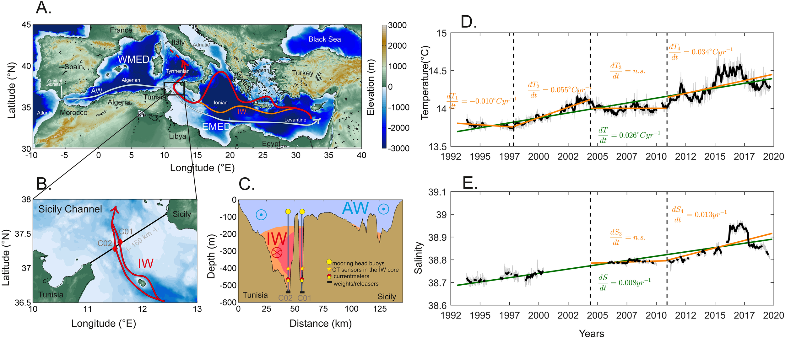
(A) The Mediterranean Sea with circulation schemes for Atlantic Water (AW, light blue arrow) and the Intermediate Water (IW, red arrow), black rectangle indicates the monitored area; (B) zoom on the Sicily Channel with the positions of the two moorings (red diamonds), that intercept both branches of the bifurcated IW flow (red arrow); (C) vertical schematic section of the Tunisia - Sicily transect [black line in (B)], showing the two-layer system of water masses flowing in opposite directions (AW eastward; IW westward) and the positions of instruments on the moorings; time series of (D) temperature and (E) salinity at 400 m depth (mooring SiC02) (updated from Schroeder et al., 2017).
In this context, the SiCO observatory serves as an exemplary model for showcasing the practical application of an FSP.
3 The field service plan
The recovery, maintenance and deployment of oceanographic moorings are activities characterized by complexity, challenges, and inherent risks, demanding precise planning and execution. While existing handbooks (Coppola et al., 2016) offer comprehensive guidelines and best practices for data collection across the entire infrastructural chain, our focus lies specifically on the strategic planning and operational procedures inherent to mooring operations. The design that at CNR-ISMAR guides these operations and ensures their careful planning and execution is the Field Service Plan (FSP). This section highlights the significance of the FSP in our oceanographic mooring missions and the multiple benefits of a well-structured FSP.
3.1 The role of a FSP
There are a number of aspects that make the FSP essential for a successful managing strategy, going from its operational efficiency, the adoption of safety protocols, the allocation of resources, the integrity of the collected data, the compliance assurance. In particular, the FSP may serve as a roadmap, delineating each phase of a mooring management operation, by providing clarity of purpose and ensuring that every task is executed with precision, minimizing operational inefficiencies and errors.
Safety is paramount in oceanographic expeditions, thus the FSP also includes safety measures and contingency plans into every aspect of the operation, contributing itself to fostering a culture of safety among scientific personnel and crew. In order to ensure the collection of high-quality scientific data, the FSP outlines data management and quality control protocols, safeguarding data integrity. Finally, given that oceanographic mooring operations are subject to a multitude of regulations and permits, the FSP also ensures that all legal and regulatory obligations are met, mitigating the risk of operational disruptions and regulatory non-compliance.
Thus, a well-structured FSP yields multiple benefits throughout the entire lifecycle of a mooring management. By means of a rigorous planning, the FSP helps in organizing operations, optimizing resource utilization and minimizing downtime, guaranteeing operation efficiency at the same time. This efficiency ultimately results in cost savings, contingency preparedness, high-quality data, as well as maximized scientific productivity. For a mooring management team, the FSP is the basis to ensure the successful and efficient execution of oceanographic mooring operations.
It is important to stress that before going at sea, or during a first briefing on board of the vessel, the FSP should be illustrated to all scientific and technical people on board, defining the role of each person involved in the operations. Indeed, when the recovery/deployment operations start, there is no more time to explain what to do to not expert people, especially if the operations are done during rough sea conditions.
Finally, to ensure the collection of high-quality data from oceanographic moorings, it is essential to adhere to minimum sampling standards. These standards include sensor accuracy, precision, and sampling frequency, which are critical for capturing the dynamic processes of the ocean. Sensor accuracy refers to the degree to which a measured value reflects the true value, while precision indicates the consistency of repeated measurements. Sampling frequency must be carefully considered based on the specific oceanographic processes being studied; higher frequency sampling may be necessary for rapidly changing conditions, whereas lower frequency may suffice for more stable environments. Furthermore, in developing and put into practice a FSP for oceanographic moorings, it is important to align with established oceanographic best practices and guidelines (for instance the Ocean Best Practices System, or OBPS, backed by the IOC through IODE and GOOS).
3.2 Components of a FSP
The FSP is composed by multiple crucial components that collectively ensure the success of oceanographic mooring operations. Each component listed below is instrumental in organizing and executing the mission effectively. They will be further detailed in the full FSP example provided in section 4.
-
- Equipment lists and mooring diagrams
-
- Safety measures and contingency plans
-
- Stakeholder communication
-
- Timeline
-
- Pre-cruise activities
-
- Recovery procedures
-
- Maintenance operations
-
- Deployment procedures
-
- Data handling and quality control
-
- Data archiving and reporting
-
- Post-cruise analysis and scientific reporting
These components collectively form a robust framework for mooring operations, ensuring that safety, data quality, and mission objectives are met efficiently and responsibly. A detailed example for each component is aimed at provide practical guidance for mission planning and execution.
4 Example of a field service plan
4.1 Review and approval
The FSP is subject to thorough review and approval by all pertinent stakeholders to ensure alignment and consensus before its implementation begins. This collaborative process guarantees that the plan reflects the collective expectations and requirements of all involved parties.
4.2 Objectives and scope
4.2.1 Objectives of the field service plan
-
Ensure long-term monitoring: The primary objective of the FSP is to facilitate the long-term monitoring of marine circulation between the Eastern and Western Mediterranean through the SiCO mooring system.
-
Maintenance and instrument integrity: The FSP aims to ensure the continued functionality and integrity of the SiCO mooring system, including currentmeters (ADCPs, i.e. Acoustic Doppler Current Profilers) and multiparametric probes (CTD, i.e. Conductivity, Temperature, and Depth, + dissolved oxygen).
-
Data collection and quality: To collect high-quality oceanographic data, including vertical current profiles and hydrological parameters, which are essential for ongoing scientific research.
-
Compliance with oceanographic standards: The FSP is designed to ensure that data collection, handling, and reporting adhere to established oceanographic standards and best practices (including instrument calibration protocols, quality control procedures, metadata documentation, data formats, user requirements for data accessibility, adherence to international data exchange formats and conventions, oceanographic naming vocabularies, etc.).
4.2.2 Scope of the field service plan
-
Type of moorings: The FSP covers the maintenance and operation of two subsurface moorings within the SiCO system, located at a depth of approximately 400 meters in the Sicily Channel.
-
Data to be collected: The FSP encompasses the collection of oceanographic data, including but not limited to:
-
Vertical profiles of current data using Acoustic Doppler Current Profilers (ADCP).
-
Continuous measurement of hydrological parameters (Conductivity, Temperature, Depth, Oxygen) through high-precision CTD probes.
-
Other relevant oceanographic parameters as deemed necessary for scientific research and monitoring.
-
-
Geographic area of operation: The geographic scope of the FSP includes the waters of the Sicily Channel, specifically between Sicily and Tunisia. The moorings are situated in Tunisian waters (SiCO1: 37.380°N; 11.591°E and SiCO2: 37.285°N).
-
Monitoring duration: The FSP is designed for long-term monitoring, reflecting the SiCO mooring system’s history of over 30 years of continuous operation with minimal interruptions.
-
Data transmission: Acknowledging that real-time data transmission is not available due to the absence of surface buoys, the FSP includes procedures for periodic data retrieval, quality control, and semi-annual data submission to designated Global Data Assembly Centers (GDACs).
4.3 List of equipment and mooring diagram
A comprehensive list of equipment and a detailed mooring diagram is provided to guide the deployment and maintenance operations. The equipment list is a table comprising the information on the sensor type, the manufacturer, the nominal depth of installation, the serial number, the age, the last calibration date, the last battery replacement and expected battery expiration date, and any other relevant note. The mooring diagram (Figure 2A) illustrates the layout and configuration of the mooring system, indicating the placement of each component, including anchors (weight, depth), ropes (length of the segments), sensors (type, serial number, nominal depth), and floatation devices (depth, type). The diagram also clearly depict the connection points between different segments of the mooring line, highlighting the arrangement of it specifies the depths at which each component will be connected to the rope, ensuring a clear understanding of the mooring’s vertical scheme, and it clearly indicates the spatial orientation of instruments in relation to the sea floor (this is relevant for current profilers, which can be mounted upward- or downward-looking). By providing a detailed equipment list and mooring diagram, the FSP ensures a systematic and well-organized approach to mooring operations.
Figure 2
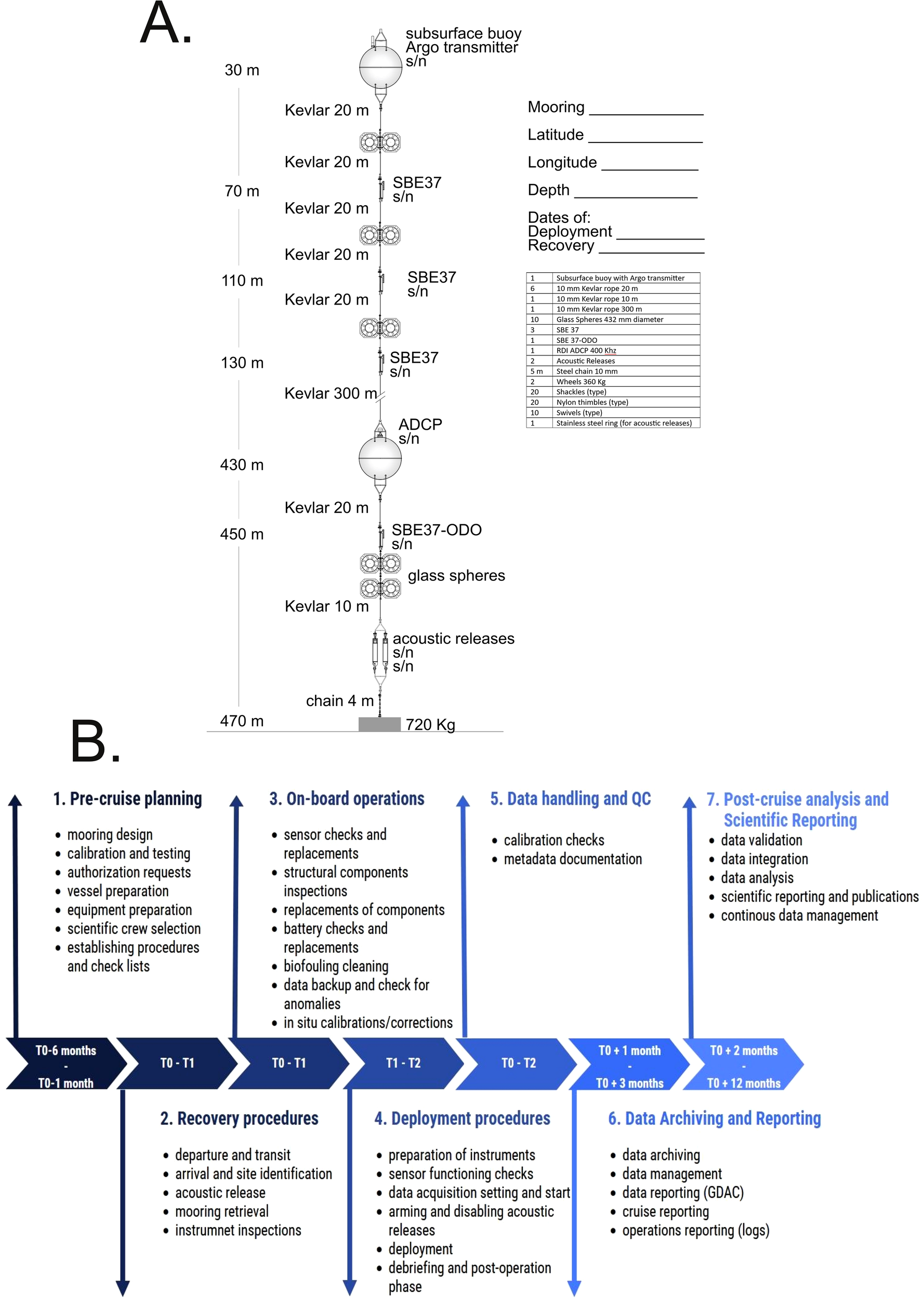
(A) Example showing which information should be contained in a mooring diagram; (B) visual timeline to follow for oceanographic mooring operations.
4.4 Stakeholders
Effective communication and coordination among all stakeholders involved in the mooring operations (Table 2) are essential to achieve the objectives of the FSP and contribute to oceanographic research.
Table 2
| Stakeholder | Role | Responsibilities |
|---|---|---|
| Principal Investigators (PI) | The Principal Investigator is central to the success of mooring operations. PIs define scientific objectives, data collection requirements, and research goals. PIs also provide strategic oversight and coordination. | PIs provide guidance on the deployment location, data variables of interest, and research priorities. They oversee the analysis of collected data for scientific insights. PIs oversee the integration of contributions from all stakeholders, ensuring that the mooring operations align with the established FSP. PIs are in charge of the successful implementation of the overall mooring system. |
| Technicians and engineers (TE) | Technicians and engineers are responsible for the set-up and the practical implementation of mooring operations, including mooring design, assembly, and maintenance. | They ensure the proper functioning of instruments, conduct maintenance, and troubleshoot technical issues during deployments and recoveries. |
| Vessel crews (VC) | Vessel crews operate the research vessel during mooring deployments, recoveries, and cruises. | Crew members handle vessel navigation, winch operations, safety protocols, and provide logistical support during fieldwork. |
| Data managers (DM) | Data managers oversee data handling, quality control, and archiving procedures. | They ensure data integrity, adherence to standards, and the timely submission of collected data to global data assembly centers (GDACs). |
| Environmental agencies and permit authorities (EA) | Environmental agencies and permit authorities grant permits for mooring deployments in accordance with international and local regulations. | They review deployment plans, assess environmental impact, and issue necessary permits for field operations. |
| Global Data Assembly Centers (GDACs) | GDACs serve as data repositories and hubs for global data exchange and integration. | They receive, archive, and disseminate collected data to the international scientific community, ensuring data accessibility and compliance with data standards. |
| External collaborators and partners (EC) | External collaborators and partners may include academic institutions, research organizations, or international initiatives. | They contribute to scientific research, provide resources, and collaborate on data analysis, furthering the scientific objectives of mooring operations. |
| Funding agencies (FA) | Funding agencies provide financial support for mooring operations and research projects. | They allocate resources, review project proposals, and monitor project progress to ensure funding alignment with research goals. |
| Regulatory bodies (RB) | Regulatory bodies may include national or international bodies overseeing oceanographic research. | They set and enforce regulations, standards, and compliance requirements for mooring operations. |
| Local communities and stakeholders (LC) | Local communities and stakeholders may be affected by mooring operations in coastal areas. | Engaging with local communities, providing information, and addressing concerns ensure positive relationships and local support. |
List of all stakeholders involved in the mooring operation and management, their role and responsibilities.
4.5 Timeline
Effective planning and execution of mooring operations within the FSP for SiCO require a well-defined timeline. This timeline consist of key milestones (Table 3), from pre-deployment planning to post-cruise data analysis, ensuring a structured and organized approach to the entire mooring operation (Figure 2B).
Table 3
| Phase | Start date | End date | Key persons |
|---|---|---|---|
| Pre-cruise planning phase: In this phase, detailed planning activities take place, including the definition of objectives, selection of deployment sites, mooring design, checking of equipment list and mooring diagram, instrument calibration, request of necessary permits and authorizations, shipping of equipment. | T0 – T180 | T0 – T30 | FA, PI, TE, VC, DM, RB & EA |
| Recovery Phase: At the end of a deployment period, the mooring is recovered from the deployment site. This phase involves vessel operations, winch or crane operations, careful handling of sensors and instruments, and data backup. | T0 | T1 | TE, PI, RB & VC |
| Post-recovery on-board operations phase: This phase includes routine maintenance, sensor checks, and monitoring of mooring functionality. Regular maintenance operations, including battery replacement, sensor calibration, and the replacement of sensors with recalibrated units, occur as needed. | T0 | T1 | TE & PI |
| Deployment phase: During the deployment phase, the mooring system is transported to the deployment site, sensors and instruments are secured to the mooring line, and deployment is executed. This phase involves vessel operations, mooring release mechanisms, and sensor installation. | T1 | T2 | TE, PI & VC |
| Data handling and quality control phase: During this phase, data collected during the deployment is reviewed and subjected to quality control checks. Data is flagged for anomalies, calibrated, and documented with accurate metadata. | T0 | T1 | TE, DM & GDAC |
| Data archiving and reporting phase: Data collected during the mooring operation is prepared for submission to designated Global Data Assembly Centres (GDACs). This phase includes data formatting, metadata compliance, and submission procedures. Comprehensive reporting and documentation of the mooring operation, including cruise reports, data quality reports, and metadata documentation, are finalized during this phase. | T0 + T30 | T0 + T90 | PI, DM, TE, EC & GDAC |
| Post-cruise analysis and scientific reporting phase: In the post-cruise phase, collected data is analyzed by scientists to derive scientific insights and achieve research objectives. Data integration and interpretation take place during this phase | T0 + T60 | T0 + T365 | PI, DM, EC & LC |
Timeline outlining the start and end dates for each phase of the mooring operation.
In defining Start and End Date we refer to T0 (time zero), which is the date of Recovery of the mooring (T1 corresponds to 1day after T0). The acronyms used for key persons are defined in Table 2.
By following this timeline, mooring operations within the FSP are systematically organized, ensuring that each phase is executed with precision and efficiency. This structured approach enhances the overall success of the mooring operation and contributes to the long-term monitoring of marine circulation in the Sicily Channel.
4.6 Pre-cruise planning
The success of the SiCO mooring system’s deployment begins with a thorough pre-cruise planning phase. This phase encompasses a range of activities and tasks that must be completed before the actual deployment of the mooring system. These preparations ensure the safe, efficient, and effective execution of the whole mooring system recovery, maintenance and re-deployment. The operations and steps outlined in Table 4 are undertaken during this phase. Some of them need to be performed only at the start of a long-term mission, such as the mooring design and assembly operations or the definition of the data management and quality control procedures.
Table 4
| Operation | Task | Description | Who |
|---|---|---|---|
| Mooring design and assembly | Mooring configuration | Define the specific configuration of the mooring system, considering the type of mooring (subsurface mooring), depth of deployment, and the placement of sensors and instruments. | PI, TE, EC & FA |
| Component selection | Select appropriate mooring components, including anchors, flotation devices, mooring lines (Kevlar or Dyneema fiber cables, i.e. high resistance at low diameters), and sensor housings, based on the deployment location and environmental conditions. | TE | |
| Instrument integration | Ensure that the sensors and instruments can be properly integrated into the mooring structure and securely fastened. Check maximum depth ranges. | TE | |
| Sensor calibration and testing | Sensor calibration | Conduct precise calibration of sensors, especially of Conductivity, Temperature, and Depth (CTD) probes, to ensure their accuracy and reliability during deployment period. | TE |
| Testing | Perform thorough testing of all sensors and instruments using adequate software to verify their functionality. Identify and address any issues or anomalies, and ensure that sensors are ready for deployment. | TE | |
| Obtaining necessary permits and authorizations | Regulatory review | Collaborate with relevant Italian and foreign authorities in the interested areas (environmental agencies and permit authorities) to review and obtain the necessary clearance for mooring deployments. | PI, RB & EA |
| Clearance application | Prepare and submit (6 months in advance) clearance applications, providing detailed information about the deployment plan, location, and potential environmental impact (also with the aim to obtain fishing bans and restrictions on other activities at the deployment site). | PI, RB & EA | |
| Vessel preparation | Vessel selection | Select an appropriate research vessel equipped with winch and crane systems, ensuring it meets the operational requirements for mooring deployments and recoveries. | PI & TE |
| Vessel inspection | Inspect all equipment, including winches, cranes, and other specialized tools, to confirm their functionality and readiness for deployment. | VC & TE | |
| Safety protocols | Establish safety protocols and measures to ensure the well-being of personnel involved in the deployment and on-board operations. | TE & VC | |
| Preparation of equipment and scientific crew | Equipment acquisition and preparation | Procure necessary materials, consumables, and spare parts for the deployment; organize the shipment of materials for deployment. | TE & PI |
| Shipping to port of departure | Ensure that the equipment is dry and in optimal condition; verify that all connector caps and closures are securely in place; implement proper packaging techniques for shipping. Oversee the shipping process to the designated port of departure. | TE & PI | |
| Scientific crew members selection and briefing | Compile a comprehensive list of scientific crew members and gather necessary documents, including IDs, training certifications, and insurance details. Assign to each member a number of specific tasks for the mooring maintenance cruise. Prepare a cabin arrangement plan, if required by captain. | PI | |
| Data management and quality control procedures | Data handling | Establish data handling procedures, including data logging, storage, and backup, to prevent data loss during deployment and recovery. | DM |
| Quality control protocols | Develop quality control procedures to monitor data and address any anomalies or issues that may arise. | DM | |
| Metadata documentation | Ensure comprehensive documentation of metadata, including deployment details, sensor specifications, and calibration records, to provide context for the collected data. | DM |
Key operations of the pre-cruise planning phase, their division into steps and the respective descriptions, along with key persons in charge.
The acronyms used for key persons are defined in Table 2.
4.7 Recovery Procedures
The recovery of the SiCO mooring system marks the conclusion of a deployment period, typically 6 months long. This section details the procedures involved in safely and effectively recovering the mooring (Table 5), ensuring the retrieval of data and the integrity of instruments.
Table 5
| Operation | Steps | Description | Who |
|---|---|---|---|
| Vessel departure and transit to the deployment site | Vessel mobilization | The research vessel designated for mooring deployment is mobilized, with all crew members (vessel crew and scientific crew) and equipment on board. | VC |
| Safety briefing | Prior to departure, a safety briefing is conducted, ensuring that all personnel are aware of safety protocols, emergency procedures, and the importance of adhering to safety regulations. | VC & PI | |
| Transit to mooring site | The vessel departs from its port of origin and navigates to the predetermined mooring site. | VC | |
| Contact with authorities | For Tunisian waters, reaching out to the Tunisian authorities 72h before arrival to destination is mandatory. Organize for embarking an observer, if requested. | PI & VC | |
| Vessel arrival at the recovery site | Navigation and positioning | The research vessel navigates to the precise recovery site, utilizing navigational charts and coordinates to reach the mooring’s location. | VC |
| Site identification | The recovery site is identified using GPS and acoustic positioning systems to ensure accuracy. | VC | |
| Embarkment of observer | Tunisian authorities sometime will meet us at the moorings’ location to bring an observer on board. | VC & RB | |
| Acoustic interrogation and release | Acoustic releases activation | Acoustic release systems are activated using specialized acoustic signals to trigger the release mechanisms of the mooring. | TE |
| Confirmation of release | Release command is sent and the successful release is received and verified through acoustic communication with the mooring system. | TE | |
| Waiting for surfacing | After release, the mooring system gradually rises to the surface. This phase calls for patience as it depends on the mooring’s depth and buoyancy. | TE, PI & VC | |
| Sighting surface buoys | Surface buoys attached to the mooring become visible as they approach the water’s surface. Visual sighting is essential for locating the position of the mooring head. In case of difficulties, rely on the satellite transmitter (if installed on the mooring head) which starts transmitting its position when at surface. This information is then sent via email to personnel in charge. | TE, PI & VC | |
| Approach and retrieval | The research vessel approaches the surfaced mooring buoys while maintaining a safe distance to prevent damage to the equipment. Crew members prepare and retrieve the surfaced mooring components with pickup poles and hooks. | VC | |
| Winch or crane operations for mooring retrieval | Equipment preparation | The winch or crane systems, depending on the vessel’s configuration, are prepared for mooring retrieval, ensuring that they are in good working order. | VC |
| Winch or crane operations | The winch or crane is engaged to initiate the retrieval process. Winch or crane operators carefully manage the ascent of the mooring, maintaining tension control to prevent sudden movements or equipment damage. | VC | |
| Handling of sensors and instruments | Instrument retrieval | As the crane retrieves the mooring, sensors and instruments are carefully recovered from the water. Handling procedures prioritize instrument protection to prevent damage or contamination. | VC & TE |
| Instrument inspections | Sensors, instruments and linking elements are inspected for any visible damage or issues. Any anomalies are documented for later evaluation. | TE |
Key operations of the recovery phase, their division into steps and the respective descriptions, along with key persons in charge.
The acronyms used for key persons are defined in Table 2.
By following these recovery procedures, the SiCO mooring system is retrieved safely, and valuable data collected during the deployment period are preserved for analysis, contributing to the scientific research in the Sicily Channel.
4.8 Post-recovery on-board operations
The on-board operations, after the recovery of all mooring components (with the exception of the anchors), including maintenance operations, are essential to ensure the continued functionality and reliability of the mooring and its associated sensors and instruments. This section outlines the specific activities that will be conducted during the post-recovery on-board operation phase (Table 6), and before the mooring system is re-deployed to start a new 6-monthly deployment period.
Table 6
| Operation | Steps | Description | Who |
|---|---|---|---|
| Routine sensor checks | Regular monitoring | Sensors and instruments are subject to routine checks to ensure their proper functioning. | TE |
| Calibration verification | Sensor calibration is verified to maintain data precision and accuracy. Calibration logs are reviewed to ensure adherence to calibration schedules. | TE | |
| Battery status assessment | To keep track of power levels, the status of batteries powering the mooring system, releases and sensors is assessed. | TE | |
| Scheduled battery changes | Batteries are replaced or recharged according to a predetermined schedule to prevent power failure during deployment. | TE | |
| Inspection of structural components | Visual inspection | Structural components of the mooring, including anchors, flotation devices, mooring lines, and linking elements (e.g., shackles, thimbles, and swivels) are visually inspected for signs of wear, corrosion, or damage. | TE |
| Mechanical integrity | The mechanical integrity of components is verified to ensure they can withstand environmental stresses and maintain mooring stability. Verify all frames, cables and connectors, checking for cuts, abrasions, cracks, and corrosion. Replace cables as needed, typically every 5 years. Worn but functional cables may be retained as spares. Prevent galvanic corrosion by using sacrificial anodes. | TE | |
| Structural repairs | Any identified structural issues (on e.g., wire, rope, floats, shackles, connectors, releases, hardware) are addressed with necessary repairs or component replacements to prevent mooring failure. E.g.: inspect sacrificial anodes and replace if at least 50% of the material is eroded; examine the housing for corrosion, removing sensors and clamps for cleaning and inspection; open the instrument if necessary; replace intact O-rings every 3-5 years using non-metallic tools; inspect, lubricate, or replace frequently accessed O-rings (e.g., those on the battery end cap); lubricate and reinstall hardware, ensuring proper instrument functionality; reassemble the instrument, replacing or reconditioning the desiccant bag. Verify functioning of the instrument after repairs and replacements. | TE | |
| Biofouling prevention and cleaning | Biofouling assessment | The mooring system and sensor surfaces are evaluated for biofouling, which may include the accumulation of marine organisms on sensor housings and equipment. | TE |
| Cleaning procedures | Biofouling is prevented or removed through cleaning procedures, which may include physical cleaning or anti-fouling coatings. For temperature and pressure sensors, fouling represents a minor issue: just maintain hydraulic system inlets and outlets, as well as pressure openings, free from debris. Conductivity and dissolved oxygen sensors are highly sensitive to both biological and non-biological fouling; reduce biological fouling with anti-fouling devices; rinse the conductivity cell with diluted Triton-X to prevent oil deposition as the cell crosses the sea surface. | TE | |
| Biofouling records | Records of biofouling assessments and cleaning activities are maintained for reference and trend analysis. | TE | |
| Data backup and storage | Data retrieval | Data collected during the deployment period are retrieved from sensors to onboard data storage systems, ensuring that no data are lost during the recovery process. | TE & PI |
| Data verification | The recovered data are verified for accuracy and completeness. Any discrepancies or anomalies are documented for further analysis. | TE & PI | |
| Flagging and addressing data anomalies | Anomalies detection | Identify and label anomalies and data points for further investigation. Flag data points deemed suspicious for review. | TE & PI |
| Investigation and resolution | Verify recovered data for accuracy and completeness, subjecting them to automated algorithms or manual inspection to detect anomalies or spikes indicating instrument malfunctions or environmental disturbances. Immediate investigations are conducted when flagged data are identified to determine the cause. If instrument malfunctions or data problems are confirmed, corrective action is taken. | TE & PI | |
| Backup and storage | Securely back up and store data to prevent loss or corruption. Maintain proper labelling and organization of data files to ensure accessibility and integrity. | TE & PI | |
| In-situ calibration and correction (options) | CTD cast at the mooring position | Conduct a CTD cast at the mooring point, comparing the collected data (at sensor nominal depths) with mooring data to ensure calibration accuracy. | PI |
| Cal-Dip cast | Attach mooring sensors to the rosette, perform a CTD cast while stationary for ten minutes at a fixed depth (avoiding vertical gradients), and then compare the data for offset detection. | TE | |
| Sample analysis | Close Niskin bottles during Cal-Dip or generic cast, collect seawater samples and analyze salinity and oxygen in the laboratory on board for comparison with mooring data, ensuring accurate in-situ calibration and correction. | TE |
Key operations of the post-recovery on board operations phase, their division into steps and the respective descriptions, along with key persons in charge.
The acronyms used for key persons are defined in Table 2.
4.9 Deployment procedures
The deployment of the SiCO mooring system is a critical phase in the FSP. This section outlines the step-by-step procedures involved in mooring deployment (Table 7), which is done after recovery and on-board maintenance operations, with the aim to start a new 6-months period of monitoring.
Table 7
| Operation | Steps | Description | Who |
|---|---|---|---|
| Preparation of all instruments for deployment | Checking the date and time in UTC | Ensure that the time and date are correctly set in UTC on all instruments and computers used during the deployment. | TE |
| Instrument memory check | Check that each instrument has sufficient storage space to handle the data during the entire planned measurement period. | TE | |
| Instrument log compilation | Document relevant activities, measurements and events for each instrument in a dedicated log, providing a detailed track of operations during deployment. | TE | |
| Activation of instruments and releases | Activate instruments by starting data acquisition (start data acquisition immediately or at a later date/time). Proceed with enabling the triggers to ensure a controlled release at the appropriate time. | TE | |
| Final pre-deployment checks | Pre-deployment checks | Before deployment, a thorough check of mooring release mechanisms of the acoustic release systems or other release mechanisms, is performed to ensure they are in good working conditions. | TE |
| Arming of releases | Upon reaching the designated deployment site, arm and enable the acoustic release devices. Put them in sleep mode to prevent battery consumption while disabled, ready to be activated from the surface during the subsequent recovery. | TE | |
| Deployment of sensors and instruments | Secure attachment of instruments | Securely attach sensors and instruments to the mooring structure, implementing additional safety fastenings for stability and ensuring the correct orientation for data collection. | TE |
| Winch operations | Sensors and instruments are deployed using winches or crane systems, with careful consideration of the depth at which they need to be positioned, following the defined mooring design and assembly scheme. | VC & TE | |
| Ship positioning and preparation for release | Position the vessel for release, passing the planned mooring position by at least the length corresponding to the depth of the bottom (500 m in this case); move the vessel to an appropriate distance from the release point (2-3 times the depth, i.e. approximately 1 nm); secure instruments to the mooring line as it is lowered into the sea, starting from the top elements and progressing downwards, while the vessel advances at the minimum steering speed towards the designated location. After deploying buoys and instruments overboard, retain only the acoustic releases and weights on board. | VC & TE | |
| Release of weights and acoustic releases | Just after passing the planned position, release the weights together with the acoustic release devices. Carefully observe the sinking of all floating elements. | VC & TE | |
| Marking the deployment position | Accurately mark the release point by taking geographical coordinates or using instruments on board the vessel. This act documents the exact location of the mooring on the seabed for future analysis and recovery. | TE | |
| Post operations procedures | Debriefing and documentation | Conduct a debriefing session after mooring recovery and re-deployment, gathering input from the crew to address any issues or lessons learned. Prepare comprehensive documentation of the recovery operation, ensuring a thorough record of the procedures undertaken. | PI, TE & VC |
| Data analysis | The recovered data are subject to further analysis as needed to derive scientific insights. | PI & TE | |
| Instrument maintenance | Instruments and sensors that required replacement, maintenance, calibration, or repairs are packed to be brought home, where appropriate actions will be taken to prepare them for future deployments. | TE |
Key operations of the deployment phase, their division into steps and the respective descriptions, along with key persons in charge.
The acronyms used for key persons are defined in Table 2.
4.10 Data handling and quality control
Effective data handling and quality control (Table 8) are integral to the success of the SiCO mooring system’s field service. This section outlines the protocols and procedures in place to ensure the integrity, accuracy, and reliability of collected data throughout the deployment period.
Table 8
| Operation | Steps | Description | Who |
|---|---|---|---|
| Calibration checks | Regular calibration | Sensors and instruments are periodically recalibrated to maintain data accuracy. The calibration schedules are strictly followed. | TE |
| Calibration logs | Detailed records of calibration activities, including dates, procedures, and calibration coefficients, are maintained for traceability. | TE | |
| Calibration verification | Calibration coefficients are applied during data processing to ensure that measurements are accurate and consistent. | TE | |
| Metadata documentation | Comprehensive metadata | Metadata, including deployment details, sensor specifications, and calibration records, are documented comprehensively to provide context for the collected data. | DM & TE |
| Metadata accessibility | Metadata are readily accessible and accompany data submissions to GDACs. | DM, TE & GDAC |
Key operations of the data handling and quality control phase, their division into steps and the respective descriptions, along with key persons in charge.
The acronyms used for key persons are defined in Table 2.
4.11 Data archiving and reporting
Effective data archiving, management, and reporting (Table 9) are crucial aspects of the SiCO mooring system’s field service. This section outlines the procedures and protocols for archiving and reporting data collected during the deployment period, ensuring accessibility, transparency, and the availability of data for scientific research and analysis.
Table 9
| Operation | Steps | Description | Who |
|---|---|---|---|
| Data archiving | Data storage | Data collected during the field service are stored securely on dedicated data storage systems onboard the research vessel and at the home lab. | DM & TE |
| Redundant backups | Multiple redundant backups of data are maintained to prevent data loss due to equipment failures or unforeseen circumstances. | DM & TE | |
| Data management | Data handling protocols | Comprehensive protocols are established for the handling, processing, and organization of data to ensure consistency and quality. | DM |
| Metadata documentation | Metadata, including deployment details, sensor specifications, calibration records, and quality control information, are documented alongside the data. | DM & TE | |
| Data accessibility | Data are made accessible to authorized personnel, researchers, and collaborators involved in the project. | DM, TE & EC | |
| Data format and metadata requirements | Data format | Prepare data for submission to designated GDACs. This phase encompasses post-processing activities (quality control, filtering, averaging, statistics, plots), data formatting, followed by metadata compliance, and submission procedures. Data are formatted in accordance with established standards and conventions. Standard data formats such as NetCDF or CSV may be used. | DM & GDAC |
| Metadata requirements | Metadata accompanying the data include, but are not limited to: deployment information (date, time, and geographic coordinates), sensor and instrument specifications (make, model, and calibration details), quality control information (flagging for anomalous data points), calibration records (coefficients and dates), data processing and quality control reports, information regarding any contingencies, deviations, or equipment malfunctions during data collection. This ensures comprehensive metadata accompanies the data, meeting the necessary requirements for archiving and reporting. |
DM & TE | |
| Data reporting and documentation | Data availability | Ensure data availability to the scientific community and research organizations through GDACs. This involves finalizing reports and documentation of the mooring operation (logs), including the cruise report and metadata documentation. | DM, GDAC & LC |
| Submission according to timelines | Data are reported and shared according to predetermined timelines. Semestral data submissions to GDACs are established to facilitate data exchange and integration with wider oceanographic research efforts. | DM, GDAC & LC | |
| Data DOI | Digital Object Identifiers (DOIs) or unique identifiers are assigned to the data, to enhance their discoverability and citation in scientific publications This step ensures that the data are not just available but also easily citable for research and analysis purposes. |
DM | |
| FAIR data principles | Data and metadata adhere to the FAIR (Findable, Accessible, Interoperable, and Reusable) data principles to ensure their discoverability, accessibility, and usability by the broader scientific community. | DM |
Key operations of the data archiving and reporting phase, their division into steps and the respective descriptions, along with key persons in charge.
The acronyms used for key persons are defined in Table 2.
4.12 Post-cruise analysis and scientific reporting
Post-cruise data analysis and scientific reporting (Table 10) ensures data validation, and integrating collected data into the overall dataset for scientific research and reporting.
Table 10
| Operation | Steps | Description | Who |
|---|---|---|---|
| Data validation | Data quality control | Data collected during the field service are subject to rigorous quality control checks. These checks include: validation of sensor and instrument calibration, identification and flagging of anomalous data points, verification of metadata consistency and completeness. | DM & PI |
| Data cleaning | Data are cleaned to remove outliers and data points flagged as anomalous during the field service. Any data gaps or missing information are addressed. | DM & PI | |
| Data integration | Data harmonization | Collected data are harmonized to ensure consistency in units, formats, and time stamps. Data from multiple sensors and instruments are integrated into a coherent dataset. | DM & PI |
| Spatial and temporal alignment | Data collected at different depths and times are aligned to create vertical profiles and time series, enhancing the dataset’s value for scientific analysis. | DM & PI | |
| Integration with historical data | The collected data are integrated with historical data from previous deployments, allowing for long-term trend analysis and comparison. | DM & PI | |
| Data analysis | Scientific analysis | Post-cruise data analysis involves scientific investigations, hypothesis testing, and research aimed at deriving significant insights from the dataset. | PI |
| Statistical analysis | Statistical methods are applied to assess variability, trends, and correlations within the dataset. | PI | |
| Reporting and publications | Scientific reporting | Results of post-cruise data analysis are documented in scientific reports, conference presentations, research papers, and publications. | PI |
| Collaboration | Collaboration with other research institutions and organizations is encouraged to promote knowledge sharing and collaborative research initiatives. | PI, LS & EC | |
| Continuous data management | Data updates | The dataset is regularly updated with newly collected data, ensuring that it is up to date and valuable for ongoing and future research. | PI & DM |
Key operations of the post-cruise data analysis and scientific reporting phase, their division into steps and the respective descriptions, along with key persons in charge.
The acronyms used for key persons are defined in Table 2.
4.13 Safety measures
Safety (Table 11) is of paramount importance throughout the field service of the SiCO mooring system. Comprehensive safety protocols and measures are in place to protect the well-being of all personnel involved, ensure the safety of the vessel crew, and safeguard equipment and the environment.
Table 11
| Operation | Steps | Description | Who |
|---|---|---|---|
| Safety briefings | Pre-deployment | Prior to each deployment or recovery operation, safety briefings are conducted. These briefings address potential hazards (e.g. weather/sea conditions), emergency procedures, and safety regulations. | TE, PI & VC |
| Regular updates | Safety protocols are reviewed and reinforced regularly to guarantee that all personnel are aware of their responsibilities and are up-to-date with safety procedures. | TE, PI & VC | |
| Equipment inspection and maintenance | Regular inspection | All equipment, including winches, cranes, sensors, and instrumentation, undergoes regular inspection to verify their operational integrity. | VC & TE |
| Maintenance | Routine maintenance and servicing of equipment are performed to prevent unexpected failures and ensure safe operation. | TE | |
| Personal Protective Equipment (PPE) | PPE requirements | Field personnel and vessel crew are required to wear appropriate PPE, including life jackets, helmets, gloves, and safety boots, to minimize personal risk. | PI & VC |
| Training | Personnel are trained in the proper use of PPE and their role in enhancing personal safety. | PI & VC | |
| Emergency response | Emergency drills | Regular emergency drills, such as man-overboard drills, fire drills, and abandon-ship drills, are conducted to prepare personnel for unexpected situations. | VC |
| Emergency contacts | Clear communication channels are established for emergency situations, including contact information for emergency services and medical facilities. | VC | |
| Environmental protection | Environmental regulations | Mooring operations adhere to environmental regulations and guidelines to minimize the impact on marine ecosystems and sensitive areas. | VC & PI |
| Spill response | Protocols for spill response and containment are in place to address accidental releases of pollutants. | VC & PI | |
| Adherence to local regulations | Regulatory compliance | All field operations are conducted in compliance with local regulations, permits, and authorizations. | VC & PI |
| Continuous training and awareness | Safety training | Personnel receive continuous safety training to stay informed about the latest safety procedures and regulations. | VC & PI |
| Safety culture | A safety culture is fostered, emphasizing the importance of vigilance, teamwork, and proactive hazard identification. | VC & PI | |
| Reporting and documentation | Incident reporting | Protocols are in place for personnel to report safety incidents, near misses, or concerns promptly. | VC |
| Documentation | Comprehensive safety records and incident reports are maintained for analysis and continuous improvement. | VC |
Key operations of the safety measures, their division into steps and the respective descriptions, along with key persons in charge.
The acronyms used for key persons are defined in Table 2.
These safety measures are integral to the SiCO mooring system’s field service operations, ensuring that the well-being of personnel and the protection of equipment and the environment are prioritized at all times. Strict safety protocols and fostering a safety-conscious culture ensures that the field service is conducted with the highest standards of safety and professionalism.
4.14 Contingency plans
Contingency plans (Table 12) are essential for anticipating and responding to unforeseen circumstances that may arise during the field service of the SiCO mooring system. These plans outline response procedures and considerations for addressing equipment malfunctions, adverse weather conditions, and emergency situations to ensure the safety of personnel and the success of the mission.
Table 12
| Circumstance | Response procedure | Who |
|---|---|---|
| Equipment malfunctions | In the event of equipment malfunctions or failures during deployment or recovery, field personnel and vessel crew are trained to follow established emergency shutdown procedures for the affected equipment. A designated technical expert or engineer is available on board to assess equipment issues and determine whether immediate repairs are feasible. If not, a decision is made on whether to continue with the operation or postpone it until the equipment is restored to working order. If equipment malfunctions jeopardize data collection or safety, the mooring system may need to be recovered and redeployed at a later time, following necessary repairs or replacements. |
TE & VC |
| Adverse weather conditions | Weather monitoring is conducted continuously throughout the operation. If adverse weather conditions are anticipated, including high winds, storms, or rough seas, the vessel captain and research team collaborate to make informed decisions regarding the safety of personnel and equipment. If adverse conditions arise during deployment or recovery, the operation may be temporarily halted or postponed until conditions improve, ensuring the safety of all involved. |
VC & PI |
| Regulatory authority directives | In the event that local or international authorities request the interruption or termination of field service operations in non-national waters, the following procedures will be followed: - Immediate compliance: the research vessel and field personnel will immediately comply with the directives and instructions provided by the relevant authorities. This may include ceasing all mooring deployment, recovery, or data collection activities. - Communication: the designated point of contact onboard the research vessel will establish clear and open communication with the authorities, acknowledging their instructions and seeking clarification if necessary. - Documentation: all instructions, communication, and directives received from the authorities will be thoroughly documented, including date, time, and any specific requirements or conditions imposed. - Safety and preparedness: field personnel will ensure that all equipment, including the mooring system, sensors, and data, is secured and prepared for interruption or termination of operations. - Cooperation: the research team will cooperate fully with authorities, providing any requested documentation, permits, or information to facilitate a smooth and lawful termination of activities. - Transition plan: depending on the circumstances, a transition plan may be developed in coordination with the authorities to safely conclude operations, secure equipment, and ensure environmental compliance. - Continuity and legal compliance: the research team will work closely with relevant legal counsel or representatives to ensure that all applicable laws, regulations, and permits are adhered to during the interruption or termination of operations. - Data protection: efforts will be made to protect and secure all collected data during the interruption period. Data storage, backup, and integrity will be a priority. - Communication with stakeholders: regular and transparent communication with stakeholders, including project managers, funding agencies, and research institutions, will be maintained to provide updates on the situation and actions taken. |
VC, PI, FA & RB |
| Recovery and resumption | Once authorities provide clearance and authorization for the resumption of field service operations, a detailed plan for recovery and resumption will be executed. This plan may include equipment checks, safety assessments, and coordination with relevant authorities to ensure a smooth transition back to full operation. | PI, VS & RB |
| Emergency situations | In the event of medical emergencies, accidents, or other life-threatening situations, emergency response protocols are followed, including immediate medical attention and evacuation procedures if necessary. Communication systems are maintained for rapid contact with emergency services and relevant authorities. | VC & PI |
| Reporting and documentation | All contingency events, responses, and decisions are thoroughly documented, including the rationale for any deviations from the original plan. Lessons learned from contingency situations are used to improve future field service plans and enhance safety protocols. | VC & PI |
List of circumstances requiring contingency planning, associated response procedures, along with key persons in charge.
The acronyms used for key persons are defined in Table 2.
By developing and following these contingency plans, the SiCO mooring system’s operations are better prepared to address unforeseen challenges while prioritizing the safety of personnel and the protection of data, equipment and the environment. These plans ensure a flexible and adaptive approach to field service operations while maintaining the highest standards of safety and professionalism.
4.15 Stakeholder communication
Effective communication with stakeholders (Table 13) is essential to ensure a successful field service operation and to keep all parties informed and engaged throughout the process. This section outlines the communication protocols for stakeholders, including regular updates, reporting of issues, and post-service debriefings.
Table 13
| Operation | Steps | Description | Who |
|---|---|---|---|
| Stakeholder identification | Primary stakeholders | Primary stakeholders include project managers, research institutions, funding agencies, and the scientific community involved in mooring operations and research. | PI |
| Secondary stakeholders | Secondary stakeholders may include local authorities, environmental organizations, and the broader public with an interest in the project. | PI | |
| Regular updates | Communication frequency | Regular updates are provided to stakeholders at predetermined intervals, such as weekly or as specified in project agreements. | PI, FA, LS & EC |
| Content of updates | Updates include information on the progress of the field service, data collection status, key milestones achieved, and any emerging issues or challenges. | PI, FA, LS & EC | |
| Communication channels | Updates are disseminated through various communication channels, including email, project websites, and designated stakeholder meetings. | PI, FA, LS & EC | |
| Issue reporting protocol | Stakeholders are provided with clear guidelines on how to report issues, anomalies, or concerns related to the field service. | PI, FA, LS & EC | |
| Post-service debriefings | Debriefing sessions | After the field service operation concludes, debriefing sessions may be conducted to gather feedback, lessons learned, and input from stakeholders. | PI, FA, TE, VC, LS & EC |
| Analysis and improvement | Feedback gathered during debriefings is analyzed to identify areas for improvement and to inform future field service planning. | PI, FA, TE, VC, LS & EC | |
| Contingency communication | Emergency communication | Clear communication protocols are established for emergency situations or unexpected events. Stakeholders are informed promptly in such cases. | PI, FA, TE, VC, LS & EC |
| Decision-making communication | In situations that require critical decisions, stakeholders are engaged in discussions and kept informed of decision outcomes. | PI, FA, TE, VC, LS & EC | |
| Public and media engagement | Public awareness | For projects with broader public interest, communication strategies for engaging the public and media are developed and implemented in compliance with relevant regulations and guidelines. | PI, FA, LS & EC |
| Transparency | Transparent communication is maintained with the public to provide accurate and balanced information about the project’s goals, progress, and impacts. | PI, FA, LS & EC | |
| Data sharing and collaboration | Data access | Stakeholders involved in research collaborations have access to project data as specified in data-sharing agreements. | PI, FA, LS & EC |
| Collaborative research | Collaboration and data sharing with research institutions and partners are encouraged to maximize the scientific value of the collected data. | PI, FA, LS & EC | |
| Documented Communications | Documentation | All stakeholder communications, including updates, issue reports, and meeting minutes, are documented for reference and record-keeping. | PI, FA, LS & EC |
Key operations of the communication with stakeholders, their division into steps and the respective descriptions, along with key persons in charge.
The acronyms used for key persons are defined in Table 2.
Effective stakeholder communication fosters transparency, trust, and collaboration among all parties involved in the mooring system field service. These communication protocols ensure that stakeholders are well-informed, engaged, and actively contribute to the success of the project.
4.16 Documentation
Comprehensive documentation of the FSP is diligently maintained throughout the project’s lifecycle. This documentation encompasses all revisions, reports, and any deviations from the plan that may occur during field operations. These records provide a historical record of the project’s evolution, ensuring transparency, accountability, and a valuable resource for future planning and analysis.
5 Discussion and conclusion
Oceanographic mooring operations are vital for advancing our understanding of the oceans, and their success is strongly centered around thorough planning and execution. This paper describes Field Service Plans (FSPs) in detail, highlighting their role in determining the outcomes of these missions. While we emphasize the FSP’s essential components, we also stress the need for FSPs to evolve alongside scientific progress, technological advancements, and environmental dynamics. The FSP’s timeline component provides structure to mission planning, streamlining operations, optimizing resource utilization, and minimizing downtime. Through the integration of safety protocols and contingency plans, FSPs foster a culture of safety among field personnel and crew, enhancing the well-being of all involved and mitigating the potential risks inherent to the open sea.
The FSP is designed as a useful guideline for the planning and execution of mooring operations, being a comprehensive strategy that ensures the reliability of data, and the success of missions in the marine environment. From the initial planning stages to post-cruise data analysis and scientific reporting, a well-structured FSP serves as a roadmap, ensuring that each step is executed with precision and purpose.
There are also a number of challenges in implementing FSPs. These include ensuring consistent adherence, incorporating evolving technology, enhancing interdisciplinary collaboration, and navigating budget constraints. Implementing an FSP across a diverse team of researchers and technicians can be challenging. To address this, it is useful to consider implementing training programs and workshops that familiarize team members with the FSP’s key components and emphasize its importance. Regular checks during field operations can help ensure that the FSP is being followed consistently, but also to ensure that the FSP is still up-to-date. As technology in oceanographic moorings evolves, FSPs may need to be updated. It could be useful to establish a protocol for technology integration within the FSP, like including a periodic review process to assess the compatibility of new technologies with the existing FSP framework. Finally, recognizing that budget constraints can limit the resources available for implementing the FSP, we advocate for a flexible budgeting approach. This includes the potential for collaboration with other research institutions and leveraging shared resources to optimize budget utilization, ensuring that the FSP can adapt to varying financial circumstances and maintain its effectiveness.
In essence, the challenges we encounter in implementing FSPs make it clear that these documents should not be set in stone but rather treated as living, evolving tools. The ever-changing nature of scientific research, technology, regulations, and environmental conditions demands that FSPs remain adaptable and responsive to new challenges and opportunities.
Each mooring system is unique, shaped by the demands of the scientific questions it seeks to answer and the environmental challenges it faces. This diversity underscores the need for adaptable and flexible planning tools. Our aim in sharing our FSP is to offer a starting point for a dialogue and a comparison with other systems, encouraging a collective advancement in the field.
Statements
Data availability statement
The original contributions presented in the study are included in the article/supplementary material. Further inquiries can be directed to the corresponding author.
Author contributions
KS: Conceptualization, Supervision, Visualization, Writing – original draft, Writing – review & editing. MB: Data curation, Investigation, Methodology, Validation, Writing – review & editing.
Funding
The author(s) declare financial support was received for the research, authorship, and/or publication of this article. The authors wish to acknowledge the fundings received through many national and European Projects (e.g. KM3NeT, EU GA #011937; SESAME, EU GA #GOCE-036949; PERSEUS, EU GA #287600; OCEAN-CERTAIN, EU GA #603773; COMMON SENSE, EU GA #228344; JERICO, EU GA #262584; JERICO-NEXT, EU GA #654410; JERICO S3, EU GA #871153; the Italian projects EMSO-Italia JRU and RITMARE, funded by the Italian Ministry of University and Research. This work was funded by the European Union under grant agreement no. 101094690 (EuroGO-SHIP).
Acknowledgments
The authors wish to acknowledge the collaboration and support received over many years of mooring operations in the Sicily Channel, by captains of Italian Research Vessels, their crew members, many colleagues and directors of CNR-ISMAR. The authors also acknowledge the HYDROCHANGES Programme of the Mediterranean Science Commission (CIESM) and the OceanSITES network (GOOS). Servicing has been done on board of the Italian R/Vs URANIA, MINERVA UNO, DALLAPORTA and GAIA BLU. The authors are deeply indebted to M. Astraldi and G.P. Gasparini, who initiated the mooring time series in the nineties, as well as to the captains and the crews for allowing the collection of these data.
Conflict of interest
The authors declare that the research was conducted in the absence of any commercial or financial relationships that could be construed as a potential conflict of interest.
The author(s) declared that they were an editorial board member of Frontiers, at the time of submission. This had no impact on the peer review process and the final decision.
Publisher’s note
All claims expressed in this article are solely those of the authors and do not necessarily represent those of their affiliated organizations, or those of the publisher, the editors and the reviewers. Any product that may be evaluated in this article, or claim that may be made by its manufacturer, is not guaranteed or endorsed by the publisher.
References
1
Coppola L. Ntoumas M. Bozzano R. Bensi M. Hartman S. E. Craig J. et al . (2016). Handbook of best practices for open ocean fixed observatories (European Commission). FixO3 Project, 127pp. (European Commission, FixO3 project, FP7 Programme 2007-2013 under grant agreement n° 312463. doi: 10.25607/OBP-1488
2
IOC (2019). Global ocean observing system: 2030 strategy (Paris: UNESCO). Available at: https://unesdoc.unesco.org/ark:/48223/pf0000368020.
3
Meindl A. (1996). Guide to moored buoys and other ocean data acquisition systems (Geneva, Switzerland: WMO & IOC, Data Buoy Cooperation Panel), 40pp. doi: 10.25607/OBP-1335
4
Ravaioli M. Bergami C. Riminucci F. Langone L. Cardin V. Di Sarra A. et al . (2016). The RITMARE Italian Fixed-Point Observatory Network (IFON) for marine environmental monitoring: a case study. J. Oper. Oceanogr.9, s202–s214. doi: 10.1080/1755876x.2015.1114806
5
Schroeder K. Chiggiato J. Josey S. A. Borghini M. Aracri S. Sparnocchia S . (2017). Rapid response to climate change in a marginal sea. Sci. Rep.7, 4065. doi: 10.1038/s41598-017-04455-5
6
Send U. Weller R. A. Wallace D. Chavez F. Lampitt R. Dickey T. et al . (2010). “OceanSITES,” in Proceedings of oceanObs’09: sustained ocean observations and information for society (Vol. 2) (ESA Publication WPP-306, Venice, Italy), 21–25. Available at: https://globalocean.noaa.gov/Research/Ocean-Reference-Stations-OceanSITES/.
7
Tanhua T. McCurdy A. Fischer A. Appeltans W. Bax N. Currie K. et al . (2019). What we have learned from the framework for ocean observing: evolution of the global ocean observing system. Front. Mar. Sci.6. doi: 10.3389/fmars.2019.00471
8
Venkatesan R. Ramesh K. Kishor A. Vedachalam N. Atmanand M. A. (2018). Best practices for the ocean moored observatories. Front. Mar. Sci.5. doi: 10.3389/fmars.2018.00469
9
Weller R. A. Baker D. J. Glackin M. M. Roberts S. J. Schmitt R. W. Twigg E. S. et al . (2019). The challenge of sustaining ocean observations. Front. Mar. Sci.6, 105. doi: 10.3389/fmars.2019.00105
Summary
Keywords
oceanographic moorings, field service plan (FSP), mooring operations, data management, safety protocols
Citation
Schroeder K and Borghini M (2024) An example of a field service plan for oceanographic submerged moorings. Front. Mar. Sci. 11:1380914. doi: 10.3389/fmars.2024.1380914
Received
02 February 2024
Accepted
27 September 2024
Published
23 October 2024
Volume
11 - 2024
Edited by
Virginie Van Dongen-vogels, Australian Institute of Marine Science (AIMS), Australia
Reviewed by
Christoph Waldmann, University of Bremen, Germany
Natalie Robinson, National Institute of Water and Atmospheric Research (NIWA), New Zealand
Mark Doubell, South Australian Research and Development Institute, Australia
Updates
Copyright
© 2024 Schroeder and Borghini.
This is an open-access article distributed under the terms of the Creative Commons Attribution License (CC BY). The use, distribution or reproduction in other forums is permitted, provided the original author(s) and the copyright owner(s) are credited and that the original publication in this journal is cited, in accordance with accepted academic practice. No use, distribution or reproduction is permitted which does not comply with these terms.
*Correspondence: Katrin Schroeder, katrin.schroeder@cnr.it
Disclaimer
All claims expressed in this article are solely those of the authors and do not necessarily represent those of their affiliated organizations, or those of the publisher, the editors and the reviewers. Any product that may be evaluated in this article or claim that may be made by its manufacturer is not guaranteed or endorsed by the publisher.