Abstract
Offshore wind turbines (OWTs) often operate in complex marine environments, where they are not only subjected to wind and wave loads, but also adversely affected by scour. Therefore, it is of great significance to explore the effect of scour on the dynamic responses of OWTs under external loads to ensure structural safety, improve performance, and extend service life. In this study, a comprehensive numerical model of a 5-MW OWT, including tower, monopile, and soil-structure interaction (SSI) systems, is established by using ABAQUS platform. Aerodynamic loads is generated using blade element momentum, while wave loads is generated using the P-M spectral. The depth of scour is obtained based on on-site measured data. A comparative analysis is conducted between fixed foundations and SSI systems when conducting dynamic response analysis of OWTs under wave loads. Subsequently, the effect of scour on dynamic responses of OWTs under aerodynamic and wave loads is investigated. Results demonstrate that SSI can significantly influence the natural frequency and dynamic responses of the OWT. Therefore, it is essential to thoroughly consider SSI when evaluating the dynamic response of the OWT with local scour. The tower-top displacement and acceleration of the OWT with show a significant increasing trend compared to the non-scoured OWT. An increase in scour depth leads to higher maximum stress and stress amplitude in the steel monopile, which could potentially cause fatigue issues and should be given due attention.
1 Introduction
The operating environment of OWTs is more complex than that of onshore wind power structures, with higher technical requirements. The long-term harsh service environment makes OWTs more prone to damage under complex loading conditions. OWTs are inevitably affected by various natural disasters during service, among which scour, wind, wave loads are the most common disaster causing factors. The scour reduces the soil cover around the pile, changes the stiffness and boundary conditions of the pile foundation, and causes irreversible changes in its dynamic characteristics under aerodynamic and wave loads, posing significant risks to the safe operation of OWTs.
Offshore wind energy has the characteristics of abundant resources, high wind speed, low turbulence intensity, no land occupation, and few restrictions on wind farm construction. Pile-supported structure as a key load-bearing component of OWTs, accounts for 20% to 25% of the total cost and is an important part of the design process of OWTs (Keivanpour et al., 2017). Under local scour, scour pits will form near the monopile foundation, leading to a decrease in the horizontal bearing capacity of the foundation and affecting the normal operation of OWTs (Qi and Gao, 2016). Therefore, considering the local scour effect becomes particularly important for the design of the support structure. The support structure of OWTs is subjected to simultaneous loads from wind, waves, and currents, resulting in significant overturning moments at the mud surface position. Under the simultaneous action of currents and waves, there is usually scour at the seabed position, forming scour pits near the support structure, reducing the insertion depth of the foundation, thereby reducing its horizontal bearing capacity and affecting the normal operation of OWTs.
For the problem of local scour of a cylinder under uniform flow, Sumer et al. (Sumer et al., 1992) found, based on the research of Breusers et al. (Breusers et al., 1977), that the average equilibrium scour depth of a vertical cylinder under uniform flow conditions is 1.3D, with a variance of 0.7D, and the local scour is independent of the Re number, where Re = UD/υ, U is the average flow velocity at depth, D is the diameter of the cylinder, υ is the viscosity coefficient of fluid motion. Regarding the problem of local scour of vertical cylinders under wave action, Sumer et al. (Sumer et al., 1992) and Kobayashi and Oda (1994) found that the equilibrium scour depth is closely related to the wave KC number. Local scour only occurs when KC ≥6, where KC = UmT/D, where Um is the velocity amplitude of wave water point movement, and T is the wave period. This is mainly because vortex shedding occurs behind the pile at this time, and the horseshoe vortex in front can be fully developed. The maximum depth of local scour of a vertical cylinder under the combined action of waves and currents is relatively complex. In addition to being affected by the KC number, it is also related to the ratio of uniform flow velocity Uc to the amplitude of wave water quality point velocity Um (Sumer and Fredsøe, 2001). The above research work has given people a profound understanding of the local scour problem of underwater vertical cylinders. However, the above empirical prediction formulas are mostly established on the basis of loose and uniform sand physical experiments, and cannot consider the common transport characteristics of cohesive soil in engineering sea areas. Therefore, it is difficult to directly apply them to the scour prediction of prototype pile foundations. In summary, scour is influenced by multiple factors, and the current method to obtain accurate scour depth is still on-site measurement. Therefore, this study will use on-site scour measurement data of wind turbine foundations in wind farms to analyze the dynamic response of OWTs.
In addition, many researchers have also analyzed the impact of local scour on the dynamic response of structures under external environmental loads. Ma et al (Ma et al., 2018). applied finite element method to study the effect of scour on the structural response of triangular OWTs. Tseng et al (Tseng et al., 2017). studied the deformation response of monopile foundations under scour by modifying the soil resistance pile deformation (p-y) curve around the pile. Qi et al (Qi et al., 2016). conducted a series of centrifuge model tests with different scour profiles to investigate the effects of local and general scour on the response of laterally loaded piles. The study introduced the concept of effective soil depth to determine the corresponding p-y curves for shallowly buried piles in sand, which serves as a practical method for assessing the impact of scour. Li et al. (Biao et al., 2024) performed a comprehensive finite element analysis to explore the effects of scour on lateral pile-soil interaction. They quantified how the slope angle of scour pits affects the lateral response of pile foundations using the effective soil depth method. Their study refined the formula for evaluating the impact of scour on p-y curves and extended its application to any slope angle of scour pits. Liu et al. (Liu et al., 2016) conducted local scour experiments on the foundation structures of monopile OWTs with different diameters, studying the relationship between the size of scour pits and the depth of scour. Bush et al. (Bush et al., 2009) studied the influence of foundation on the structural response of OWTs based on their consideration of aerodynamic characteristics. Jun et al. (Jung et al., 2015) applied the finite element method to calculate the top load response curve of the foundation, and simulated the influence of the foundation on the structural response of OWTs by solving the foundation stiffness matrix. Hansen et al. (Hansen et al., 2007) studied the variation law of scour through actual measurements. Li et al. (Li et al., 2014) used data obtained from on-site monitoring and numerical simulation to obtain the dynamic response law of OWTs under different water depths and wave loads. Kim et al. (Kim et al., 2014) conducted a refined simulation of OWTs by establishing spring elements to simulate pile-soil interactions. Takehiko and Takeshi (2014) conducted a series of studies on OWTs in service to investigate the load combination effects when they encounter earthquakes during operation. He (2015) studied the effects of depth, width, and slope angle of scouring pits on the horizontal bearing capacity of pile foundations. Hu et al. (Hu et al., 2015) studied the horizontal bearing capacity of a monopile under different scouring conditions, and obtained the influence of scouring and the fixing method of the pile top on the bearing capacity of a monopile. Zha et al. (Zha et al., 2023) innovatively applied the hyperplastic ratcheting model to a aero-hydro-servo-elastic simulation tool, considering the changes in stiffness, damping, and accumulated displacement of monopile OWTs under cyclic loading. The research provides an accurate model for estimating the fatigue life of monopile OWTs. Zha et al. (Zha et al., 2022) proposed a simplified model with two cyclic loading factors to accurately predict the accumulated displacement of monopiles. This model effectively predicts the accumulated displacement of monopiles in soft clay. The research findings provide a new method for design codes to accurately estimate monopile displacements. In summary, the analysis of the impact of scour on the dynamic responses of monopile foundations or OWT support structures is relatively extensive. However, studies evaluating the effects of actual scour depth on the dynamic response of OWTs under aerodynamic and wave loads are still relatively rare.
The monopile-supported OWT will inevitably be affected by foundation scour caused by seabed currents and wave impact at the sea surface. The soil surrounding the pile will gradually erode, creating an increasingly larger scour pit, which poses a significant threat to the overall structural safety of the OWT under aerodynamic and wave loads. Therefore, ensuring the safety and stability of the OWT under foundation scour and external loads is particularly important. Based on the above analysis, the study first simulates the aerodynamic loads on the blades using the blade element momentum theory. Next, wave loads are simulated in the time domain using the P-M wave spectrum. Subsequently, a complete finite element model of the OWT, including the tower, monopile foundation, and SSI system, is established using the ABAQUS platform. Aerodynamic and wave loads are synchronously applied to the OWT model for dynamic response calculation. Finally, the impact of different scour depths on the dynamic response of the OWT under external loads is analyzed. The results of this study provide a theoretical basis for the engineering design, construction, and safety assessment of OWTs.
2 Establishment of structural model of OWTs
2.1 5-MW OWT and monopile
The National Renewable Energy Laboratory (NREL) 5-MW OWT has been used in a number of wind energy projects. Monopile is a foundation structure commonly used to support wind turbines in offshore locations. It consists of a single steel pile that is driven into the seabed, upon which the wind turbine is mounted. The monopile-supported OWT used in this study is illustrated in Figure 1, which also defines the coordinate system, where x, y and z represent the heave, fore-after and side-to-side direction of the OWT, respectively. Table 1 shows the parameter properties of NREL 5-MW wind turbine.
Figure 1
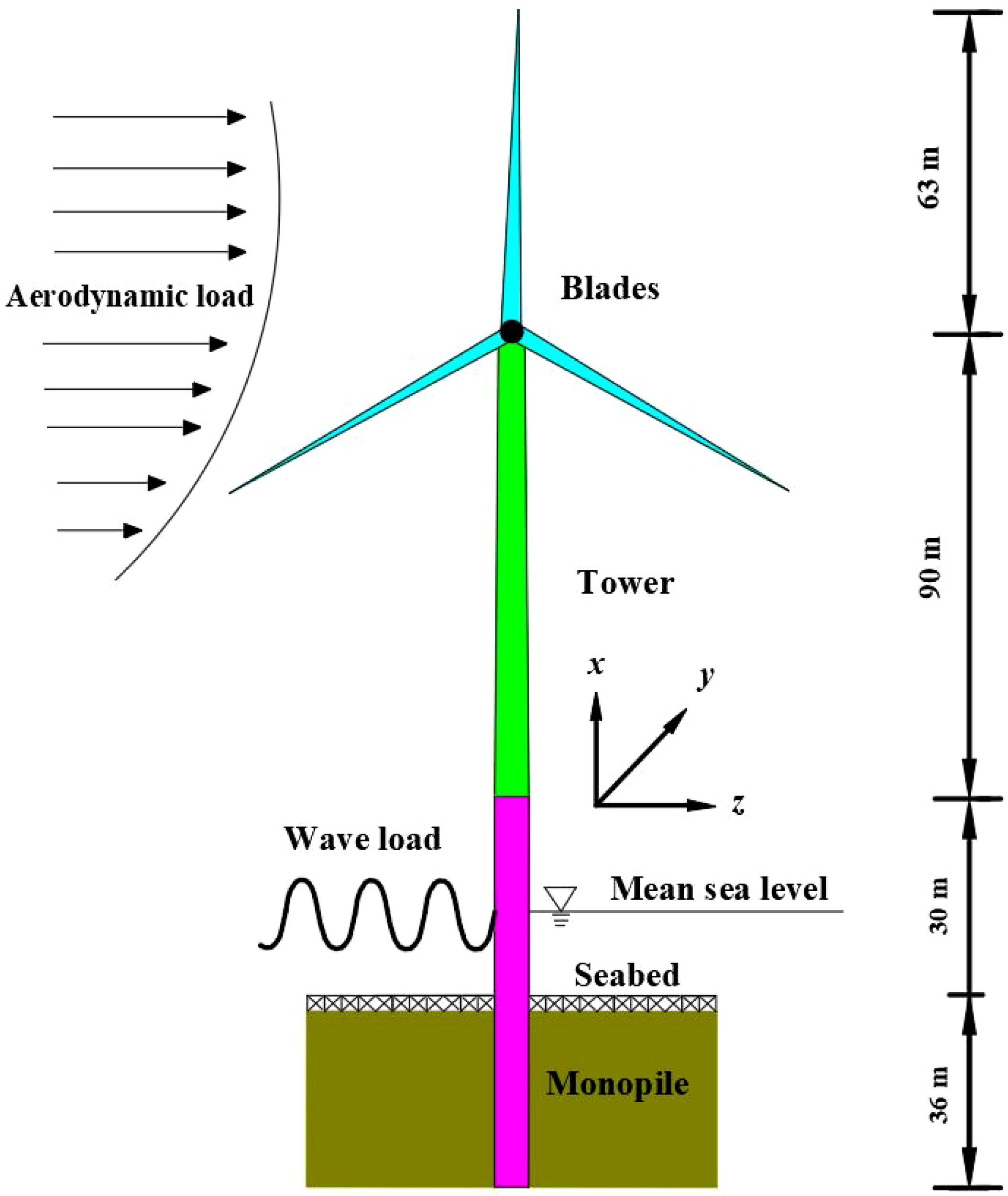
NREL 5-MW OWT and monopile foundation.
Table 1
| Component part | Parameter | Value |
|---|---|---|
| Blade | Rotor orientation, configuration, diameter | Upwind, 3 blades, 126 m |
| Hub height | 90 m | |
| Cut-in, rated, cut-out wind speed | 3 m/s, 11.4 m/s, 25 m/s | |
| Overall (integrated) mass | 17,740 kg | |
| Hub and Nacelle | Hub diameter | 3 m |
| Hub mass | 56,780 kg | |
| Nacelle mass | 240,000 kg | |
| Tower | Height above water | 90 m |
| Overall (integrated) mass | 347,460 kg | |
| Monopile | Diameter | 6.0 m |
| Length below the seabed | 36.0 m | |
| Total length | 66.0 m |
Parameter properties of NREL 5-MW wind turbine and monopile (Jonkman et al., 2009).
A finite element model of the monopile OWT was established using ABAQUS. The tower model and the monopile model above the mudline were constructed using the shell element (ABAQUS: S4 elements). The monopile model below the mudline was established using the beam element (ABAQUS: B31 element) to facilitate the application of nonlinear soil springs to consider the influence of soil-structure interaction (SSI). Rotor-Nacelle Assembly (RNA) mass is assumed as a lumped mass attached on the top of the tower. To uphold deformation continuity at the junction between the tower and the monopile, the cross sections of the tower-bottom and the monopile-top are tied. A unit mesh size of 1 meter along the tower and monopile of the OWT is proven adequate for achieving accurate simulations.
The total damping of OWTs mainly includes contributions from the aerodynamic damping, hydrodynamic damping, structural damping, and soil damping. The aerodynamic damping given in the literature varies between 2% and 8% (Hansen et al., 2006; Koukoura et al., 2015). In this study, aerodynamic damping is simulated by placing dampers on the top of the tower of the OWT (Schafhirt and Muskulus, 2018). The aerodynamic damping of 3.5% is considered in this study as suggested in Kuhn (2001). In this study, a constant Rayleigh damping equivalent to a damping ratio of 2% of critical damping is utilized, which consists of 1% structural damping, 0.2% hydrodynamic damping, and 0.8% soil damping. The similar choice has been utilized by several other authors (Carswell et al., 2015; Damgaard et al., 2015).
In this study, the fundamental frequency of the monopile OWT with SSI is 0.243 Hz, which is between 1P and 3P recommended in (DNV-OS-J101, 2014). The natural frequencies of the monopile OWT without and with SSI are presented in Table 2. From the Table 2, it can be observed that there is a significant difference in the vibration mode of the OWT between fixed foundation and considering SSI, which also reflects the significant impact of SSI on the vibration characteristics of the OWT. In addition, it can be seen that the first few natural frequencies of the OWT established in this study are consistent with those obtained by Yang et al. (Yang et al., 2019), which verifies the reliability of the OWT model.
Table 2
| Mode | Description | Fixed | SSI | SSI in (Yang et al., 2019) |
|---|---|---|---|---|
| 1 | 1st order OWT fore-aft mode | 0.264 | 0.243 | 0.249 |
| 2 | 1st order OWT side-side mode | 0.260 | 0.239 | 0.248 |
| 3 | 2nd order OWT fore-aft mode | 1.937 | 1.512 | 1.534 |
| 4 | 2nd order OWT side-side mode | 1.417 | 1.368 | 1.383 |
The natural frequencies of the monopile OWT without and with SSI.
2.2 Soil-structure interaction
The p-y method can better reflect the deformation characteristics of pile-soil interaction, especially in describing the nonlinearity of pile-soil interaction. Compared with other linear simulation methods such as K method and m method, it is more reasonable. This is because the p-y method considers the nonlinear effects of soil, rather than just treating it as an elastic body. The p-y method can more accurately predict the response of piles under horizontal loads by simulating the relationship curve between the horizontal reaction of the soil at a certain depth below the mudline and the deflection of the pile at that point.
The p-y method is utilized to simulate SSI. This study calculates the soil spring parameters based on the soil layer information provided in (Passon, 2006), and all soil layers are made of sandy soil, as shown in Table 3. This study utilized the nonlinear p-y curves obtained based on the LPILE platform under cyclic loads (Passon, 2006). The p-y curves used in this study are shown in Figure 2.
Table 3
| Depth below the seabed | Soil layer | Saturated unit weight γsat | Angle of friction ϕ |
|---|---|---|---|
| 0~5 m | Layer 1 | 10.0 kN/m3 | 33.0° |
| 5~14 m | Layer 2 | 10.0 kN/m3 | 35.0° |
| 14~36 m | Layer 3 | 10.0 kN/m3 | 38.5° |
Soil condition used in this study (Passon, 2006).
Figure 2
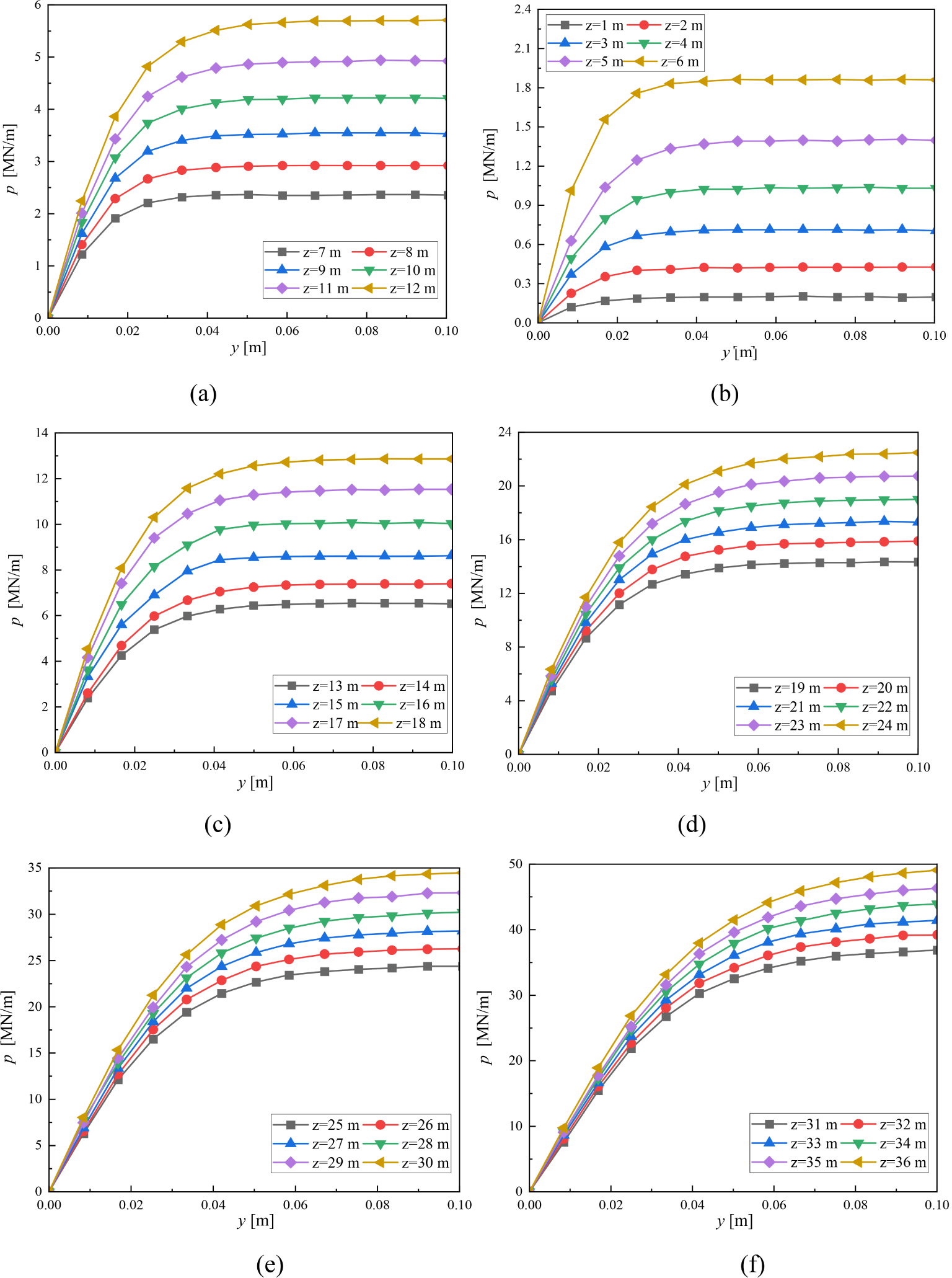
The p-y curves at different depths: (A) z=1~6 m; (B) z=7~12 m; (C) z=13~18 m; (D) z=19~24 m; (E) z=25~30 m; (F) z=31~36 m.
2.3 Scour depth
The depth of scour is influenced by various factors, and the scour mechanism is also very complex. The waves, currents, tides, and other factors in the marine environment are one of the main factors affecting the depth of scour. Strong winds, waves, and high tides can increase the impact of the marine environment on the foundation, leading to deeper scour depths. In addition, the shape, material, size, and other characteristics of the foundation structure can affect the depth of scour. For example, flat bottomed foundations may be more susceptible to scour compared to columnar foundations because they provide a larger surface area in contact with water flow, thereby increasing the likelihood of scour. The type, density, stability, and other characteristics of seabed soil can also affect the depth of scour. Soft seabed soil may be more susceptible to scour, resulting in deeper scour depths, while hard seabed soil is relatively less susceptible to scour. The depth of scour gradually accumulates over time. Basic structures exposed to the marine environment for a long time will be subjected to continuous scour, resulting in a gradual increase in scour depth.
On site measurement is one of the most accurate methods for evaluating the depth of scour. By regularly inspecting and measuring the foundation structure in actual marine environments, it is possible to directly observe and record changes in scour depth. This method can take into account the actual situation of the marine environment and the actual state of the infrastructure, and has high accuracy and reliability.
Therefore, this study will use the on-site scouring and scanning results of a wind turbine foundation in a certain offshore wind farm as a theoretical analysis basis to conduct dynamic response analysis of OWTs under scouring conditions. Figure 3 shows a three-dimensional monitoring diagram of wind turbine foundation scour in a certain offshore wind farm. Table 4 presents the measured results of wind turbine foundation scour in a certain offshore wind farm. In order to investigate the impact of scour depth on the overall dynamic performance of OWTs, this study conducted a detailed analysis of a scour depth of 7.38 m.
Figure 3
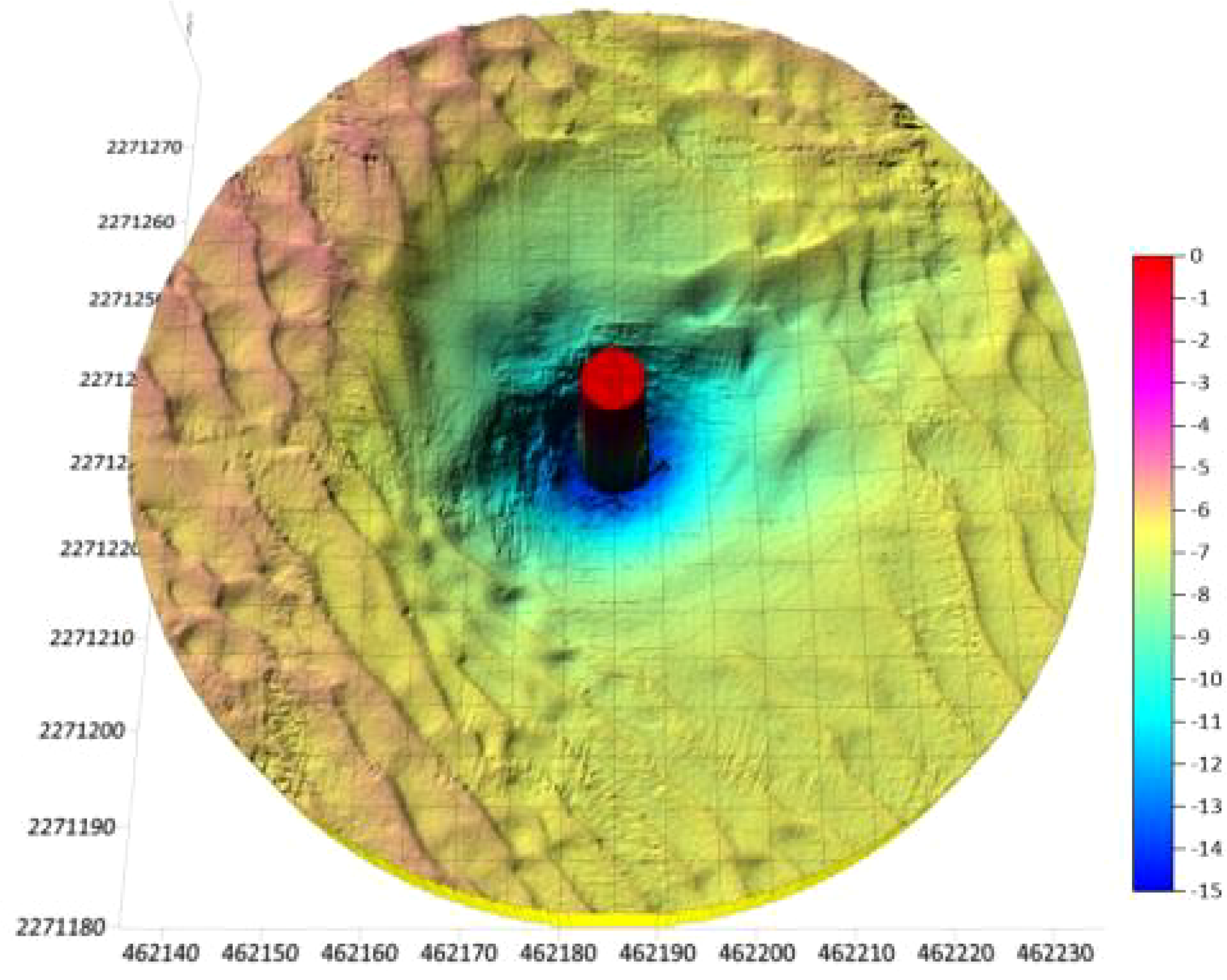
Three dimensional monitoring diagram of OWT foundation scour in a certain offshore wind farm.
Table 4
| Monopile diameter [m] | Pile sinking date | Monitoring date | Scour depth [m] | Scour volume [m3] |
|---|---|---|---|---|
| 6.0 | 2020/08/25 | 2022/03/06 | 7.38 | 3380 |
Actual measurement results of wind turbine foundation scour in a certain offshore wind farm.
3 External loads
3.1 Aerodynamic loads
The model based on the logarithmic law of wind speed variation was established and expressed as follows:
where Vh and Vhr represent mean wind speeds, h represents elevation, hr represents reference height, and h0 represents roughness parameter.
The Kaimal spectrum (Burton et al., 2001) was utilized to obtain frequency components, which can be expressed as:
where f denotes cyclic frequency, Lk represents integral length, and σ is standard deviation.
The Blade Element Momentum (BEM) theory was applied to calculate aerodynamic loads on blades, with lift force FL perpendicular to relative flow direction and drag force FD parallel to it. FL and FD per unit length can be calculated using lift and drag coefficients CL and CD, blade chord length c, and relative wind speed Vrel.
The wind loads time history on the blades is simulated based on the FAST platform, with an average wind speed of 11.4 m/s selected for the hub height. Due to the fact that this study only considers the dynamic effects in the Fore-Aft direction, only the wind force Fx and bending moment My are given, as shown in Figure 4.
Figure 4
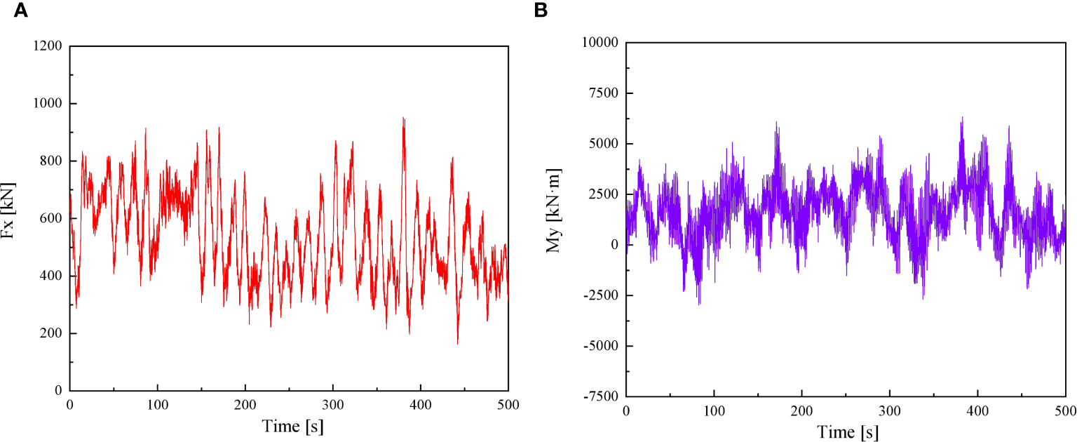
Time history of equivalent loads acting on blades. (A) Wind load 227 Fx; (B) Bending moment My.
3.2 Wave loads
Pierson and Moskowitz (1963) proposed a formula for an energy spectrum distribution of wind-generated sea wave in 1963. This spectrum, commonly referred to as the P-M model, has been widely adopted by ocean engineers and stands as one of the most representative spectra in waters worldwide.
The P-M spectrum model characterizes a fully developed ocean, determined by a single parameter: wind speed. Both fetch and duration are considered infinite. Applicability of this model necessitates prolonged, near-constant wind speeds over large areas for many hours before wave data acquisition, with minimal variations in wind direction. Despite these assumptions, the P-M model finds numerous applications in the design of marine structures.
The P-M spectrum model can be expressed as:
where 0.0081. Alternatively, in term of the frequency of spectral peak:
The variance of the wave elevation () or the zeroth moment (m0) is defined as the area under the spectral curve:
If we substitute :
If we substitute for ,
Also, the root square water surface elevation, , is related to the peak frequency as:
Noting that
The peak frequency is related to the significant wave height by
An equivalent expression for the P-M spectrum in terms of the cyclic frequency, f may be expressed as:
where .
To perform the generation of sample functions of the wave load process according to Equations 5–15, which take advantage of the classical fast Fourier transforms, the upper cutoff frequency is taken as 50 Hz and the global period is taken as 500 s. Two random sample functions based on the P-M wave spectral model are generated. One of them is generated at the significant wave height of 3.5 m and the peak spectral period of 5.4 s. The other one is generated at the significant wave height of 6.3 m and the peak spectral period of 9.0 s. The wave parameters used in this study are presented in Table 5. The time series of two wave loads are displayed in Figure 5 for the entire period 500 s in order to better visualize the differences and similarities among the generated time histories.
Table 5
| Wave case | Return period | Significant wave height | Peak spectral period |
|---|---|---|---|
| W1 | 1 year | 3.5 m | 5.4 s |
| W2 | 50 years | 6.3 m | 9.0 s |
Wave parameters used in this study.
Figure 5
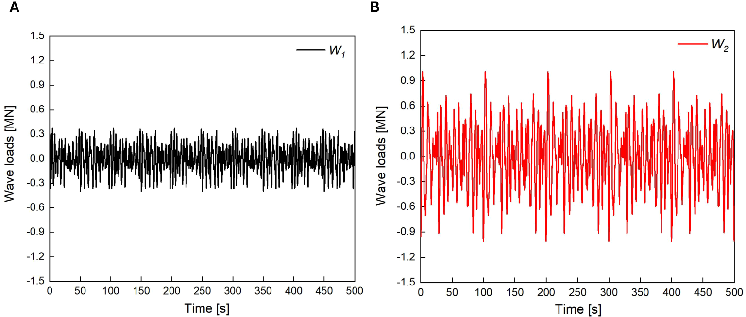
The time series of two wave conditions used in this study. (A)W1 wave 272 loads; (B)W2 wave loads.
4 Result analysis
4.1 The effect of SSI
The mode analysis results of the OWT using fixed foundation and considering SSI are shown in Figure 6. For brevity, the first two order normalized Fore-Aft modal shapes along elevation above mudline. The first-order natural frequencies of the OWT with fixed foundation and considering SSI are 0.264 Hz and 0.243 Hz, respectively. It can be observed that SSI has a significant impact on the natural frequency of the OWT.
Figure 6
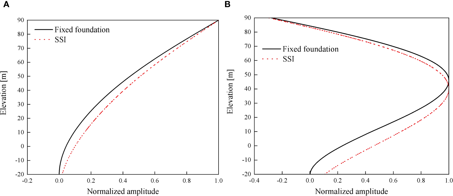
The first two order normalized modal shapes of the OWT above mudline (scour depth=0 m). (A) 1st order Fore-Aft mode; (B) 2nd order Fore-Aft mode.
In addition, this section of the study mainly considers the impact of SSI on dynamic behaviour of the OWT. 500 seconds wave load time series is applied to the OWT for dynamic response calculation. In this part of the examples, the scouring effect was not considered, which means that the scouring depth is 0 m. Figures 7 and 8 show the displacement time histories of the tower-top of the OWT under W1 and W2 wave loads, respectively. As shown in Figures 7 and 8, the tower-top displacement of the OWT considering SSI shows a significant increasing trend compared to the tower-top displacement of the OWT under fixed foundation. In addition, it can be observed that as the wave load increases, this displacement amplification trend becomes more pronounced. Table 6 lists the maximum displacement at the tower-top of the OWT. As shown in Table 6, when the OWT is subjected to wave loads W1 and W2, the maximum displacement at the tower-top of the OWT considering SSI is 0.114 m and 0.180 m, respectively. Compared with the maximum displacement of 0.062 m and 0.107 m without SSI, it increases by 83.9% and 68.2%, respectively.
Figure 7
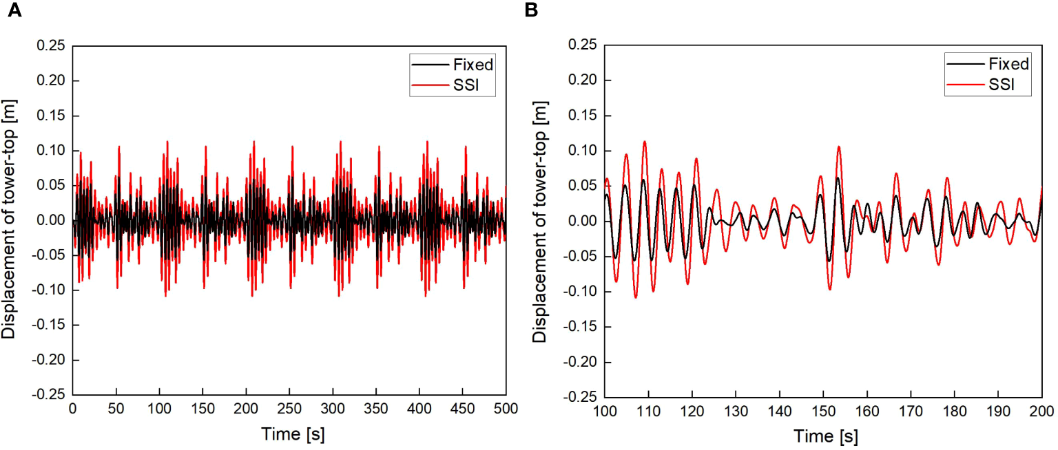
Displacement of tower-top with and without SSI under W1 wave loads (scour depth=0 m) (A) 0~500 s; (B) 100~200 s.
Figure 8
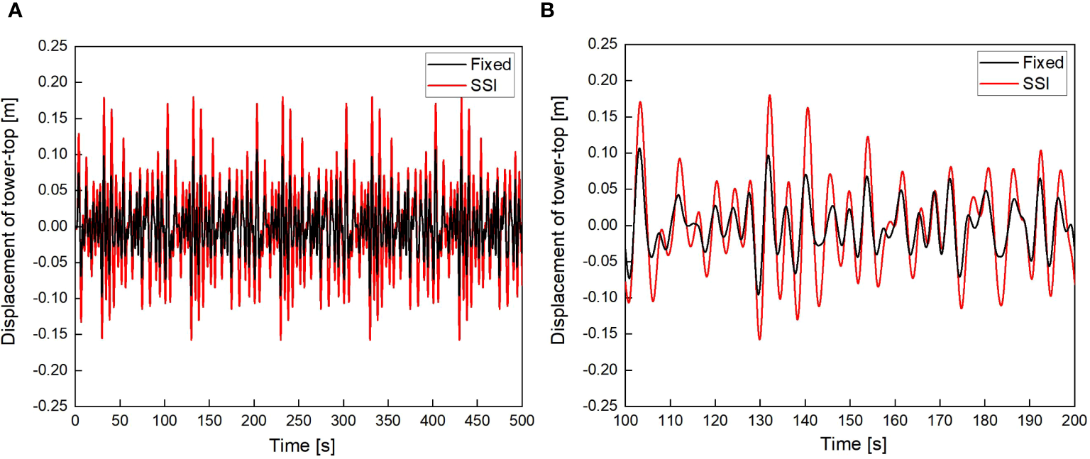
Displacement of tower-top with and without SSI under W2 wave loads (scour depth=0 m). (A) 0~500 s; (B) 100~200 s.
Table 6
| Wave load | Maximum displacement (m) | Maximum acceleration (m/s2) | ||
|---|---|---|---|---|
| Fixed | SSI | Fixed | SSI | |
| W1 | 0.062 | 0.114 | 0.162 | 0.279 |
| W2 | 0.107 | 0.180 | 0.196 | 0.338 |
Maximum of tower-top dynamic responses with and without SSI (scour depth=0 m).
Figures 9 and 10 show the acceleration time histories of the tower-top of the OWT under W1 wave loads and W2 wave loads, respectively. As shown in Figures 9 and 10, the acceleration at the tower-top of the OWT considering SSI is significantly higher than that without SSI. As the wave load increases, the acceleration at the tower-top also gradually increases. Table 6 lists the maximum acceleration at the tower-top of the OWT. As shown in Table 6, when the OWT is subjected to W1 wave loads and W2 wave loads, the maximum accelerations at the tower-top of the OWT considering SSI are 0.279 m/s2 and 0.338 m/s2, respectively. Compared with the maximum accelerations of 0.162 m/s2 and 0.196 m/s2 without SSI, the maximum accelerations increase by 72.2% and 72.4%, respectively. From the above analysis, it can be concluded that SSI has a significant impact on tower-top displacement and acceleration. Therefore, it is crucial to fully consider the impact of SSI on the dynamic response of the OWT.
Figure 9
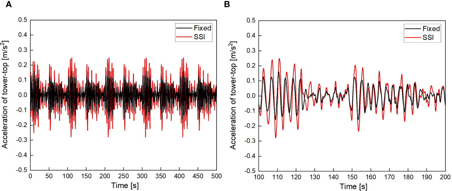
Acceleration of tower-top with and without SSI under W1 wave loads (scour depth=0 m). (A)t = 0~500 s; (B)t = 100~200 s.
Figure 10
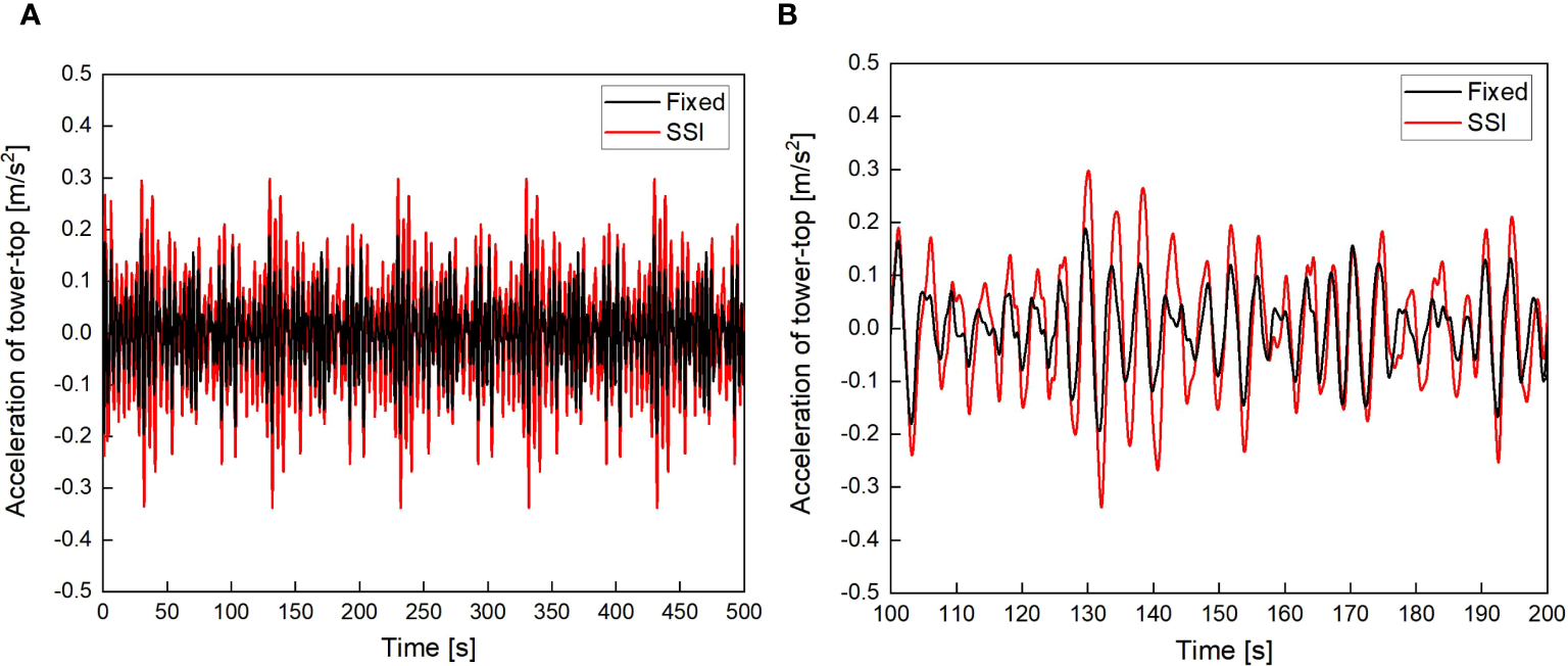
Acceleration of tower-top with and without SSI under W2 wave loads (scour depth=0 m). (A)t = 0~500 s; (B)t = 100~200 s.
4.2 The effect of local scour
After discussing the impact of SSI in Sec. 4.1, this section will use W2 wave load as input to discuss the impact of local scour on the dynamic response of the OWT under wave and aerodynamic loads. And the dynamic response analysis parameters were studied using tower-top displacement and bending stress at the mudline, revealing the influence of scouring on the dynamic response of the OWT. It should be noted that the following calculation conditions all consider SSI. In order to study the impact of scour depth on the overall dynamic performance of the OWT, this study used the measured scour depth of 7.38 m as the calculation basis for scour depth. 500 seconds aerodynamic and wave loads time series are applied to the OWT for dynamic response calculation. In order to eliminate instantaneous interference caused by load application, the calculation results for the first 10 seconds are not displayed.
Figure 11 shows the time-history of displacement of the tower-top with and without scour under aerodynamic and wave loads. As shown in Figure 8, the tower-top displacement of the OWT with scour under wave and aerodynamic loads is significantly greater than that of the non-scour state. Due to the influence of aerodynamic loads, the random fluctuations of the OWT’s tower-top displacement are more pronounced and exhibit reciprocating motion on one side of the equilibrium position. This results in greater magnitude and fluctuation amplitude compared to the displacement of the OWT under wave loads alone. Figure 12 shows the frequency domain results of tower-top displacement with and without scour under aerodynamic and wave loads. It can be seen that compared to the original non-scouring state, the vibration frequency of the OWT after scouring is lower, so the vibration mode excited under aerodynamic-wave loads is lower. In addition, the amplitude of the scoured OWT at the characteristic frequency is greater than the structural amplitude of the original non-scouring state, indicating that the scoured OWT has a higher energy content under load excitation, which in turn leads to a larger dynamic response of the OWT.
Figure 11
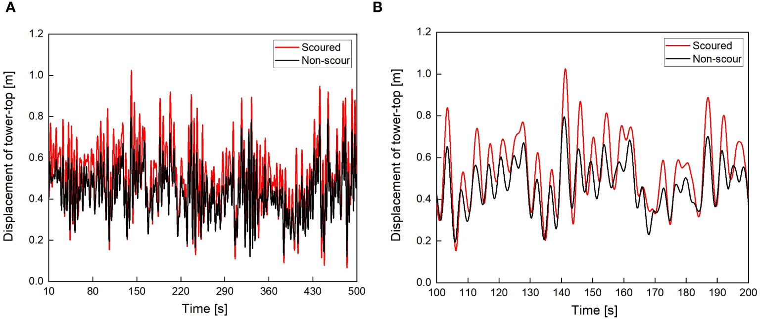
Tower-top displacement of the OWT with and without scour under aerodynamic and wave loads. (A)t = 10~500 s; (B)t = 100~200 s.
Figure 12
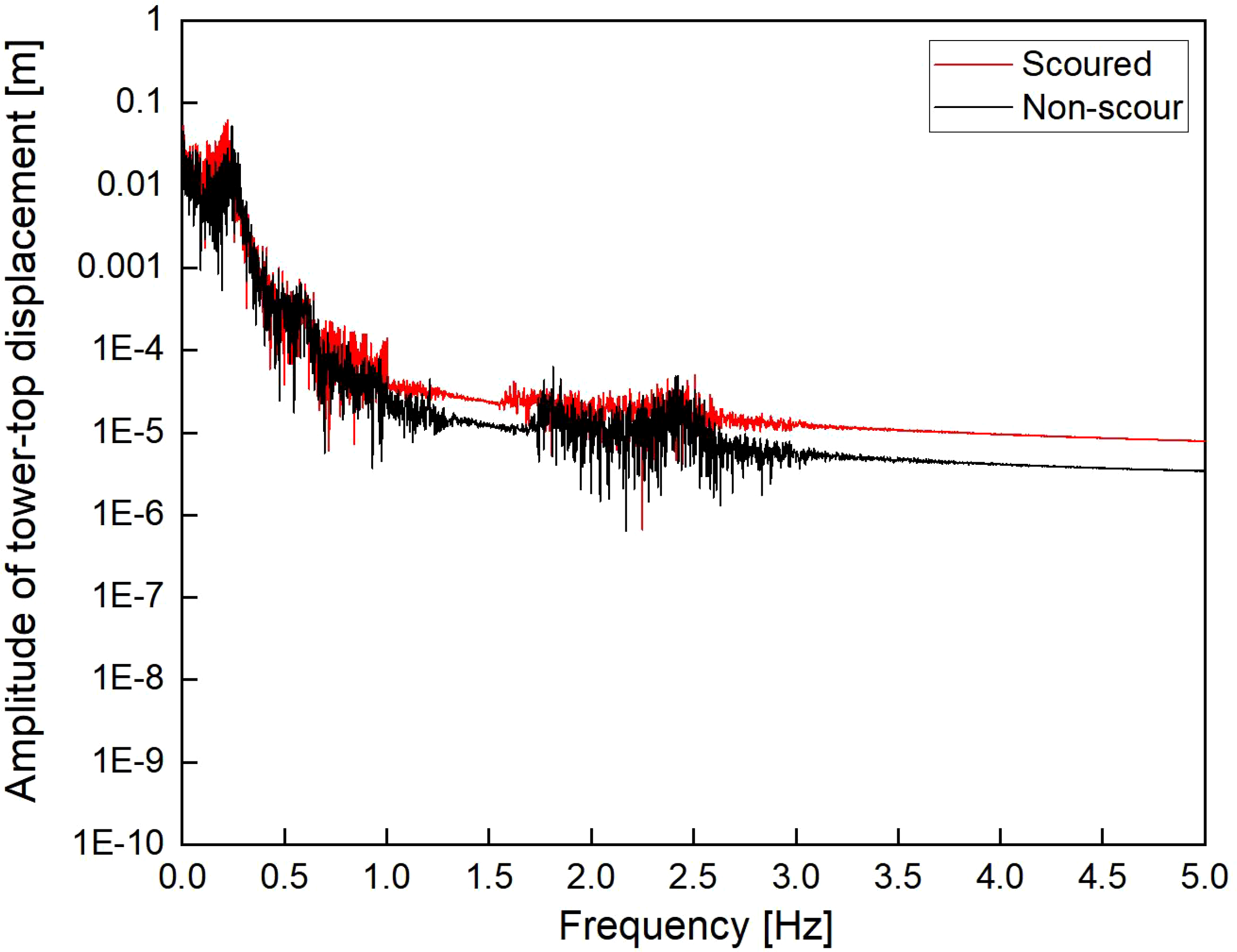
Frequency domain results of tower-top displacement with and without scour under aerodynamic and wave loads.
Figure 13 shows the statistic of tower-top displacement with and without scour under wave loads or combined aerodynamic-wave loads. It can be observed from Figure 13A that the maximum displacement at the tower-top of the OWT under combined aerodynamic and wave loads is significantly greater than under wave loads alone. For instance, the maximum displacement of the OWT without scour under combined loads is 0.795 m, which is 341.7% higher compared to the maximum displacement of the OWT without scour under wave loads alone. Figure 13B shows a similar trend for the standard deviation of displacement, indicating that the displacement variability of the OWT under combined aerodynamic and wave loads is much larger than under wave loads alone. Thus, it is evident that the OWT experiences more severe vibrations in operational conditions (wave and aerodynamic loads) compared to its parked state (wave load only). Additionally, scour increases both the maximum displacement and the standard deviation of displacement for the OWT. For example, the maximum displacement and standard deviation of the scour-affected OWT are 1.024 m and 0.161 m under the combined effects of aerodynamic and wave loads, respectively. These values are 28.8% and 34.2% higher than those of the OWT without scour under the same loads. This indicates that scour significantly amplifies the dynamic response of the OWT under external loads, which is highly detrimental to its operational stability and safety.
Figure 13
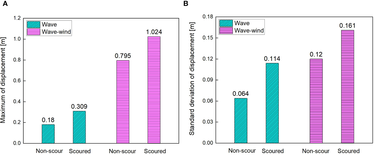
Statistic of tower-top displacement with and without scour under wave loads or combined aerodynamic-wave loads. (A) Maximum; (B) Standard deviation.
The bending stress of monopile at the mudline of the OWT under aerodynamic and wave loads are obtained. The stress calculation points (A, B, C, D) of the monopile cross-section are shown in Figure 14. Figure 15 shows the bending stress of mudline position without scour under aerodynamic and wave loads. It can be found that the stress amplitude range at points A and C is higher than at points B and D. This phenomenon is due to the fact that external loads are directly applied along the A-C line on the cross-section, while the B-D line coincides with the neutral axis of the section. Consequently, the stress cycles at points A and C are significantly higher than those at points B and D.
Figure 14
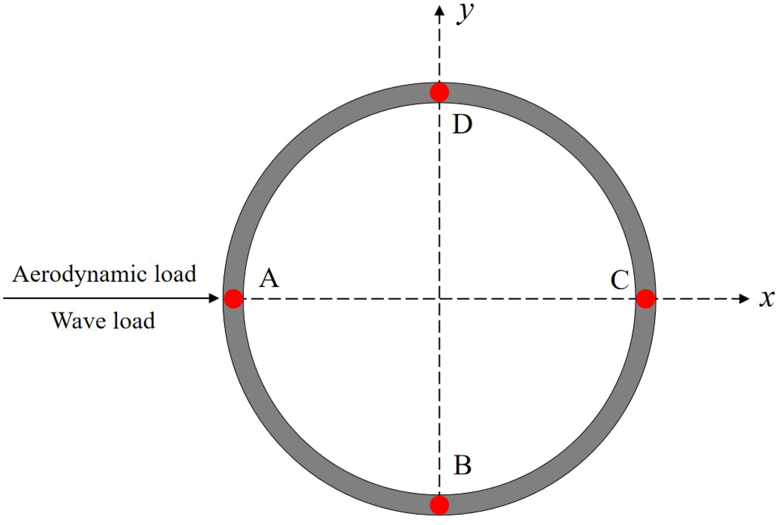
Stress points distributed along the cross-section of the monopole.
Figure 15
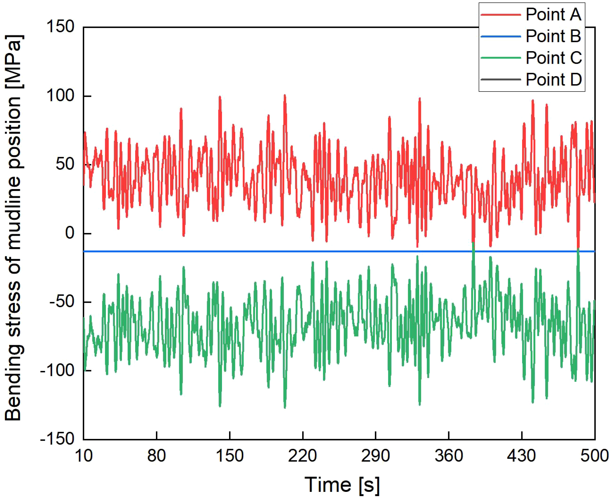
Bending stress of mudline position without scour under aerodynamic and wave loads.
Figure 16 shows the time history of bending stress at the mudline of the OWT with and without scour under wave and aerodynamic loads. As shown in Figure 16, the bending stress at the mudline of the OWT with scour under wave and aerodynamic loads is slightly greater than that in the original non-scouring state. This is because scour increases the length of the monopile shaft in the water, which expands the unconstrained range of the monopile foundation and makes the OWT as a whole more flexible. Consequently, the stress on the scoured OWT is higher compared to the non-scoured OWT under aerodynamic and wave loads.
Figure 16
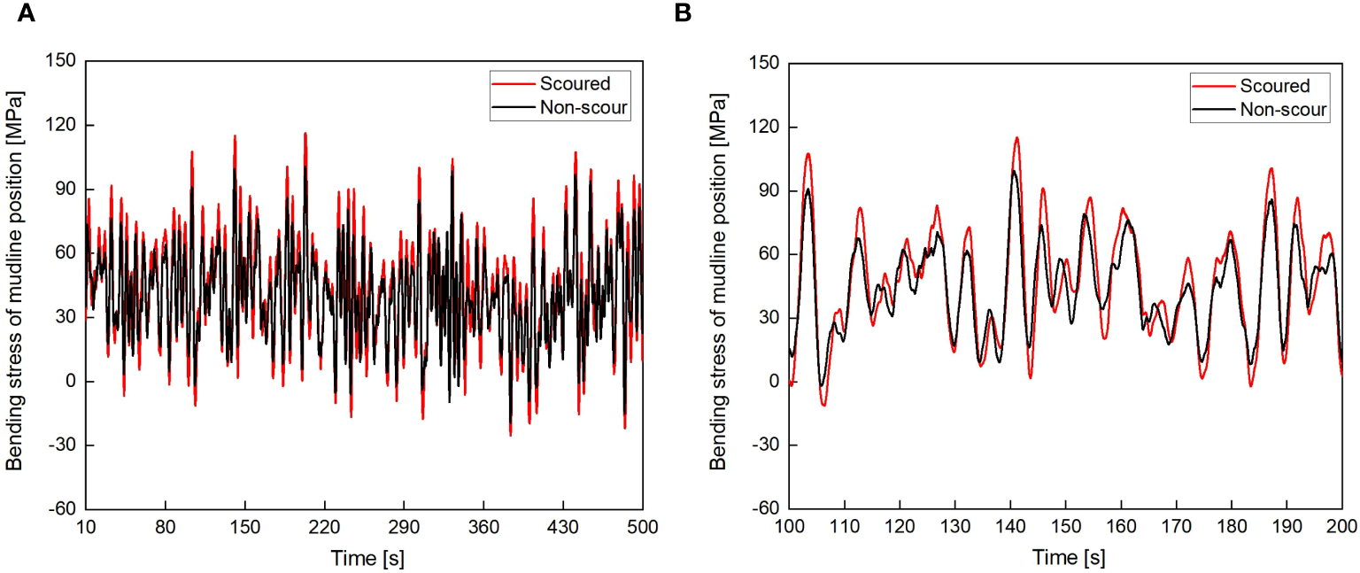
Bending stress of point A with and without scour under aerodynamic and wave loads. (A)t = 10~500 s; (B)t = 100~200 s.
Figure 17 shows the statistic of bending stress of mudline position with and without scour under wave loads or combined aerodynamic-wave loads. It can be observed that the maximum stress on the OWT under combined aerodynamic and wave loads is significantly greater than under wave loads alone. For instance, the maximum stress of the OWT with non-scour under combined loads is 100.583 MPa, which is 222.3% higher than the stress value under wave loads alone. Due to the significant increase in the length of the monopile located in the water under scour, the limiting effect of the soil around the monopile is reduced compared to the original non-scouring state, resulting in a decrease in the overall stiffness of the OWT. The stress level and amplitude of OWT under aerodynamic and wave loads are relatively high, which has a negative impact on the fatigue cumulative damage of OWT.
Figure 17
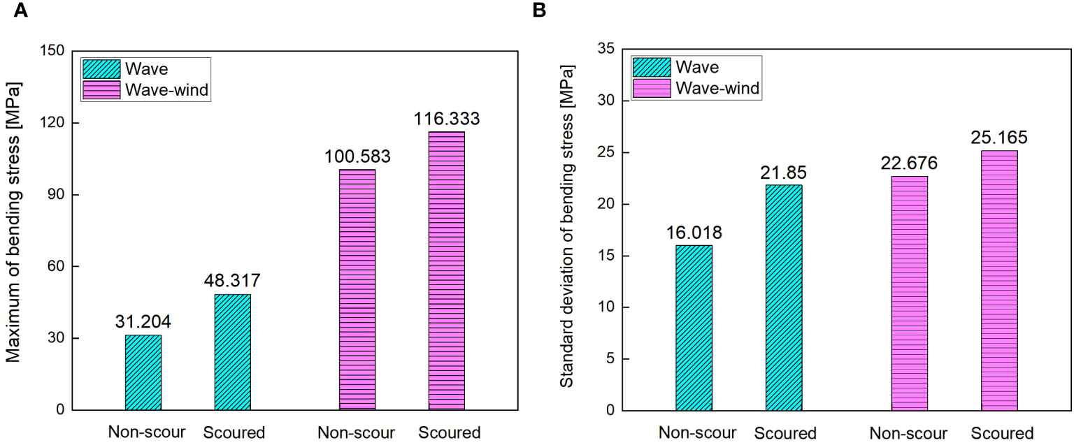
Statistic of bending stress of mudline position with and without scour under wave loads or combined aerodynamic-wave loads. (A) Maximum; (B) Standard deviation.
5 Conclusion
The scouring effect poses a serious challenge to the dynamic behavior of the pile-supported OWT. Especially under complex marine environmental loads, the stability and safety of the OWT after scour should be given more attention. Based on the calculation results obtained from this study, the following main conclusions have been summarized:
-
The tower-top displacement and acceleration of the OWT considering SSI show a significant increasing trend compared to those under fixed foundations. In addition, it can be observed that as the wave load increases, this amplification trend becomes more pronounced. SSI has a significant impact on tower-top displacement and acceleration. Therefore, it is crucial to fully consider the impact of SSI on the dynamic response of OWT.
-
The tower-top displacement response of the OWT after scour under wave and aerodynamic loads is significantly greater than that of the original non-scouring state. Compared with the original non-scouring state, the vibration frequency of the scoured OWT is lower, resulting in lower vibration modes excited under wind-wave loads.
-
The amplitude of the OWT after scour at the characteristic frequency is greater than that of the original structure without scour, indicating that the OWT after scour has a higher energy content under load excitation, which in turn leads to a larger dynamic response of the OWT.
-
Due to the significant increase in the length of the pile located in the water under scour, the limiting effect of the soil around the pile is reduced compared to the original non-scouring state, resulting in a decrease in the overall stiffness of the OWT. Under wind-wave excitation, the stress level and amplitude of the OWT are higher, which has an adverse effect on the fatigue accumulation damage of the OWT.
Statements
Data availability statement
The original contributions presented in the study are included in the article/supplementary material. Further inquiries can be directed to the corresponding author.
Author contributions
YY: Methodology, Project administration, Writing – original draft. MR: Conceptualization, Investigation, Software, Writing – original draft. CY: Data curation, Formal Analysis, Validation, Writing – review & editing. ZW: Resources, Software, Visualization, Writing – original draft. CZ: Investigation, Project administration, Supervision, Writing – original draft. TW: Methodology, Software, Writing – review & editing.
Funding
The author(s) declare that financial support was received for the research, authorship, and/or publication of this article. This work was financially supported by the Key-Area Research and Development Program of Guangdong Province (Grant No. 2022B0101100001) and the National Natural Science Foundation of China (Grant No. 52201313) and the Fundamental Research Funds for the Central Universities (Grant No. DUT22RC(3)091).
Conflict of interest
Authors YY, MR, CY, ZW were employed by the company Guangdong Energy Group Science and Technology Research Institute CO. LTD.
The remaining authors declare that the research was conducted in the absence of any commercial or financial relationships that could be construed as a potential conflict of interest.
Publisher’s note
All claims expressed in this article are solely those of the authors and do not necessarily represent those of their affiliated organizations, or those of the publisher, the editors and the reviewers. Any product that may be evaluated in this article, or claim that may be made by its manufacturer, is not guaranteed or endorsed by the publisher.
References
1
Biao L. Wen-Gang Q. Yifa W. Fu-Ping G. Shun-Yi W. (2024). Scour-induced unloading effects on lateral response of large-diameter monopiles in dense sand. Comput. Geotechnics174, 106635. doi: 10.1016/j.compgeo.2024.106635
2
Breusers H. N. C. Nicollet G. Shen H. W. (1977). Local scour around cylindrical piles. J. hydraulic Res.15, 211–252. doi: 10.1080/00221687709499645
3
Burton T. Sharpe D. Jenkins N. Bossanyi E. (2001). Wind energy handbook (Ltd. Print ISBN: 9780471489979: John Wiley and Sons). doi: 10.1002/0470846062
4
Bush E. Agarwal P. Manuel L. (2009). “The Influence of foundation modeling assumptions on long- term load prediction for OWTs,” in International Conference on Offshore Mechanics and Arctic Engineering (Honolulu, Hawaii, USA).
5
Carswell W. Johansson J. Løvholt F. Arwade S. R. Madshus C. DeGroot D. J. et al . (2015). Foundation damping and the dynamics of offshore wind turbine monopiles. Renew. Energ.80, 724–736. doi: 10.1016/j.renene.2015.02.058
6
Damgaard M. Andersen L. V. Ibsen L. B. (2015). Dynamic response sensitivity of an offshore wind turbine for varying subsoil conditions. Ocean Eng.101, 227–234. doi: 10.1016/j.oceaneng.2015.04.039
7
DNV-OS-J101 (2014). Design of offshore wind turbine structures (Høvik, Norway: Det Norske Veritas).
8
Hansen E. A. Simonsen H. J. Nielsen A. W. Pedersen J. Høgedal M. (2007). “Scour protection around offshore wind turbine foundations, full-scale measurements,” in Scientific Proceedings of the European Wind Energy Conference, Milan. 132–138.
9
Hansen M. H. Thomsen K. Fuglsang P. Knudsen T. (2006). Two methods for estimating aeroelastic damping of operational wind turbine modes from experiments. Wind Eng.9, 179–191. doi: 10.1002/we.v9:1/2
10
He H. N. (2015). The evolutional study on bearing performance of bridge pile foundation under scour condition (Nanjing: Southeast University). Dissertation.
11
Hu D. Li F. Zhang K. Y. (2015). Experment on the lateral load capacity of monopiles under scour conditions. J. Hydraulic Eng.46, 263. doi: 10.13243/j.cnki.slxb.2015.S1.048
12
Jonkman J. Butterfield S. Musial W. Scott G. (2009). Definition of a 5-MW reference wind turbine for offshore system development Technical Report No NREL/TP-500-38060 (Golden (CO: National Renewable Energy Laboratory).
13
Jung S. Kim S. R. Patil A . (2015). Effect of monopile foundation modeling on the structural response of a 5-MW offshore wind turbine tower. Ocean Eng.109, 479–488. doi: 10.1016/j.oceaneng.2015.09.033
14
Keivanpour S. Ramudhin A. Kadi D. A. (2017). The sustainable worldwide offshore wind energy potential: A systematic review. J. Renewable Sustain. Energy9, 065902. doi: 10.1063/1.5009948
15
Kim D. H. Lee S. G. Lee I. K. (2014). Seismic fragility analysis of 5 MW offshore wind turbine. Renewable Energy65, 250. doi: 10.1016/j.renene.2013.09.023
16
Kobayashi T. Oda K. (1994). “Experimental study on developing process of local scour around a vertical cylinder,” in Proceedings of 23rd international conference on coastal engineering, Venice, Italy. 1284–1297.
17
Koukoura C. Natarajan A. Vesth A. (2015). Identification of support structure damping of a full scale offshore wind turbine in normal operation. Renew. Energ81, 882–895. doi: 10.1016/j.renene.2015.03.079
18
Kuhn M. (2001). Dynamics and design optimization of offshore wind energy conversion systems (The Netherlands: Delft University of Technology). Ph.D. thesis.
19
Li K. W. Song B. Huang S. (2014). Dynamic response analysis of offshore wind tower founded on monopole considering FSI. J. Build Structures35, 318. doi: 10.14006/j.jzjgxb.2014.04.040
20
Liu C. Sun W. Zhang J. L. Zhang P. Huang W. P . (2016). Experimental investigation for scour of monopile foundation structure of OWTs. Acta Energiae Solaris Sin.37, 316–321. doi: 10.3969/j.issn.0254-0096.2016.02.009
21
Ma H. W. Yang J. Chen L. Z. (2018). Effect of scour on the structural response of an offshore wind turbine supported on tripod foundation. Appl. Ocean Res.73, 179–189. doi: 10.1016/j.apor.2018.02.007
22
Passon P. (2006). Memorandum Derivation and description of the soil-pile-interaction models. IEA-Annex XXIIII Subtask. 1–7.
23
Pierson W. J. Moskowitz L. (1963). A proposed spectral form for fully developed wind seas based on the similarity theory of S. A. Kitaigorodskii. J. Geophysical Res. Atmospheres69, 32. doi: 10.21236/AD0421610
24
Qi W. G. Gao F. P. (2016). Effects of scour on horizontal bearing behavior of monopole foundations for OWTs. Scientia Sin. Physica Mechanica Astronomica46, 124710. doi: 10.1360/SSPMA2016-00295
25
Qi W. G. Gao F. P. Randolph M. F. Lehane B. M. (2016). Scour effects on p-y curves for shallowly embedded piles in sand. Geotechnique66, 648–660. doi: 10.1680/jgeot.15.P.157
26
Schafhirt S. Muskulus M. (2018). Decoupled simulations of offshore wind turbines with reduced rotor loads and aerodynamic damping. Wind Energy Sci.3, 25–41. doi: 10.5194/wes-3-25-2018
27
Sumer B. M. Fredsøe J. (2001). Scour around a pile in combined waves and current. J. hydraulic Eng.127, 403–411. doi: 10.1061/(ASCE)0733-9429(2001)127:5(403)
28
Sumer B. M. Fredsøe J. Christiansen N. (1992). Scour around a vertical pile in waves. J. waterway port Coast. ocean Eng.117, 15–31. doi: 10.1061/(ASCE)0733-950X(1992)118:1(15)
29
Takehiko S. Takeshi I. (2014). Design formulae on concrete capacity of wind turbine pedestal based on the non-linear FEM analysis. J. Struct. Eng.60, 134. doi: 10.11532/structcivil.60A.134
30
Tseng W. C. Kuo Y. S. Chen J. W. (2017). An investigation into the effect of scour on the loading and deformation responses of monopile foundations. Energies10, 1190. doi: 10.3390/en10081190
31
Yang Y. Bashir M. Li C. Wang J. (2019). Analysis of seismic behaviour of an offshore wind turbine with a flexible foundation. Ocean Eng.178, 215–228. doi: 10.1016/j.oceaneng.2019.02.077
32
Zha X. Guo Z. Wang L. Rui S. (2022). A simplified model for predicting the accumulated displacement of monopile under horizontal cyclic loadings. Appl. Ocean Res.129, 103389. doi: 10.1016/j.apor.2022.103389
33
Zha X. Lai Y. Rui S. Guo Z. (2023). Fatigue life analysis of monopile-supported offshore wind turbines based on hyperplastic ratcheting model. Appl. Ocean Res136, 103595. doi: 10.1016/j.apor.2023.103595
Summary
Keywords
offshore wind turbines, local scour, wave loads, wind loads, dynamic analysis
Citation
Yao Y, Rao M, Yu C, Wu Z, Zhang C and Wu T (2024) Influence of local scour on the dynamic responses of OWTs under wind-wave loads. Front. Mar. Sci. 11:1476071. doi: 10.3389/fmars.2024.1476071
Received
05 August 2024
Accepted
13 September 2024
Published
02 October 2024
Volume
11 - 2024
Edited by
Juan Jose Munoz-Perez, University of Cádiz, Spain
Reviewed by
Shengjie Rui, Norwegian Geotechnical Institute (NGI), Norway
Liang Sun, Wuhan University of Technology, China
Updates
Copyright
© 2024 Yao, Rao, Yu, Wu, Zhang and Wu.
This is an open-access article distributed under the terms of the Creative Commons Attribution License (CC BY). The use, distribution or reproduction in other forums is permitted, provided the original author(s) and the copyright owner(s) are credited and that the original publication in this journal is cited, in accordance with accepted academic practice. No use, distribution or reproduction is permitted which does not comply with these terms.
*Correspondence: Tianyu Wu, wty@dlut.edu.cn
Disclaimer
All claims expressed in this article are solely those of the authors and do not necessarily represent those of their affiliated organizations, or those of the publisher, the editors and the reviewers. Any product that may be evaluated in this article or claim that may be made by its manufacturer is not guaranteed or endorsed by the publisher.