 Qiaoling Gao
 Jiawang Chen
 Liwen Nan1,2*
- 1Ocean Robotics Center, Donghai Laboratory, Zhoushan, China
- 2Institute of Ocean Engineering and Technology, Ocean College, Zhejiang University, Zhoushan, China
Uncovering the dynamic evolution mechanism of natural gas hydrate reservoir properties is crucial for realizing efficient resource exploration and safe trial mining. Obtaining high-quality hydrate reservoir cores and conducting comprehensive testing and analysis are important prerequisites for obtaining real information about hydrate reservoir. Pressure-holding transfer and testing of natural gas hydrate reservoir cores is a powerful means of accumulating in situ physical analysis data. This report summarizes the current state of development of pressure-holding transfer and testing techniques for natural gas hydrate reservoir cores from both research and application aspects. The advantages and disadvantages of existing gas hydrate reservoir core pressure-holding transfer and testing systems are comprehensively reviewed. The basic methods of pressure core processing, including buckling decomposition, permeability measurement, triaxial testing and integrated measurement, are analyzed, as well as the advantages and disadvantages of these methods. These reviews not only help researchers to better understand the current status of pressure-holding transfer and testing techniques for natural gas hydrate reservoir cores, but also have important reference significance for the in-depth development of future hydrate reservoir core testing technology.
1 Introduction
Natural gas hydrate is a natural gas resource with millions of years of stability discovered in the 1960s, which has the characteristics of high energy density, cleanliness, abundant resources (Lu, 2015; Makogon et al., 2007; Johnson and Max, 2006; Yu et al., 2021). It is a strategic energy source with the potential for sustainable development, and is receiving the attention of governments and scientists in various countries (Boswell, 2007; Sain, 2017; Lee and Holder, 2001; Borah et al., 2024). At a time when conventional energy sources are becoming increasingly scarce, countries around the world, such as the United States, Canada, Japan, India, China and South Korea, are competing for natural gas hydrate resource exploration in their respective economic waters (Kvenvolden and Lorenson, 2001; Pang, 2023; Veluswamy and Upadhye, 2022). The latest data on the projected resource potential of natural gas hydrates show that global carbon resources in hydrates range from 500 to 3,000 Gt, which is twice as much as the total amount of carbon in the form of fossil fuels on Earth (Diaconescu and Knapp, 2000; Diaconescu et al., 2001; Pang et al., 2021). Between 2020 and 2030, gas hydrate is expected to enter small-scale commercial production and eventually become a major global natural gas supply source (Lee and Holder, 2001; Fazioli, 2024; Nandi et al., 2022).
Natural gas hydrate is both a potential unconventional energy source and a possible geological disaster trigger with significant environmental impacts. The development of natural gas hydrate resources, disaster prevention and control, and environmental assessment all need to vigorously carry out basic research on the physicochemical and mechanical properties of natural gas hydrate reservoirs (Liu et al., 2017; Li et al., 2018; Krey et al., 2009; Chen et al., 2024). At present, due to both technical and cost constraints, these basic researches are still based on artificially prepared natural gas hydrate core samples, based on which the data, conclusions, and understandings obtained are quite different from the field reservoir conditions (Wei et al., 2022; Ma et al., 2023). Although it is recognized that in-situ studies of gas hydrate formations should be prioritized when conditions permit, some of the fine analysis can only be done in the laboratory (Yamamoto, 2015; Inada and Yamamoto, 2015). Pressure cores recover gas hydrate preserved within the sedimentary matrix, without the disruption caused by gas hydrate dissociation or dissolved gas exsolution. These samples offer the most pristine representations of gas hydrate formations, making them ideal for lab analysis—including geophysical studies, geomechanical testing, and hydrate quantification (Yun et al., 2006; Liu et al., 2023; Xue et al., 2024).
Pressure retaining coring can maintain the in-situ temperature and pressure conditions of the core to the maximum extent during drilling, avoid decomposition of natural gas hydrate, and ensure that the composition of the core phases, pore structure and physical properties of the core do not differ much from its in-situ state. At present, the pressure retaining coring technology has been relatively mature, and many scholars (Abid et al., 2015; He et al., 2020; Abegg et al., 2008; Lu et al., 2025) have summarized and compared the key technologies and structural characteristics of the pressure retaining coring system for natural gas hydrate reservoirs, but there are fewer summaries of the current status of the pressure-holding transfer and testing technologies for the cores of natural gas hydrate reservoirs.
In this review, we firstly summarize the research progress of the current stage of pressure-holding transfer and testing technology for natural gas hydrate reservoir cores, and introduce in detail the typical core pressure-holding transfer and testing systems established for natural gas hydrates. Secondly, we analyze the key technologies of pressure core processing, including buckling decomposition, permeability measurement, and triaxial testing. Finally, we summarize the difficulties of pressure-holding testing and analysis techniques for natural gas hydrate reservoir cores, and prospect their future development trends. Researchers can discover the problems of existing technologies through this review, and provide theoretical basis and practical guidance for subsequent research.
2 Development and application of pressure core transfer and testing system
The pressure core transfer and testing system is the core platform that connects the pressure corer with scientific research, supporting the transfer of cores from the high-pressure coring chamber to the analysis chamber for non-destructive testing (geophysical parameter measurements and X-ray imaging), sample splitting, and subsequent encapsulation into a pressure vessel for easy transportation or further experimentation (Parkes et al., 2009). This chapter introduces the current research progress of pressure core transfer and testing technology, and analyzes the functional advantages and limitations of several major pressure core transfer and testing systems.
2.1 PCATS (pressure core analysis and transfer system)
PCATS was developed by Geotek and put into use in 2005 in the U.S. Gulf of Mexico gas hydrate drilling project (GOMJIPLeg1), and has been involved in all the gas hydrate drilling projects around the world, and its structure and functions have been continuously improved and optimized in many applications (Schultheiss et al., 2010). The PCATS system is installed in three standard size 20-foot ISO containers as shown in Figure 1 (Schultheiss et al., 2011). The coring autoclave on display holds a 3.5-meter core sample. In addition, the refrigerated storage tank contains 16 individual one-meter storage chambers. The refrigerated infrastructure container is equipped with chillers, heat exchangers, pumps, and manifolds (not shown). Additionally, the lab’s central area contains the motor control electronics and computer equipment.
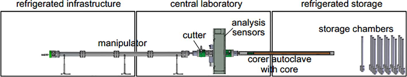
Figure 1. Scale diagram of PCATS (Schultheiss et al., 2011).
The PCATS system performs multiple roles in pressure coring operations, streamlining coring logistics through rapid autoclave recycling while also delivering fundamental scientific measurements like P-wave velocity data. PCATS can remove cores up to 3.5 meters in length from a matched pressure coring device (Fugro FPC & FRPC, Aumann HPTC and Hybrid PCS) while maintaining the original temperature and pressure (up to 35 MPa) of the formation, perform nondestructive analysis, cut core subsamples and transfer them into other chambers (Holland et al., 2008). The nondestructive analysis suite comprises gamma-ray density assessment, P-wave velocity measurement, along with both 2D radiography and 3D CT scanning. These methods yield scientifically valuable data essential for subsample selection. Depending on the sediment type, a variety of cutting techniques can be used to process the core into a “whole round” subsample (Schultheiss et al., 2008). Depending on requirements, cut cores may be placed in either basic storage chambers (10 cm - 3.5 m capacity) or dedicated instrumented cells configured for advanced geotechnical and rock physics measurements. Samples stored in storage chamber can be re-entered into the PCATS system for in-depth analysis or preparation of subsamples, depending on the needs of the experiment. Figure 2 shows the photo of PCATS central laboratory.
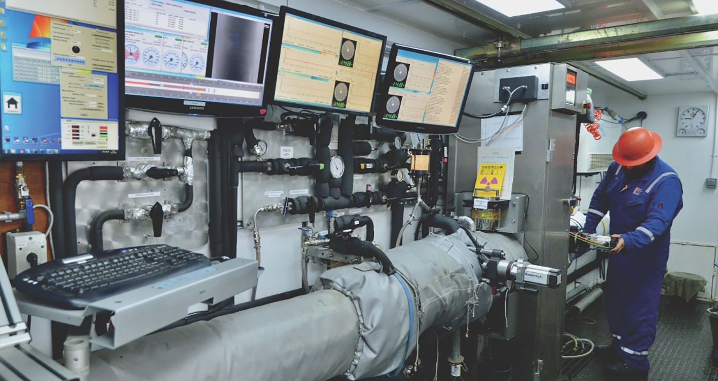
Figure 2. Photo of PCATS central laboratory.
Table 1 shows the technical parameters of PCATS. Although the PCATS system is fully functional, existing articles do not explicitly mention the adaptability limitations of core processing and performance stability under high-pressure and low-temperature conditions.
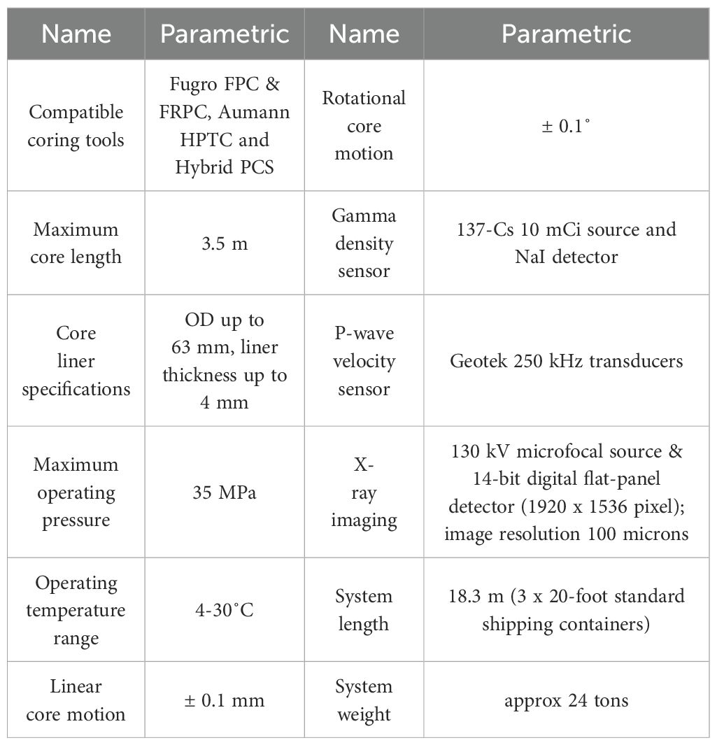
Table 1. Technical parameters of PCATS.
2.2 Mini-PCATS
Mini-PCATS (Figure 3), a compact and streamlined adaptation of the PCATS system, maintains full compatibility with standard pressure core storage chambers and third-party equipment utilizing Geotek’s flange-clamp interface. At the pressure of 35 MPa, mini-PCATS can take core sections up to 1.2 meters from the storage chamber and accurately slice them along with the plastic liner tubing, which can then be transferred to test units such as the K0 Permeameter and PCATS Triaxial for determination of physical parameters (Schultheiss et al., 2017). For samples intended to be tested in devices such as the PCATS Triaxial or the K0 Penetrometer, precise control of their geometry is essential. Mini-PCATS uses a new design for cutting core samples that consists of a rolling circular blade for cleanly cutting plastic liners and a reciprocating saw blade for cutting sediment/rock samples. The new technology allows for “square” end cutting of samples as opposed to older guillotine system that occasionally caused brittle samples to break along the laminar surfaces. By integrating an X-ray system into the mini-PCATS, the operator can visually confirm the position of the sample ends as well as check the quality of the cuts and thus make sample selection decisions. The Mini-PCATS system is compact, portable, and compatible with standard pressure chambers, but existing literature does not mention the imaging resolution limitations of X-rays in complex rock types.
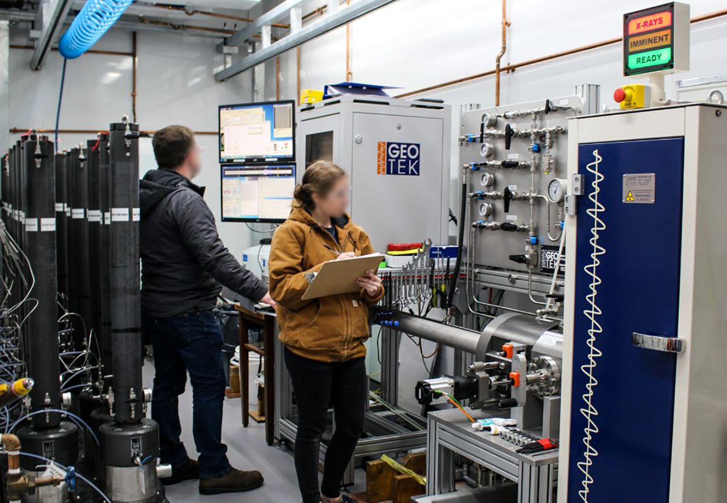
Figure 3. Picture of mini-PCATS.
Figure 4 shows the schematic diagram of the Mini-PCATS system, which primarily consists of a pressure housing, core movement mechanism, core cutter, P-wave sensors, X-ray imaging, and a ball valve. Compared to the PCATS system, the Mini-PCATS system features a newly designed core cutter that is more suitable for precise core cutting in laboratory settings; the PCATS system, on the other hand, is designed for rapid core cutting on drilling vessels. The Mini-PCATS system can be connected to a custom pressure cell via Geotek’s flange-clamp and feed core subsamples into it. The custom pressure cell is then connected to third-party equipment and feeds the core subsamples into the test chamber to complete third-party testing of the core.
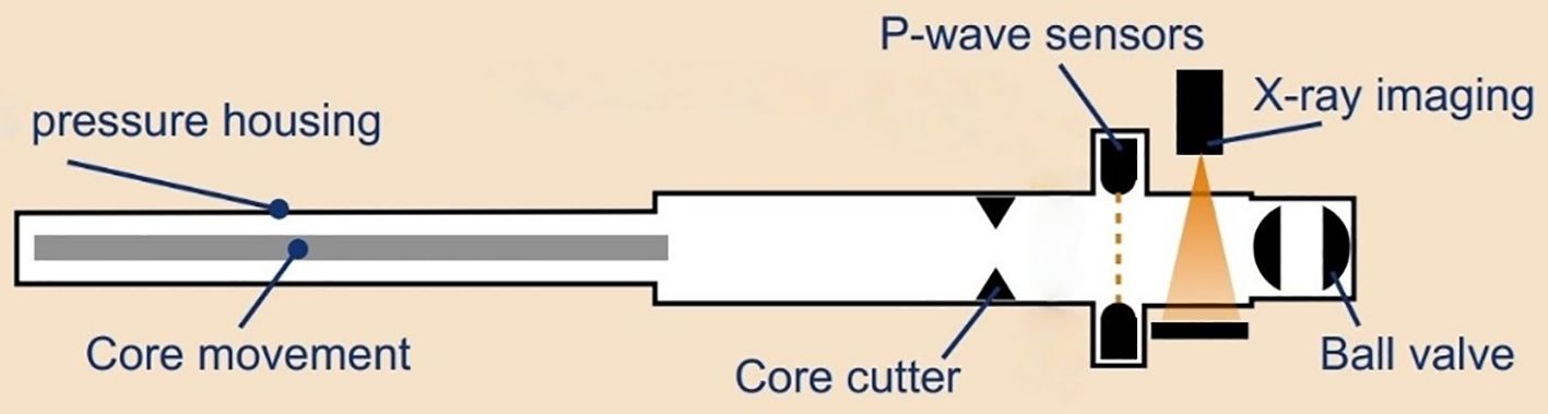
Figure 4. Schematic diagram of mini-PCATS.
2.3 HYACINTH (development of HYACE tools in new tests on hydrates)
The HYACINTH system, shown in Figure 5, was developed to explore the response behavior of sedimentary formations in pressure environments up to 250 bar (25 MPa) (Schultheiss et al., 2009). The system operates by acquiring pressure-maintained core samples from boreholes, enabling their retrieval, subdivision, and laboratory analysis under controlled conditions. A “quick fit” flange has been designed to facilitate the direct tandem connection of different chambers without the need for threaded pipe fittings or flange nuts. In this way, the pressure chambers can be quickly connected to each other without requiring rotation. For transferring cores between pressure chambers, a dedicated Manipulator Chamber has been developed. It operates using two methods: actively pushing cores between chambers or mechanically latching onto samples to withdraw them into a destination chamber. The pressure chambers in the system, which have independent pressure maintaining function, are equipped with specially developed large diameter (65mm) ball valves to ensure that the cores obtained by FPC or HRC can be flexibly transferred between the chambers (Schultheiss et al., 2006). By using an inverted cone seal interface at the end of the chamber opposite to the ball valve to connect the manipulator, the dual optimization of equipment light weighting and cost control is achieved. The HYACINTH system utilizes inverted cone seals to achieve weight reduction and cost control, but its maximum working pressure is lower than that of the PCATS system, and existing articles do not clearly state its compatibility with extra-long cores (such as 3.5 meters).
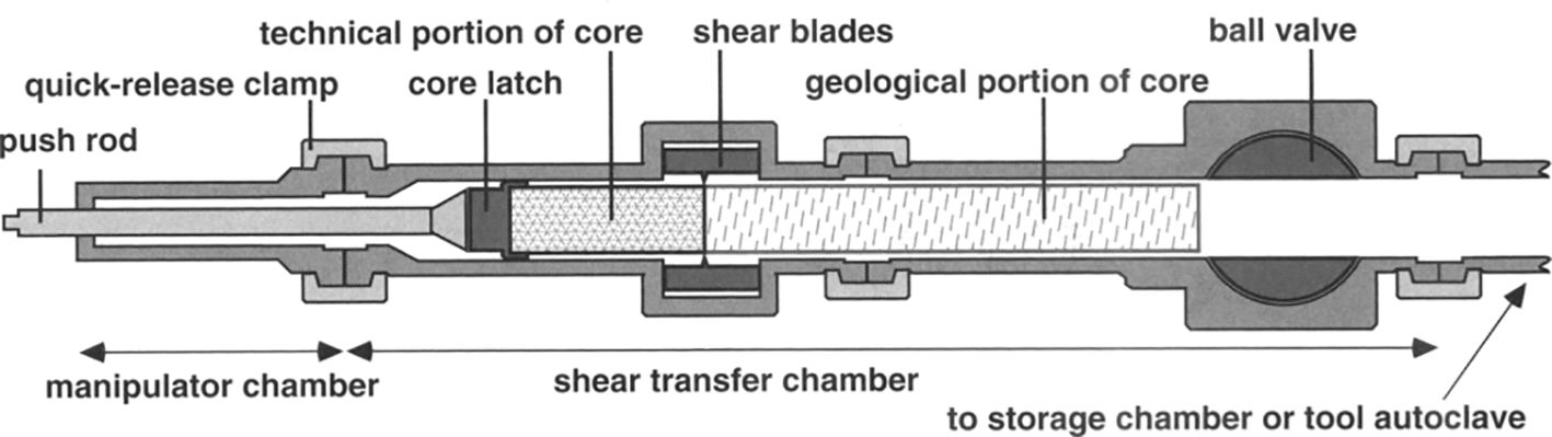
Figure 5. Diagram of the HYACINTH transfer system (Schultheiss et al., 2006).
The initial transfer operation aimed to remove the Catch Assembly from the autoclave and subsequently disassemble it into its two constituent parts: the technical module and geological sample component. To realize this function, the system consists of an autoclave in a series circuit with a Shear Transfer Chamber (STC) and a Manipulator (Figure 6). Once the pressure is equalized, the Manipulator is extended through the STC to the autoclave to engage the core. The core is then pumped back to the STC where the technical and geological sections of the Catch Assembly are separated by cutting the liner. During this process, the original coring autoclave is isolated and removed and replaced with a logging or storage chamber (Anders and Müller, 2008). Following pressure equalization, the Manipulator advances the geological core segment into either the logging or storage chamber, while retracting the remaining technical portion (still engaged with the Manipulator) back into the STC. The ball valves of the logging or storage chamber were closed and removed to allow scientific measurements to be made, while the technical component of the core was recovered and prepared for subsequent coring missions (Parkes et al., 2009). Since the FPC and HRC cores differ slightly in diameter, the STC is equipped with two specialized cutting boxes—each designed for the specific core dimensions. These boxes can be rapidly swapped thanks to the quick-release butt flange clamp system.
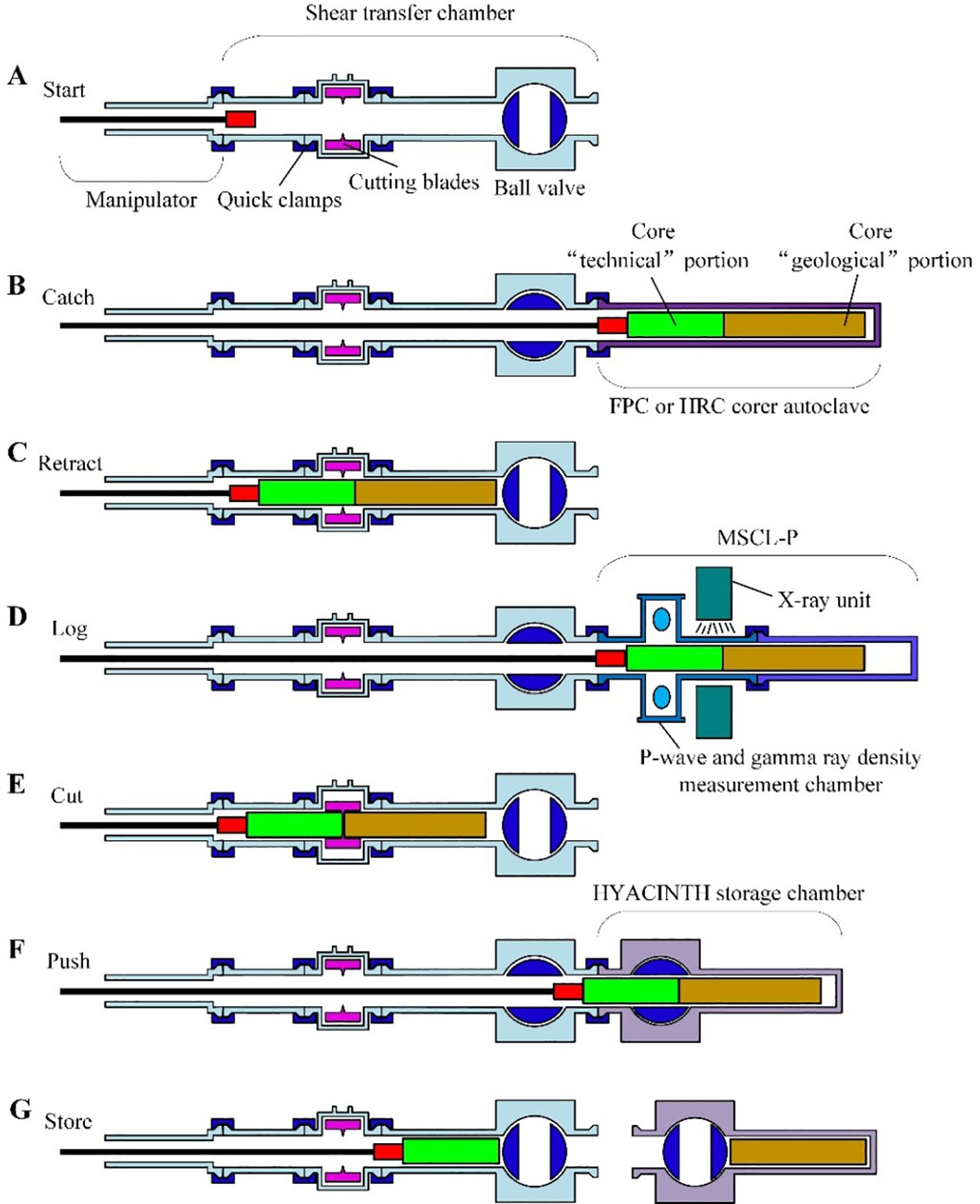
Figure 6. Workflow diagram of the HYACINTH transfer system.
2.4 A Pressure-retained transfer system
Zhejiang University, together with Dalian University of Technology and Technology and Guangzhou Marine Geological Survey, has developed a pressure-retained transfer system for natural gas hydrate cores with the financial support of the National High Technology Research and Development Program (863 Program) (Gao et al., 2020), as shown in Figure 7. The system is mainly adapted to the Long Gravity-Piston Corer (Chen et al., 2013), with a maximum working pressure of 20 MPa, which can handle cores with a length of 1.2 m and an external diameter of 67 mm, and the pressure change in the transferring process is no more than 20%. The system has the functions of core transfer, core cutting, P-wave velocity measurement and pressure core storage (Chen et al., 2019). The sub-sampler can be connected to the core storage chamber to obtain sub-samples of 200 mm in length and 20 mm in external diameter, which are mainly used for X-ray computed tomography to obtain the skeletal structure and pore storage pattern of natural gas hydrate formations. In 2016, the research team selected two test sites in the South China Sea for gas hydrate exploration areas to carry out systematic sea trials, including Site 1 with a water depth of 2,264 meters and Site 2 with a water depth of 1,130 meters (Gao et al., 2019). The system is designed specifically for natural gas hydrates and can obtain 200 mm × 20 mm subsamples for CT structural analysis, but its working pressure and core length are lower than those of the PCATS system.
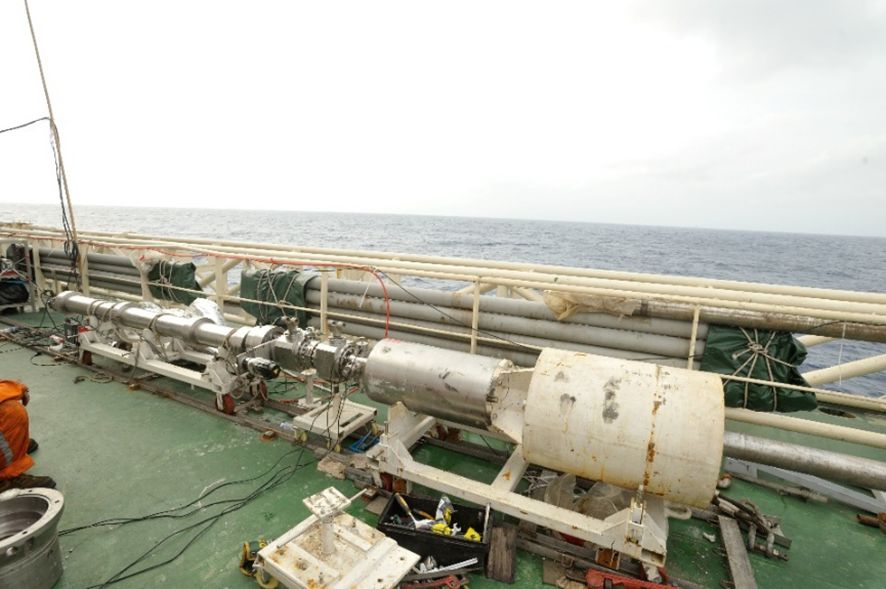
Figure 7. Documentary images from the 2016 sea trial.
2.5 A pressure core transfer and testing system
Under the support of the National Key R&D Program and the Zhejiang Key R&D Program, Zhejiang University has developed a pressure core transfer and testing system (Ren et al., 2018). As shown in Figure 8, the system is installed in three 6-meter containers, with the left container as the refrigeration facility room, which can maintain the low-temperature environment required during the test process; the middle container as the control room, which is used by the test personnel to operate the control system and the testing device (Zhang et al., 2018); and the right container as the cold storage room, which is used as the docking place of the coring tools and the core storage chambers (Zhang et al., 2019). The system can be matched with the drilling tools of seabed drilling rig or drillship to transfer a 4-meter-long core to the core storage chamber under the pressure of 35 MPa, and complete the core cutting, X-ray computed tomography, and P-wave velocity measurement of the core in the process (Ren et al., 2020). The system is compatible with a variety of coring tools and can handle 4-meter-long cores, but the efficiency of the system in handling non-homogeneous cores is not specified.
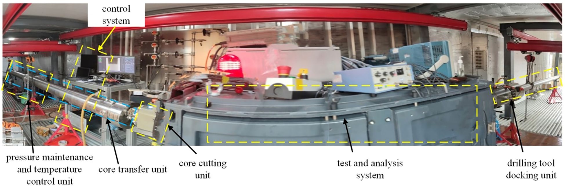
Figure 8. Pressure core transfer and testing system developed by Zhejiang University.
From March to May 2021, the system was carried on board the vessel “Marine Geology II” for sea trials in the South China Sea, during which the transfer and testing of cores from 6 stations were completed, and the results showed that the temperature of the cores could be maintained in the range of 3.0-4.5 °C, the fluctuation of pressure was less than 3.8%. Non-destructive cutting of the core can be carried out with an error of 2mm or less (Zhu et al., 2022).
2.6 Summary
The preceding sections have introduced five systems for the processing and analysis of natural gas hydrate pressure cores. To facilitate readers’ comprehensive evaluation of the performance and application scenarios of different systems, this section compares the core indicators of the five systems (Table 2). The comparison dimensions cover working pressure, core size, compatible equipment, and core functions, with a focus on the technical differences between the systems in terms of in-situ pressure retention capability and laboratory analysis compatibility.
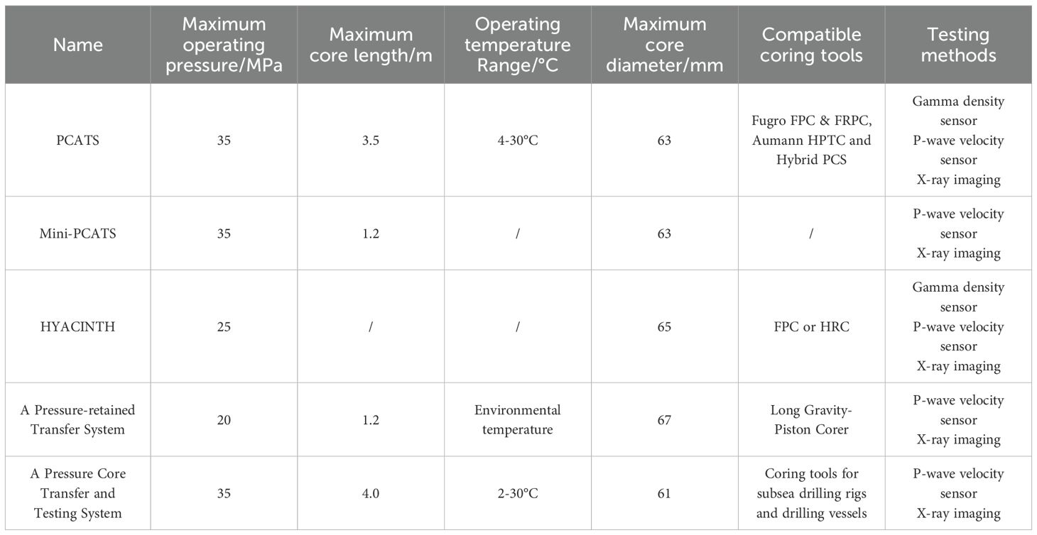
Table 2. Comparison of key indicators for core processing systems.
3 Development and application of tools for analyzing pressure core samples
The safe handling of large quantities of high-pressure, cryogenically preserved cores or core segments (either temporarily or for long periods of time) is always a difficult logistical challenge in gas hydrate pressure-holding core drilling operations. In order to obtain a large amount of formation information, a variety of tools for core analysis have been developed. This chapter describes the current research progress in gas hydrate reservoir core analysis techniques and summarizes the functional advantages and limitations of several major gas hydrate reservoir core analysis tools.
3.1 Field depressurization laboratory
Quantitative depressurization/degassing experiments are typically conducted in small storage chambers (Figure 9) on short sections of cores up to 35 cm in length and are performed in a controlled manner to accurately quantify the total amount of each phase of hydrocarbon gas in the subsample, including gas hydrates. This makes it possible to determine the concentration (saturation) of gas hydrates and the overall distribution of gas hydrates in the sedimentary sequence. Step-by-step pressure reduction is used to gradually reduce the pressure in the subsample chamber using a manifold, and the gas-liquid mixture released under each pressure gradient is quantitatively collected in the bubble metering and gas collection chambers (Schultheiss et al., 2017). Gas composition analysis is carried out throughout the depressurization process and is used to determine the component content of gas hydrates in the sediments. The presence of natural gas hydrates can be verified both kinetically and thermodynamically from pressure-time-volume relationships in depressurization experiments. Kinetic evidence is usually manifested as a pressure rebound after the bucking step, i.e., the pressure increases with time. The thermodynamic criterion for hydrate endowment is reflected in the pressure-volume relationship of the degassing process, i.e., the system pressure remains steady while the gas release volume continues to increase during the predicted hydrate stabilization pressure interval.
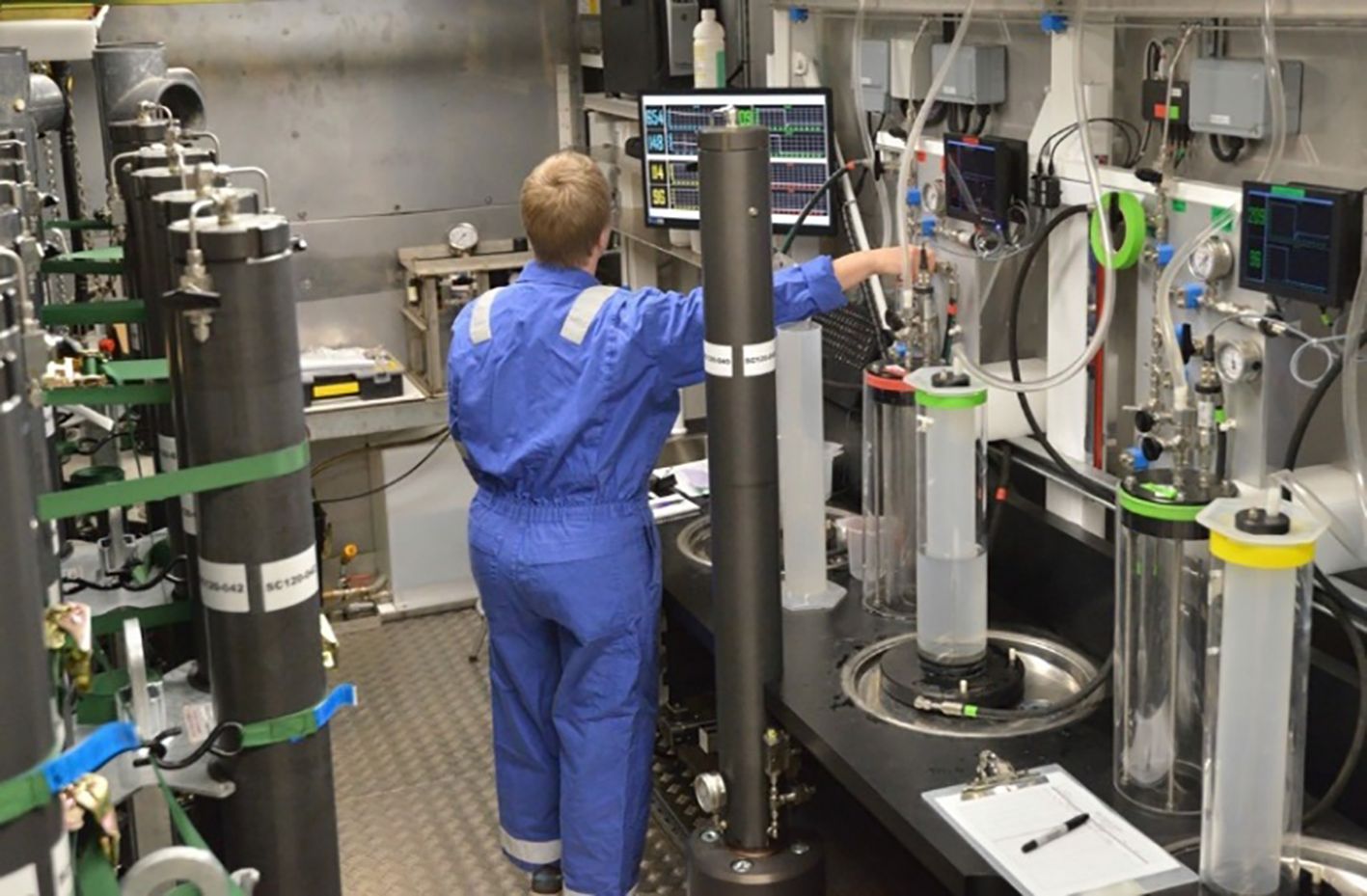
Figure 9. Depressurization laboratory for high-throughput quantitative core (Schultheiss et al., 2017).
3.2 PCATS triaxial system
The PCATS Triaxial system (Figure 10) represents a specialized mechanical testing platform capable of conducting geotechnical analyses across both small and large strain regimes on pressure-preserved core specimens of soils or rocks, while simultaneously facilitating direct permeability flow measurements. After the samples were cut in the PCATS system, they were transferred to the PCATS triaxial for testing while maintaining a maximum of 25 MPa in-situ hydrostatic pressure (Schultheiss et al., 2014). Consequently, samples of gas hydrate-bearing sediments or rocks can be taken from deep in the earth and transferred to sophisticated mechanical testing instruments under near-in-situ conditions, while keeping the gas hydrate in its stabilization field (Priest et al., 2015). The complete triaxial pressure control within the system enables acquisition of reliable geomechanical properties and accurate permeability measurements. A viewing window in the main pressure housing allows direct observation of the delicate process of transferring the sample from the plastic liner to the thin rubber membrane.
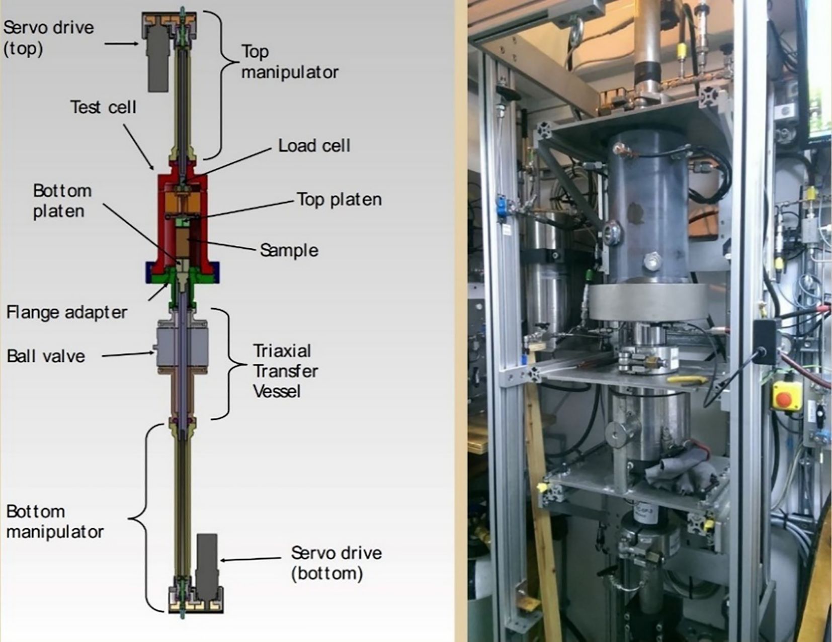
Figure 10. Schematic diagram PCATS Triaxial system.
The test chamber features modular drive heads that enable multiple testing modalities: a resonant column configuration for small-strain characterization and a conventional triaxial setup for large-deformation analysis. The small strain resonance test uses an electromagnetic drive to apply a torsional load to the specimen to determine the resonance frequency of the specimen-drive system (Schultheiss et al., 2011). Based on the calibration method and elastic wave theory, the shear modulus of the specimen and the shear wave propagation velocity can be calculated from this. The sample’s large-deformation response is characterized through conventional triaxial testing methodology, enabling comprehensive determination of stress-strain behavior under controlled loading conditions. An incremental uniaxial load is applied to the specimen and the change in axial deformation with load is monitored. For permeability testing, the differential pressure method is used, which is realized by measuring the fluid flow rate (Liang et al., 2017).
3.3 K0 Permeameter
Complementing the PCATS triaxial system, a newly developed test cell was specifically designed to acquire permeability data under simulated in-situ K0 stress conditions. This K0 system (Figure 11) has a simpler and lower cost structure that improves sample handling efficiency and maintains in-situ hydrostatic pressure of up to 35 MPa throughout sample cutting and transfer, enabling direct core transfer to the K0 permeameter. The test cell enables comprehensive evaluation of both consolidation properties and permeability characteristics of the samples. A flexible rubber sleeve is used to wrap the specimen, and the effective stress is applied to restore the in-situ stress state of the formation by independently controlling the perimeter and pore pressures. Pressure core samples (25-80 mm length) extracted from PCTB storage can be precisely sectioned using either PCATS or mini-PCATS, then transferred to the K0 permeameter test cell. The cell features an integrated ball valve for isolation, enabling disconnection from mini-PCATS and subsequent integration with the Axial Load Transfer System (ALTS) (Schultheiss et al., 2017). This combined system is capable of extruding the sample from the liner tube into a flexible rubber sleeve within the test cell. After completing the sample extrusion into the rubber sleeve at a constant pressure, a perimeter pressure and vertical load (via ALTS) can be applied as needed to return the sample to its in-situ stress state prior to permeability testing. Permeability testing is performed by direct seepage measurements through the porous stone at the top and bottom of the sample. The K0 permeameter test chamber interfaces with the ALTS, which stabilizes the sample in horizontal position during transfer operations before reorienting vertically for analytical procedures.

Figure 11. Schematic diagram of the K0 system (Schultheiss et al., 2017).
3.4 The HYACINTH subsampling system
The HYACINTH subsampling system, which allows subsampling under pressure and then relocating subsamples to dedicated analysis chambers for subsequent testing and experimentation, is designed to meet varied research requirements, the technology supports applications ranging from gas chromatography and pore-water extraction to biological incubation and geomechanical testing. A subsampling tool such as the one shown in Figure 12 allows for a 10-cm-long complete core segment to be intercepted from anywhere in a 1-m-long FPC or HRC core and transferred to a small core segment storage compartment (the precise location of this sub-segment can be determined after analyzing logging data from cores acquired under pressure-holding conditions). Figure 12 illustrates the process of transferring pressure core subsamples to the microbiology experiments chamber: (A) the Core Section Chamber (CSC) maintains pressure integrity in whole-round core segments while providing fluid/gas connections to adjacent analysis chambers; (B) following chamber pressurization, the CSC’s large-bore ball valve is actuated to permit transfer of core segments into the extrusion tube via mechanical displacement, and the rotating cutter obtains an axial subsample and pushes it into the microbiology chamber; and (C) a sterile subsample is obtained for microbiology experiments (Schultheiss et al., 2006).
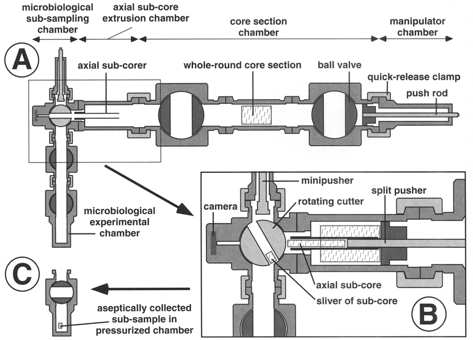
Figure 12. Diagram of subsampling tool (Schultheiss et al., 2006).
3.5 PCCT (pressure core characterization tools)
Developed by Georgia Tech, the Pressure Core Characterization Tools comprise a suite of instrumented pressure vessels that were operationally deployed in Sapporo, Japan (January 2013) to characterize gas hydrate-bearing pressure cores from the 2012 Eastern Nankai Trough campaign. The system measured key properties including geomechanical, hydraulic, electrical, and biological parameters. The manipulator (MAN) is a longitudinal positioning device capable of gripping and transferring cores between chambers under the required temperature and pressure conditions (Santamarina et al., 2012a). Figure 13 illustrates the standard operating procedure: the sample is first extracted from the storage compartment to the manipulator, which then pushes it to the test chamber. The length (Lman) of the MAN (including the temporary storage chamber) is designed as 3.5 times the core length (Lcore). For a standard core length of 1.2 meters, the system uses a telescopic screw drive mechanism (stepper motor driven) with a stroke of 2.6 meters and a positioning resolution of better than 1 mm (Yamamoto, 2015). A detachable flange clamp connection is used to interface with the 1.3-meter temporary storage chamber, equipped with a visualization window for continuous monitoring of the manipulator’s positioning. The 1.2-meter core handled supports segmental cutting. The cutting tool (CUT) is configured with a linear or circular saw blade in a clamped chamber for saw-based machining that results in flat end surfaces and minimizes sample disturbance. The CUT can be mounted in tandem between the MAN and other test or storage chambers as required (Figures 13d, e).
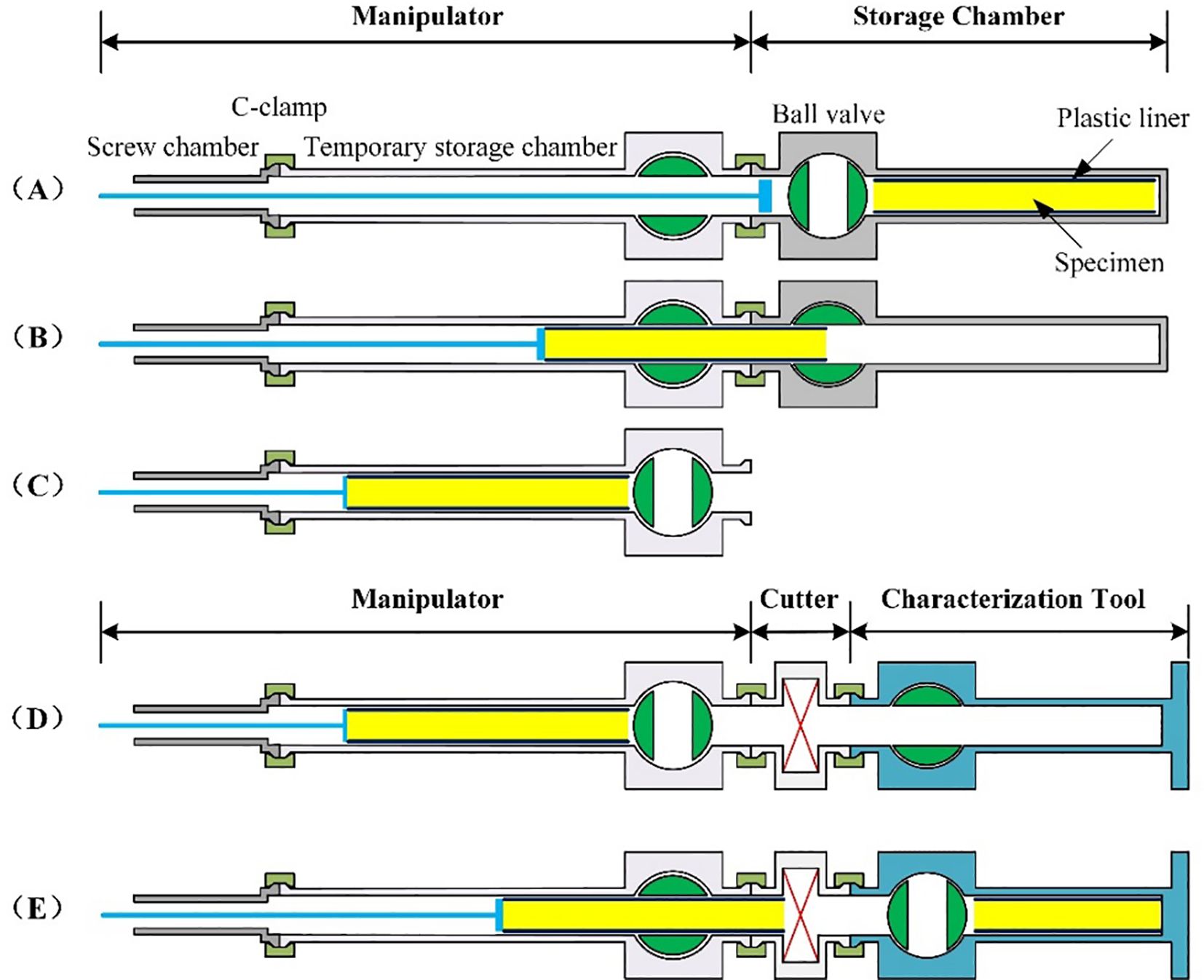
Figure 13. Pressure core manipulation (Santamarina et al., 2012b).
Instrumented Pressure Testing Chamber (IPTC) (Figure 14A). The chamber was specifically designed to enable fluid sampling while simultaneously acquiring geophysical and geotechnical data, including compressional/shear wave velocities, undrained shear strength, bulk electrical conductivity, and in-situ temperature profiles. The cylindrical chamber is equipped with two sets of four radially symmetrical port pairs. The first set of ports is used to drill holes (8 mm in diameter) in the plastic liner so that the contact probes in the subsequent ports can be inserted into the sample (Yun et al., 2006). The IPTC is connected to the MAN and the extension chamber on each side to support arbitrary point measurements over the full length of the core during testing. The design of eight inspection interfaces makes it an ideal multifunctional module for conducting production experiments related to reservoir calibration modeling.
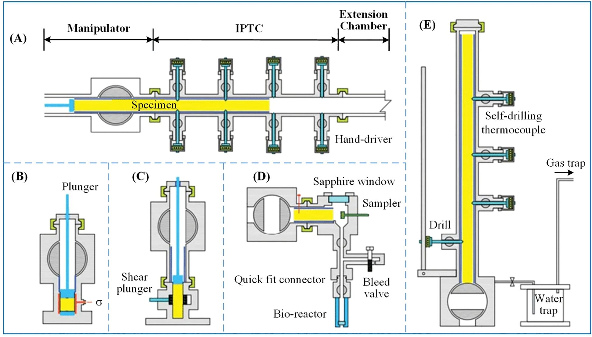
Figure 14. Schematic diagrams of characterization chambers (Santamarina et al., 2012).
Effective Stress Chamber (ESC) (Figure 14B). The ESC can precisely control the temperature and pressure to reconstruct the in-situ effective stress environment of the sedimentary layer. During the experiment, the sample is sealed by a flexible membrane and subjected to an effective stress of 3MPa, which realistically simulates the in-situ stress state generated by the weight of the overlying strata. Small-strain stiffness, compressibility, hydraulic conductivity, volume contraction upon dissociation, and hydrate saturation were measured. Georgia Tech completed the development and laboratory testing of the equipment in 2006 under a Joint Oceanographic Institutions (JOI) grant, and its first field application was implemented by the Korea Institute of Geoscience & Mineral Resource (KIGM) in conjunction with Geotek (Dai et al., 2017).
Direct Shear Chamber (DSC) (Figure 14C). The core of the DSC is a thick-walled stainless-steel ring that shears the center third of the specimen by propulsion. The DSC system incorporates three key components: (1) a stress-recovery piston (functionally equivalent to the ESC system), (2) a liner capture mechanism that intercepts the plastic sleeve prior to specimen transfer into the shear chamber, and (3) a compact lateral actuator assembly that drives the side piston for ring displacement. The maximum shear displacement of the system is 15mm, which allows both peak shear strength and residual strength values to be obtained. Through DSC testing, the researchers determined the compressive deformation and shear strength of rock samples before and after hydrate decomposition in a 3 MPa in situ effective stress environment (Sapporo Scientific Team, 2013). The P-wave velocity and temperature were continuously monitored during the experiment, covering loading, shearing and dissociation stages. The DSC data were also utilized to study the creep deformation and volume shrinkage effects induced by dissociation.
Sub-sampling Tool for Bio-Studies (BIO) (Figure 14D). The BIO is disengaged from the system once the core section is loaded by the MAN, which allows for the contamination-free transfer of multiple samples to the bioreactor while maintaining the stable temperature and pressure of the hydrate and the addition of microbial nutrients via a high-pressure injection system (Santamarina et al., 2012). The operational protocol comprises four sequential steps: (1) displacement of liquids with nitrogen purging, (2) surface sterilization of core interfaces and chamber decontamination, (3) rotary coring extraction of sub-samples, and (4) transfer of specimens into pre-conditioned bio-reactors containing 10 mL of nutrient medium. All operations can be monitored in real time through the sapphire window. The bioreactor is easy to replace: simply close the dual ball valve system and disconnect the quick connect coupler. The unit allows the acquisition of a large number of samples from a single core section while maintaining in-situ hydrostatic pressure.
Controlled Depressurization Chamber (CDC) (Figure 14E). The CDC is designed to effectively protect core lithology characteristics and capture critical data during depressurization with minimal human resource requirements. This stand-alone device has a built-in drilling station to perforate the liner at selected locations in order to reduce the longitudinal expansion of the specimen. Gas pressure and temperature are continuously monitored by pressure transmitters and thermocouples. The system also integrates three sets of self-drilling thermocouples, which are pierced into the core during the depressurization process to obtain real-time temperature data inside the sediment. A 2-liter water collector and a 55-liter gas collector are configured in series at the outlet end of the pressure-reducing control needle valve to achieve quantitative collection of the output water and gas (Yun et al., 2010).
3.6 PNATs (the pressure core nondestructive analysis tools)
To address the challenge of hydrate dissociation under atmospheric conditions, researchers developed the TACTT system (Figure 15), enabling complete sample preparation and testing while preserving hydrate stability conditions. Typically, pressurized triaxial test cells use stainless steel chambers capable of withstanding tens of megapascals of pressure, but TACTT uses transparent acrylic chamber, which allow visual confirmation of the condition of the specimen, both in terms of specimen shape and the condition of the end face after the transport process. The triaxial chamber with the bottom observation window design realizes the visualization and monitoring of the pressure core. The hydraulic system provides up to 16 MPa of perimeter and pore pressure, and the control accuracy is maintained within ±0.01 MPa. The instrument is suitable for sample sizes from 50.8 to 53.6 mm in diameter and less than 110 mm in height. The system provides a maximum load of 100 kN and a measurement accuracy of one thousandth of the full scale (Yoneda et al., 2013; Sapporo Scientific Team, 2013).
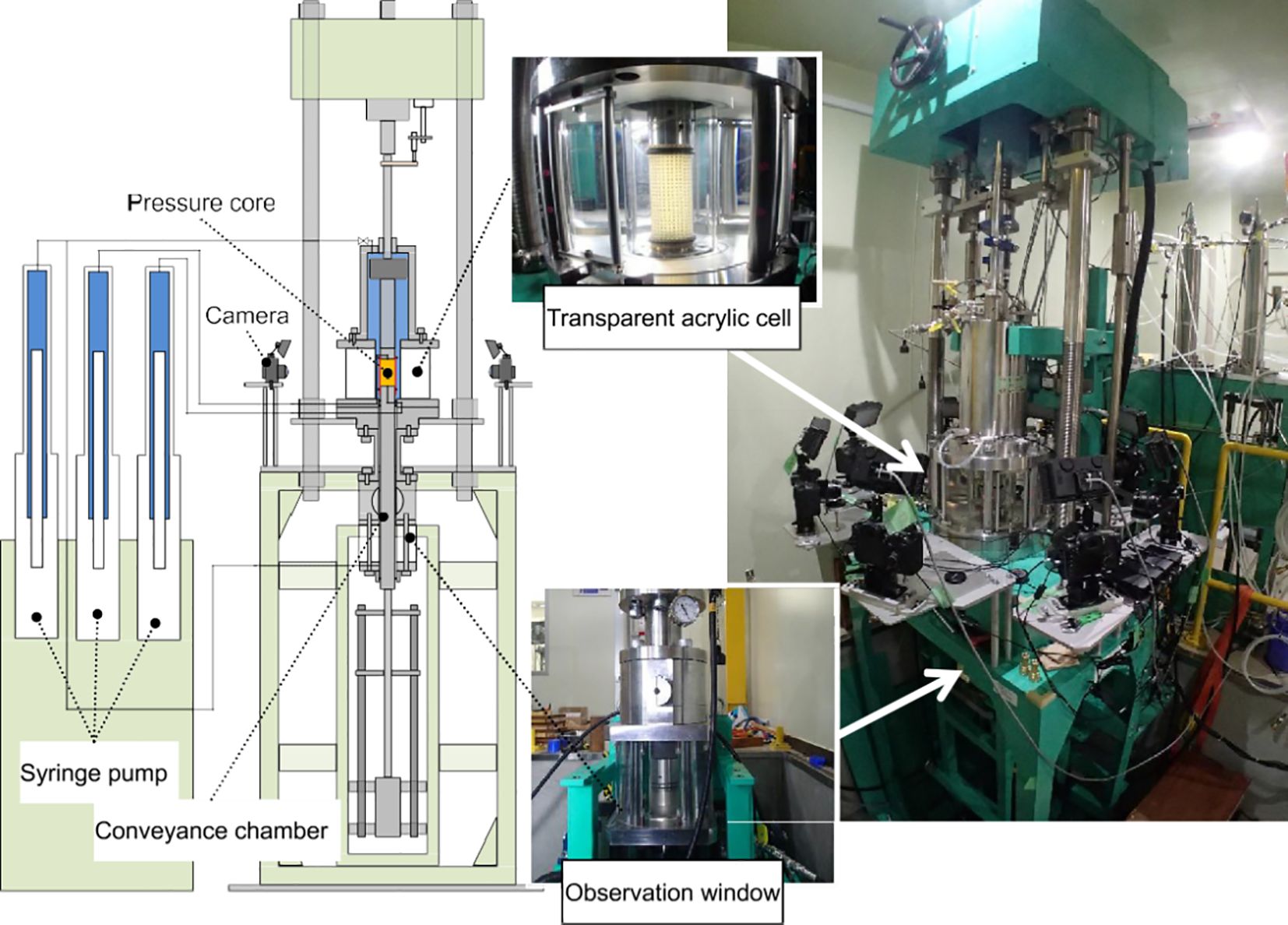
Figure 15. Schematic diagram of the TACTT system (Yoneda et al., 2015).
All pressure cores, comprising sediment-filled plastic liners (ID = 53.6 mm), were preserved in pressurized vessels maintaining in-situ conditions of 10 MPa and 4°C (Figure 16a). During testing, the pressure cores with plastic liner tubes were extracted by the PNATs Manipulator (Figure 16b). (Figure 16c) shows a schematic of the pressure retaining core transfer process: (i) the storage chamber was docked with PNATs and fluidly pressurized to achieve pressure balance on both sides of the ball valve; (ii) the pressure was stabilized by a syringe pump after the ball valve was opened; (iii) a manipulator transferred the cores wrapped in plastic liner tubes to the temporary storage chamber at 10 MPa; (iv) the storage chamber’s ball valve was shut; and (v) the cores and the liner tubes were cut into 10-cm standard segments using a diamond saw (Yoneda et al., 2017). After cutting, the 10-centimeter-long core segment is maintained in a purpose-built pressure vessel designed for core preservation. This pressure chamber holds the plastic liner and pushes only the intact pressure core sediment into the transfer chamber. After docking the transfer chamber to the TACTT, the sample is moved into the triaxial pressure chamber via a lift table. The core sample was eventually pushed into clear acrylic chamber-sealed sleeves with locator marks (Figure 16d). Friction between the core sidewalls and the sleeve is minimized by maintaining consistent pressure inside and outside the sleeve during the transfer process. The sample is equipped with porous metal filters integrated into both the top endcap and the base pedestal, which link it to the pore fluid pressure system. During testing, syringe pumps regulate the confining (cell) pressure, as well as the pore fluid pressures at the upper and lower ends, while the core is secured inside the sleeve and the endcaps are properly positioned. A vertical displacement transducer records the sample’s axial deformation. Additionally, target markers placed on the sleeve (Figure 16d) are monitored via image analysis, achieving an accuracy of ±0.1 mm (± 0.1% strain). This precision is more than adequate to detect even minor volumetric changes in the sample.
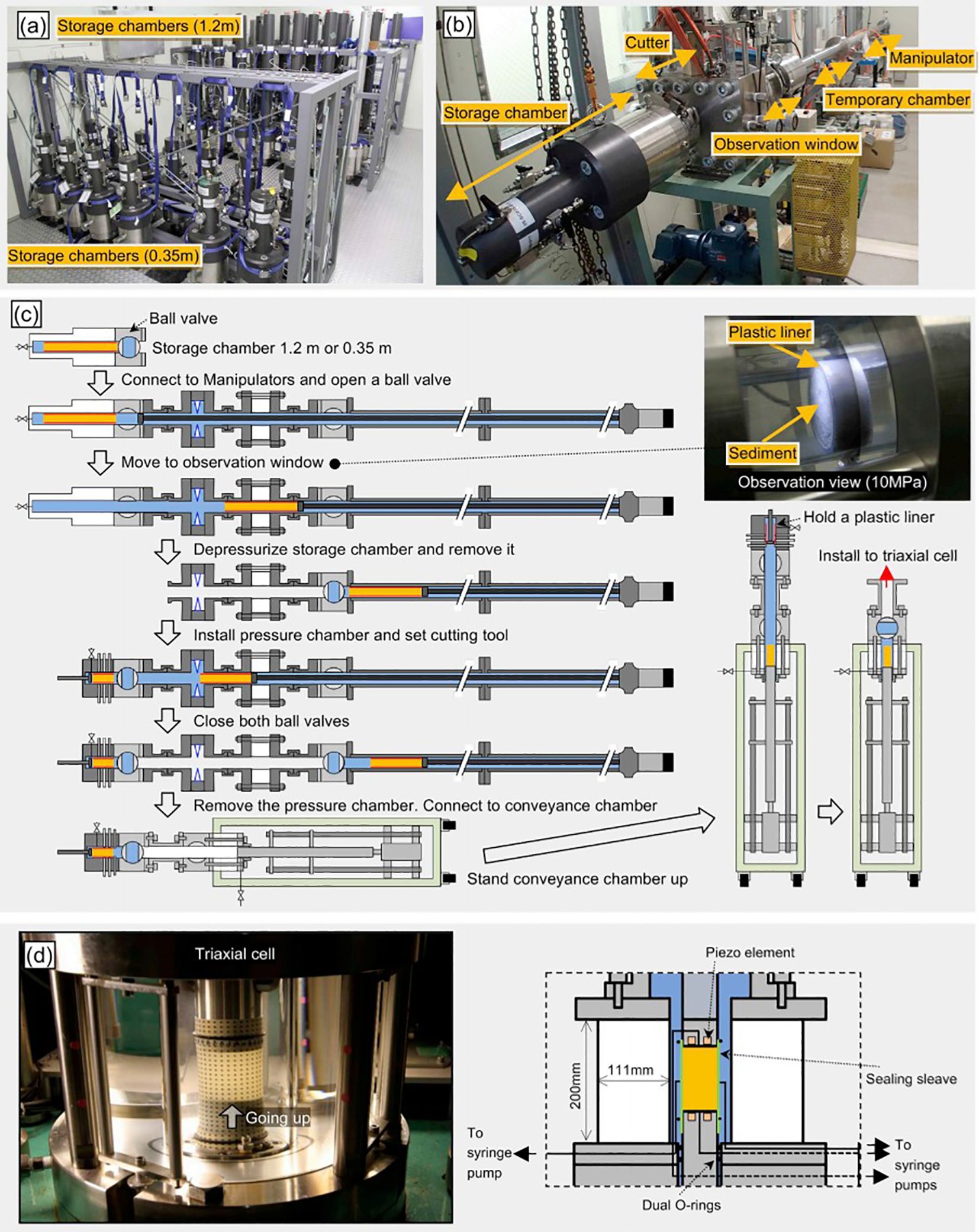
Figure 16. Pressure core handling protocol (a) Visual documentation of pressurized storage chambers. (b) Preparation of specialized core manipulation equipment. (c) Pressure core transfer procedures. (d) Photograph of the process of transferring the pressure core into the sealing sleeve (Yoneda et al., 2019).
During June-July 2012, three pressure core technologies (PCATs, PCCTs, and PNATs) underwent field evaluation at the eastern Nankai Trough, assessing their performance in recovering gas hydrate-bearing sediments. These tests formed part of the MH21 program’s 2012-2013 offshore methane hydrate production trials (Yamamoto, 2015). Historical pressure core test data are compiled in Table 3.
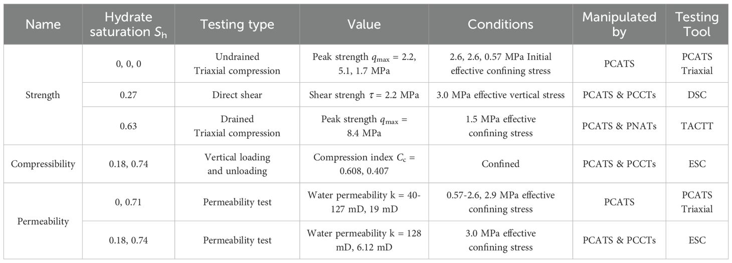
Table 3. Previous pressure core-based element test results.
3.7 The fidelity triaxial test device
As shown in Figure 17, the fidelity triaxial test device developed by Zhejiang University includes a sample transfer system, a triaxial host system, support structures, a data acquisition system, a temperature control system, and a pressure pressurization system (Yuhong et al., 2025). The device can be adapted to a pressure core transfer and testing system developed by Zhejiang University for quasi-in-situ mechanical characterization of gas hydrate reservoirs. The temperature control system operates within a range of 0 to 4 °C, ensuring the stability of the hydrate state and maintaining sediment mechanical behavior. The device accommodates sample dimensions of a diameter of φ39 mm and a maximum length of 78 mm. It can apply an axial force ranging from 2 to 80 kN and achieve a maximum loading confining pressure of 30 MPa. Table 4 shows main technical indicators of the fidelity triaxial test device.
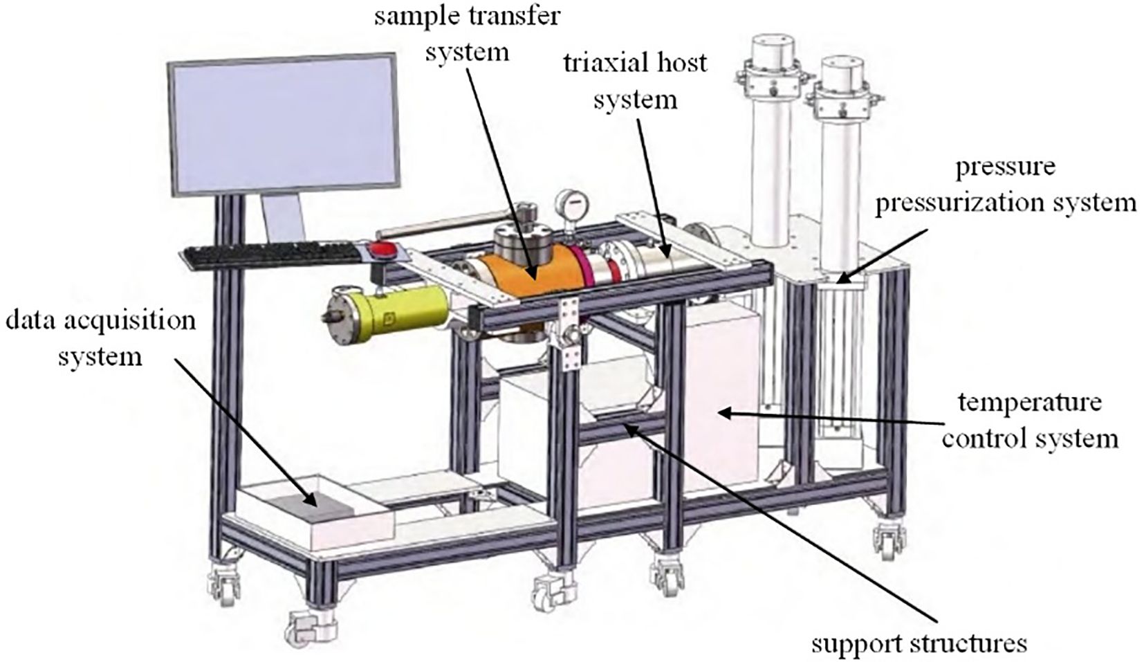
Figure 17. Schematic diagram of fidelity triaxial test device (Wang et al., 2025).
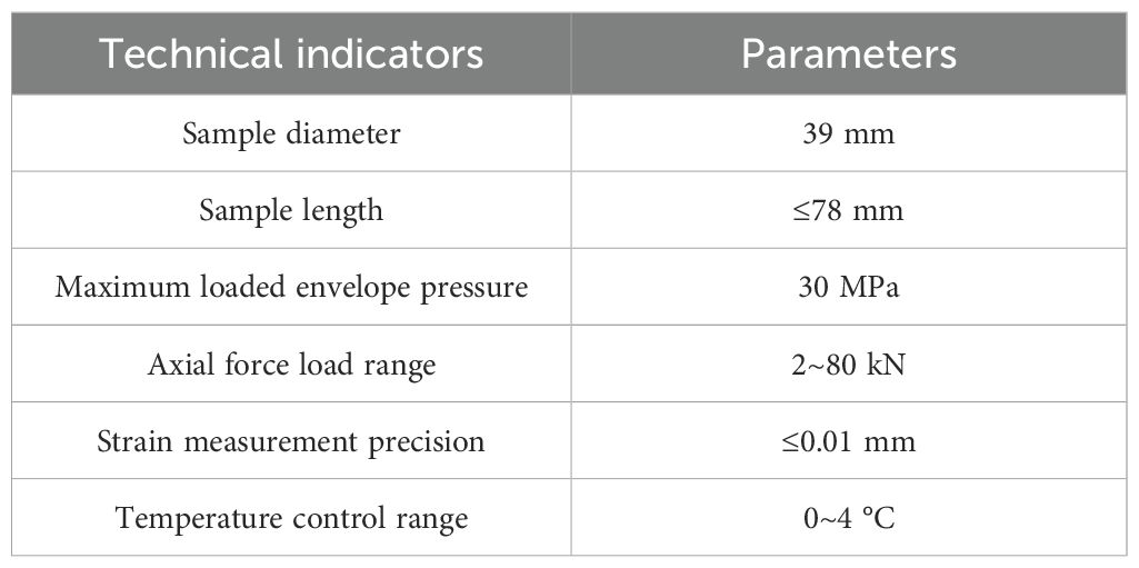
Table 4. Main technical indicators of the fidelity triaxial test device.
3.8 The field parameter test system for gas hydrate pressure holding core samples
The field parameter test system for gas hydrate pressure holding core samples developed by the College of Engineering of China University of Geosciences (Wuhan) is shown in Figure 18. The system is mainly composed of core capture and cutting unit, sampler pressure maintaining unit, core sample parameter testing unit, core sample storage unit, temperature and pressure maintaining unit, etc. The core sample parameter testing unit is in the shape of a hollow cylinder with a total length of 1.7 m, including quick coupling, ball valve, temperature sensor, pressure sensor, acoustic wave probe, resistivity probe, strength probe, wave velocity meter, resistivity meter, and shear strength meter. Temperature sensors and pressure sensors are used to monitor the temperature and pressure inside the core sample parameter testing unit, respectively. Acoustic wave probes are symmetrically distributed to measure the P-wave velocity of hydrate core samples. Resistivity probes are distributed at the front and rear to measure the resistivity of hydrate core samples. Strength probes and shear strength meters are used to measure the shear strength of hydrate core samples. Before the core is transferred to the parameter testing unit with pressure, the testing probe is to be on the outside of the core pressure cylinder, and when the core reaches the testing position, the probe is to be pierced into the inside of the hydrate core from the outside for parameter testing. In order to rotate the core liner in a pressure-holding environment to ensure that the acoustic, resistivity, and shear strength probes are aligned with the appropriate measurement points, a core liner rotation and positioning device was designed. The monitoring component allows you to see if the test holes are aligned with the test points on the core liner.
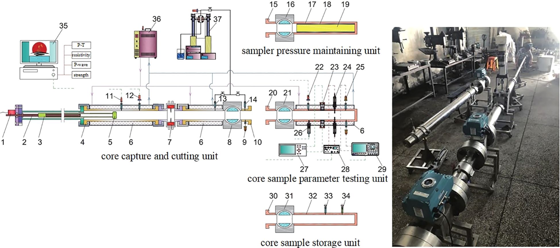
Figure 18. The schematic diagram of the field parameter test system for gas hydrate pressure holding core samples. 1-Step motor; 2-Screw; 3-”C” tube; 4-Quick coupling; 5-Grabber; 6-Water jacket; 7-Cutter; 8-Ball valve; 9-Safety valve; 10-Quick coupling; 11-Temperature sensor; 12-Pressure sensor; 13-Pressure tracking port; 14-Pressure tracking port; 15-Quick coupling; 16-Ball valve; 17-Core inner tube; 18-Core liner; 19-Core; 20-Quick coupling; 21-Ball valve; 22-Temperature sensor; 23-Sonic probe; 24-Resistivity probe; 25-Strength probe; 26-Pressure sensor; 27-Wave velocity meter; 28-Resistivity meter; 29-Cutting shear strength meter; 30-Quick coupling; 31-Ball valve; 32-Storage cylinder; 33-Temperature monitoring indicator; 34-Pressure monitoring indicator; 35-Data acquisition processor; 36- Thermostatic circulating water bath; 37-Double-cylinder constant-speed constant-pressure pump.
4 Conclusions and prospects
Natural gas hydrate reservoir core pressure-holding transfer and testing systems are indispensable investigation equipment for hydrate resource exploration and exploitation. Although countries worldwide have developed various analytical tools for more than 20 years, they are still inadequate. With the arrival of the period of commercial exploitation of hydrate resources, the requirements for analytical tools are increasing. Integration, intelligence and diversification are the future development trends of hydrate core analysis tools, which aim to carry out more complex field tests and obtain reliable data and information. Therefore, the development prospects of gas hydrate reservoir core pressure-holding transfer and testing technology are discussed from the following aspects.
1. Automatization. Pressure retention transfer and testing in the field is very important due to the impact of long-term pressure retention storage on the physical properties of gas hydrate reservoir cores. However, handling a large number of cores under high pressure and low temperature for a long period of time is always a challenge due to the complexity of the equipment operating procedures and the need for human intervention in most cases, resulting in long processing and testing times for pressure cores. This calls for more automated equipment to reduce core handling times and make it possible to efficiently handle large numbers of cores in a short period of time.
2. Functional integration. The cost of removing natural gas hydrate reservoir cores is high, and the number of high-quality core samples is very limited. In order to obtain as much test data as possible from the limited pressure cores, it is necessary to develop multiple physical properties joint testing techniques in the field, so that the test results can be corroborated by multiple means in the limited space, limited time and limited cores.
3. Develop a multi-scale coupled permeability testing system. By integrating in-situ CT imaging with an intelligent pressure control module, combined with digital core simulation and joint inversion of experimental data, establish a dynamic correction model for the Klinkenberg effect that considers pore structure characteristics, enabling precise conversion from apparent permeability to intrinsic permeability, and providing more reliable permeability parameters for natural gas hydrate reservoir evaluation.
4. Develop a preparation and testing system for fissure-type natural gas hydrate deposits. Develop a large-scale hydrate fissure simulation device that integrates a triaxial stress loading system with real-time CT monitoring. Develop directional fracturing methods based on acoustic/microwave excitation to achieve precise control of the fissure network. Provide technical support for the industrial development of natural fissure-type hydrate reservoirs.
5. During the processing of natural gas hydrate cores, the risk of hydrate dissociation is a key factor affecting sample fidelity and experimental reliability. Although existing systems (such as PCATS and Mini-PCATS) suppress dissociation through high-pressure, low-temperature environments, local temperature increases, pressure fluctuations, and pad damage caused by mechanical cutting may still lead to hydrate decomposition at the microscopic scale. Future improvements could involve developing liquid nitrogen-assisted blades to suppress cutting-induced thermal effects, or dynamically adjusting pressure and cooling rates to precisely maintain the metastable window. Such enhancements would further enhance the accuracy of hydrate exploration data.
6. Current ship-based hydrate core testing technologies (such as CT and P-wave) prioritize screening efficiency over absolute accuracy. However, the unique phase transition characteristics of hydrates and sample heterogeneity pose challenges to traditional geotechnical testing methods (such as triaxial tests). Future research should focus on: 1) Developing calibration methods suitable for hydrate cores and establishing an error assessment system that accounts for phase transition effects; 2) Integrating machine learning technology to enhance the consistency of in-situ measurements through multi-modal data fusion (CT-P-wave-resistivity); 3) Constructing a hydrate core database to quantify the correlation between geological factors and testing variability. These efforts will drive the transformation of hydrate core testing from qualitative screening to quantitative characterization, providing a more reliable data foundation for resource assessment.
Author contributions
QG: Funding acquisition, Writing – original draft. JC: Writing – review & editing, Funding acquisition. LN: Investigation, Writing – original draft. JS: Funding acquisition, Writing – review & editing.
Funding
The author(s) declare financial support was received for the research and/or publication of this article. This study was supported by the Science Foundation of Donghai Laboratory (No. L24QH011 and No. L24QH010), Key R&D Program of “Jianbing Lingyan+X” in Zhejiang Province (2024SSYS0089) and the Donghai Laboratory (DH-2022ZY0007).
Conflict of interest
The authors declare that the research was conducted in the absence of any commercial or financial relationships that could be construed as a potential conflict of interest.
Generative AI statement
The author(s) declare that no Generative AI was used in the creation of this manuscript.
Any alternative text (alt text) provided alongside figures in this article has been generated by Frontiers with the support of artificial intelligence and reasonable efforts have been made to ensure accuracy, including review by the authors wherever possible. If you identify any issues, please contact us.
Publisher’s note
All claims expressed in this article are solely those of the authors and do not necessarily represent those of their affiliated organizations, or those of the publisher, the editors and the reviewers. Any product that may be evaluated in this article, or claim that may be made by its manufacturer, is not guaranteed or endorsed by the publisher.
References
Abegg F., Hohnberg H. J., Pape T., Bohrmann G., and Freitag J. (2008). Development and application of pressure-core-sampling systems for the investigation of gas-and gas-hydrate-bearing sediments. Deep Sea Res. Part I 55, 1590–1599. doi: 10.1016/j.dsr.2008.06.006
Abid K., Spagnoli G., Teodoriu C., and Falcone G. (2015). Review of pressure coring systems for offshore gas hydrates research. Underwater Technol. 33, 19–30. doi: 10.3723/ut.33.019
Anders E. and Müller W. H. (2008). “Compact Multipurpose sub-sampling and processing of in-situ cores with PRESS (Pressurized Core Sub-sampling and Extrusion System),” in Proceedings of the 6th International Conference on Gas Hydrates (ICGH 2008) (CANADA, Vancouver, British Columbia).
Borah U. B., Pandey G., Sarma S., Molokitina N., and Chauhan G. (2024). “Affordable and Clean energy: natural gas hydrates and hydrogen storage,” in Clean and Renewable Energy Production. (Hoboken, NJ: Wiley), 87–121.
Boswell R. (2007). Resource potential of methane hydrate coming into focus. J. Petroleum Sci. Eng. 56, 9–13. doi: 10.1016/j.petrol.2006.09.002
Chen J. W., Fan W., Bingham B., Chen Y., Gu L. Y., and Li S. L. (2013). A long gravity-piston corer developed for seafloor gas hydrate coring utilizing an in-situ pressure-retained method. Energies 6, 3353–3372. doi: 10.3390/en6073353
Chen J. W., Gao Q. L., Liu H. H., Zhang H. Q., Xiao B., and Liu F. L. (2019). Development of a pressure-retained transfer system of seafloor natural gas hydrates. Environ. Geotechnics 8, 529–538. doi: 10.1680/jenge.19.00062
Chen H., Sun J., Wang X., et al. (2024). Environmental challenges on hydraulic fracturing stimulation in the natural gas hydrate reservoir: a mini-review. Energy Fuels 38, 17278–17296. doi: 10.1021/acs.energyfuels.4c03117
Dai S., Boswell R., Waite W., Jang J., Lee J. Y., and Seol Y. (2017). “What has been learned from pressure cores,” in Proceedings of the 9th International Conference on Gas Hydrates (ICGH-2017, Denver, USA).
Diaconescu C. C., Kieckhefer R. M., and Knapp J. H. (2001). Geophysical evidence for gas hydrates in the deep water of the South Caspian Basin, Azerbaijan. Mar. Petroleum Geology 18, 209–221. doi: 10.1016/S0264-8172(00)00061-1
Diaconescu C. C. and Knapp J. H. (2000). Buried gas hydrates in the deepwater of the South Caspian Sea, Azerbaijan: implications for geo-hazards. Energy Explor. Exploitation 18, 385–400. doi: 10.1260/0144598001492184
Fazioli R. (2024). Economic analysis and evaluations of natural gas hydrates exploitation by injection of CO2: hydrate-based carbon capture technologies. (Pisa & Rome: Fabrizio Serra Editore), 1–161.
Gao Q., Chen J., Liu J., Gu L., Liu F., and Geng X. (2020). Research on pressure-stabilizing system for transfer device for natural gas hydrate cores. Energy Sci. Eng. 8, 973–985. doi: 10.1002/ese3.562
Gao Q., Zhang P., Zhu H., Ren Z., Le X., and Chen J. (2019). “Development of analysis and transfer system of seafloor natural gas hydrate pressure core,” in ISOPE International Ocean and Polar Engineering Conference. (Cupertino, CA: International Society of Offshore and Polar Engineers (ISOPE)), ISOPE-I-19-551.
He S., Peng Y., Jin Y., Wan B., and Liu G. (2020). Review and analysis of key techniques in marine sediment sampling. Chin. J. Mechanical Eng. 33, 1–17. doi: 10.1186/s10033-020-00480-0
Holland M., Schultheiss P., Roberts J., and Druce M. (2008). “Observed gas hydrate morphologies in marine sediments,” in Proceedings of the 6th International Conference on Gas Hydrates (ICGH 2008, Vancouver, British Columbia, CANADA).
Inada N. and Yamamoto K. (2015). Data report: Hybrid Pressure Coring System tool review and summary of recovery result from gas-hydrate related coring in the Nankai Project. Mar. Petroleum Geology 66, 323–345. doi: 10.1016/j.marpetgeo.2015.02.023
Johnson A. and Max M. (2006). The path to commercial hydrate gas production. Geophysics 25, 648–651. doi: 10.1190/1.2202672
Krey V., Canadell J. G., Nakicenovic N., Abe Y., Andruleit H., Archer D., et al. (2009). Gas hydrates: entrance to a methane age or climate threat? Environ. Res. Lett. 4, 034007. doi: 10.1088/1748-9326/4/3/034007
Kvenvolden K. A. and Lorenson T. D. (2001). The global occurrence of natural gas hydrate. Washington DC Am. Geophysical Union Geophysical Monograph Ser. 124, 3–18. doi: 10.1029/GM124p0003
Lee S. Y. and Holder G. D. (2001). Methane hydrates potential as a future energy source. Fuel Process. Technol. 71, 181–186. doi: 10.1016/S0378-3820(01)00145-X
Li Y., Liu C., Liu L., Sun J., Liu H., and Meng Q. (2018). Experimental study on evolution behaviors of triaxial-shearing parameters for hydrate-bearing intermediate fine sediment. Adv. Geo-Energy Res. 2, 43–52. doi: 10.26804/ager.2018.01.04
Liang J., Wei J., Bigalke N., Roberts J., Schultheiss P., and Holland M. (2017). “Laboratory quantification of geomechanical properties of hydrate-bearing sediments in the Shenhu Area of the South China Sea at in-situ conditions,” in Proceedings of the 9th International Conference on Gas Hydrates (ICGH 2017, Denver, USA).
Liu L., Lu X., Zhang X., Liu C., and Du B. (2017). Numerical simulations for analyzing deformation characteristics of hydrate-bearing sediments during depressurization. Adv. Geo-Energy Res. 1, 135–147. doi: 10.26804/ager.2017.03.01
Liu X., Zhang Q., and He T. (2023). Review and outlook of visual and geophysical detections for the pore-scale morphology of gas hydrates. Energy Fuels 37, 18502–18516. doi: 10.1021/acs.energyfuels.3c03371
Lu S. M. (2015). A global survey of gas hydrate development and reserves: Specifically in the marine field. Renewable Sustain. Energy Rev. 41, 884–900. doi: 10.1016/j.rser.2014.08.063
Lu C., Shi J., and Zhang T. (2025). Testing system and experimental study on pressure parameters of natural gas hydrate core samples. Petroleum Sci. Bull. 10, 156–168. doi: 10.3969/.issn.2096-1693.2025.02.001
Ma K., Li D., and Liang D. (2023). Reservoir stimulation technologies for natural gas hydrate: Research progress, challenges, and perspectives. Energy Fuels 37, 10112–10133. doi: 10.1021/acs.energyfuels.3c01464
Makogon Y. F., Holditch S. A., and Makogon T. Y. (2007). Natural gas-hydrates — A potential energy source for the 21st Century. J. Petroleum Sci. Eng. 56, 14–31. doi: 10.1016/j.petrol.2005.10.009
Nandi M., Vyas N., Vij R. K., and Gupta P. (2022). A review on natural gas ecosystem in India: Energy scenario, market, pricing assessment with the developed part of world and way forward. J. Natural Gas Sci. Eng. 99, 104459. doi: 10.1016/j.jngse.2022.104459
Pang X. (2023). “Evaluation of the global potential resource of the natural gas hydrate,” in Quantitative Evaluation of the Whole Petroleum System: Hydrocarbon Thresholds and Their Application (Springer Nature Singapore, Singapore), 413–454.
Pang X. Q., Chen Z. H., Jia C. Z., Wang E. Z., Shi H. S., Wu Z. Y., et al (2021). Evaluation and re-understanding of the global natural gas hydrate resources. Petroleum Sci. 18, 323–338. doi: 10.1007/s12182-021-00568-9
Parkes R. J., Martin D., Amann H., Anders E., Holland M., Schultheiss P. J., et al. (2009). “Technology for high-pressure sampling and analysis of deep-sea sediments, associated gas hydrates, and deep-biosphere processes,” in Proceedings of the Ocean Drilling Program, Scientific Results, vol. 89. (AAPG Memoir), 672–683. doi: 10.1306/13201131M893362
Priest J. A., Druce M., Roberts J., Schultheiss P., Nakatsuka Y., and Suzuki K. (2015). PCATS Triaxial: A new geotechnical apparatus for characterizing pressure cores from the Nankai Trough, Japan. Mar. Petroleum Geology 66, 460–470. doi: 10.1016/j.marpetgeo.2014.12.005
Ren Z., Chen J., Gao Q., Zhang P., He K., Xiao B., et al. (2020). The research on a driving device for natural gas hydrate pressure core. Energies 13, 221. doi: 10.3390/en13010221
Ren Z., Chen J., Xiao J., Wang H., Huang Y., Gao Q., et al. (2018). “A long-stroke pushing and rotating device for seafloor natural gas hydrate pressure core,” in 2018 IEEE 8th International Conference on Underwater System Technology: Theory and Applications (USYS) (Piscataway, NJ: IEEE), 1–4.
Sain K. (2017). Gas hydrates: A possible future energy resource. J. Geological Soc. India 89, 359. doi: 10.1007/s12594-017-0615-x
Santamarina J. C., Dai S., Jang J., and Terzariol M. (2012a). Pressure core characterization tools to enhance gas hydrate field programs. Fire Ice 12, 7–9.
Santamarina J. C., Winters W. J., Dai S., Jang J., Terzariol M., Papadopoulos E., et al. (2012b). Pressure core characterization tools for hydrate-bearing sediments. Sci. drilling 14, 44–48. doi: 10.5194/sd-14-44-2012
Sapporo Scientific Team. (2013). Pressure core analysis tools used to Characterize hydrate-bearing sediments from the Nankai trough. Fire Ice Natl. Energy Technol. Lab. Methane Hydrate Newslett. 13, 19–22.
Schultheiss P. J., Aumann T. J., and Humphrey G. D. (2010). Pressure coring and pressure core analysis for the upcoming Gulf of Mexico Joint Industry Project Coring Expedition. Offshore Technology Conference, Houston, Texas, USA, 1–10.
Schultheiss P. J., Francis T. J. G., Holland M., Roberts J. A., Amann H., Thjunjoto, et al. (2006). Pressure coring, logging and subsampling with the HYACINTH system. Geological Society London Special Publications. 267 (1), 151–163. doi: 10.1144/GSL.SP.2006.267.01.11
Schultheiss P., Holland M., and Humphrey G. (2009). Wireline coring and analysis under pressure: Recent use and future developments of the HYACINTH system. Sci. Drilling 7, 44–50. doi: 10.5194/sd-7-44-2009
Schultheiss P., Holland M., Roberts J., and Humphrey G. (2008). Pressure core analysis: the keystone of a gas hydrate investigation[C]. Proceedings of the 6th International Conference on Gas Hydrates (Vancouver, British Columbia, CANADA: ICGH 2008).
Schultheiss P., Holland M., Roberts J., Huggett Q., Druce M., and Fox P. (2011). “PCATS: Pressure core analysis and transfer system,” in Proceedings of the 7th International Conference on Gas Hydrates (Edinburgh, Scotland, United Kingdom: ICGH 2011).
Schultheiss P., Holland M., Roberts J., Bigalke N., and Mimitz M. (2017). “Advances in wireline pressure coring, core handling, and core analysis related to gas hydrate drilling investigations,” in Proceedings of the 9th International Conference on Gas Hydrates (Denver, USA: ICGH 2017).
Schultheiss P., Roberts J., Druce M., Priest J., Holland M., Yamamoto K., et al. (2014). “PCATS and PCATS triaxial: Further development and recent field experience making core measurements under pressure,” in Proceedings of the 8th International Conference on Gas Hydrates (Beijing, China: ICGH 2014), 2.
Veluswamy H. P. and Upadhye N. (2022). Review of gas hydrate research in India: Status and future directions. Energy Fuels 36, 2323–2350. doi: 10.1021/acs.energyfuels.1c03866
Wei N., Pei J., Zhao J., Zhang L., Zhou S., Luo P., et al. (2022). A state-of-the-art review and prospect of gas hydrate reservoir drilling techniques. Front. Earth Sci. 10, 997337. doi: 10.3389/feart.2022.997337
Xue Y., Lu H., Yang H., Cai W., and Zhan L. (2024). Geochemical and Physical methods for estimating the saturation of natural gas hydrates in sediments: A review. J. Mar. Sci. Eng. 12, 1851. doi: 10.3390/jmse12101851
Yamamoto K. (2015). Overview and introduction: Pressure core-sampling and analyses in the 2012–2013 MH21 offshore test of gas production from methane hydrates in the eastern Nankai Trough. Mar. Petroleum Geology 66, 296–309. doi: 10.1016/j.marpetgeo.2015.02.024
Yoneda J., Hyodo M., Yoshimoto N., Nakata Y., and Kato A. (2013). Development of high-pressure low-temperature plane strain testing apparatus for methane hydrate-bearing sand. Soils Foundations 53, 774–783. doi: 10.1016/j.sandf.2013.08.014
Yoneda J., Masui A., Konno Y., Jin Y., Egawa K., Kida M., et al. (2015). Mechanical behavior of hydrate-bearing pressure-core sediments visualized under triaxial compression. Mar. petroleum geology 66, 451–459. doi: 10.1016/j.marpetgeo.2015.02.028
Yoneda J., Masui A., Konno Y., et al. (2017). Pressure-core-based reservoir characterization for geomechanics: Insights from gas hydrate drilling during 2012–2013 at the eastern Nankai Trough. Mar. Petroleum Geology 86, 1–16. doi: 10.1016/j.marpetgeo.2017.05.024
Yoneda J., Oshima M., Kida M., Kato A., Konno Y., Jin Y., et al. (2019). Pressure core based onshore laboratory analysis on mechanical properties of hydrate-bearing sediments recovered during India's National Gas Hydrate Program Expedition (NGHP) 02. Mar. Petroleum Geology 108, 482–501. doi: 10.1016/j.marpetgeo.2018.09.005
Yu Y. S., Zhang X., Liu J. W., Lee Y., and Li X. S. (2021). Natural gas hydrate resources and hydrate technologies: a review and analysis of the associated energy and global warming challenges. Energy Environ. Sci. 14, 5611–5668. doi: 10.1039/D1EE02093E
Yuhong W., Zhangyong J., Zhenwu Y., Bozhen Y., Liwen N., Qiaoling G., et al (2025). Design of a fidelity triaxial test device for mechanical testing of natural gas hydrate reservoirs. Exp. Technol. Manage. 42, 145–151. doi: 10.16791/j.cnki.sjg.2025.02.021
Yun T. S., Fratta D., and Santamarina J. C. (2010). Hydrate-bearing sediments from the Krishna– Godavari Basin: physical characterization, pressure core testing, and scaled production monitoring. Energy Fuels 24, 5972–5983. doi: 10.1021/ef100821t
Yun T. S., Narsilio G. A., Santamarina J. C., and Ruppel C. (2006). Instrumented pressure testing chamber for characterizing sediment cores recovered at in situ hydrostatic pressure. Mar. Geology 229, 285–293. doi: 10.1016/j.margeo.2006.03.012
Zhang P., Chen J., Gao Q., Xiao B., Geng X., and Zhou P. (2019). Research on a temperature control device for seawater hydraulic systems based on a natural gas hydrate core sample pressure-retaining and transfer device. Energies 12, 3990. doi: 10.3390/en12203990
Zhang P., Chen J., Liu H., Xu C., and Zhu H. (2018). “Design of pressure maintenance and temperature control system in gas hydrate shipboard testing technology,” in OCEANS 2018 MTS/IEEE Charleston. (Piscataway, NJ: IEEE), 1–4.
Keywords: natural gas hydrate, pressure core, transfer and analysis, triaxial testing, automated measurement
Citation: Gao Q, Chen J, Nan L and Shen J (2025) Pressure-holding transfer and testing techniques for natural gas hydrate reservoir core: a brief review. Front. Mar. Sci. 12:1613955. doi: 10.3389/fmars.2025.1613955
Received: 18 April 2025; Accepted: 21 August 2025;
Published: 05 September 2025.
Edited by:
David Alberto Salas de León, National Autonomous University of Mexico, MexicoCopyright © 2025 Gao, Chen, Nan and Shen. This is an open-access article distributed under the terms of the Creative Commons Attribution License (CC BY). The use, distribution or reproduction in other forums is permitted, provided the original author(s) and the copyright owner(s) are credited and that the original publication in this journal is cited, in accordance with accepted academic practice. No use, distribution or reproduction is permitted which does not comply with these terms.
*Correspondence: Liwen Nan, bmFubGl3ZW5AMTYzLmNvbQ==