 Rajan Kumar Singh
 Li-Hsuan Chen
 Anupriya Singh2
 Jai Singh
- 1Department of Chemical Engineering, National Taiwan University, Taipei, Taiwan
- 2Indian Institute of Technology Roorkee, Roorkee, India
- 3Department of Physics, Dr. Harisingh Gour Central University, Sagar, India
- 4Department of Pure and Applied Physics, Guru Ghasidas Vishwavidyalaya, Bilaspur, India
The technology behind the display is becoming ever more prevalent in our daily lives. It has many applications, including smartphones, tablets, desktop monitors, TVs, and augmented reality/virtual reality devices. The display technology has progressed drastically over the past decade, from the bulky cathode ray tube to the flat panel displays. In the flat panel displays, the liquid crystal display (LCD) and organic light-emitting diodes (OLEDs) are the two dominant technologies. Nevertheless, due to low stability and color tunability, OLEDs remain behind the LCDs. The LCD screen has a backlight, usually a white LED, which comprises a blue LED covered with a red and green enhanced layer (color-converting layers). Although InP/CdSe QDs attracted more attention due to their solution processability and better color gamut than the previous technologies, the complexity of their synthesis was still an obstacle to their commercialization. Later, the emergence of perovskite with highly intense and tunable PL emission, high color purity, and low-cost synthesis route attracted the attention of display researchers. Owing to the relatively higher performance of perovskite quantum dots (PQDs) than that of bulk (3D) perovskite in backlit display devices, these PQDs are being used for high color contrast and bright display devices. Furthermore, the color gamut for PQDs was observed as 140% of the NTSC standard, that is, close to that of the commercial OLED devices. In this review, we have discussed the progress of display technologies with a clear classification of the pros and cons of each technology. Also, the application of perovskite QD/nanomaterials in LCD backlit devices has been discussed, and the future direction of further improvement in their stability and performance has been listed.
Introduction
Metal halide perovskite material with high photoluminescence quantum yield (PLQY), high color purity, and easily adjustable bandgap, etc., has shown a good application prospect in the field of luminescence and display in the recent years (Lu et al., 2019). However, due to the toxicity issue, instability, and immature film formation method, perovskite quantum dot (PQD)-based devices are still under development for commercialization. In 2014, Schmidt et al. (2014) developed the first ever PQDs , and since then, a lot of researchers have devoted themselves to the development of PQD-based optoelectronic devices. The extensive work carried out in the past 7 years has resulted in a significant improvement of up to 140% of NTSC for the color gamut of backlight display (Protesescu et al., 2015). In this study, we have summarized the strategies used for the development and improvement of PQDs backlight display devices (Yu et al., 2018; Zu et al., 2020; Tang et al., 2021). Additionally, the core problems that need to be solved urgently in this field have been listed, and a future direction for the development of this field has been suggested (Boyd et al., 2019; Kumar et al., 2020; Lanzetta et al., 2021).
At the 2010 Apple Worldwide Developers Conference (WWDC), former Apple CEO, Steve Jobs, introduced “Retina Display” on the iPhone 4, which had a pixel density of 326 pixels per inch (PPI). He claimed that a magic number of around 300 PPI is the limit of the human retina when the screen is away from the eyes at a moderate range. Although the claim of limitation of the human eyes is still debatable, Apple achieved huge success and highlighted the importance of synergy of user-interface design and display technology. Display manufacturers are pursuing more eye-catching products for more profits. The color gamut, response time, refresh rate, pixel density, and contrast ratio are critical for display quality.
A Brief Introduction to the Mainstream Display Technology
Cathode-Ray Tube
Cathode-ray tube (CRT) is the first electronic display used in human history. It was first discovered in 1897 and commercialized in 1922 by Western Dig. The basic idea of CRT displays is scanning to excite the phosphor on-screen by one or multiple electron guns. A cathode-ray tube uses bias between the cathode and anode in a vacuum to eject electrons. This bias voltage depends on the size of the CRT and affects the brightness of the display. The ejected electron beams are then focused by using a magnetic field parallel to ejected electrons, which is produced by the focusing coil. Then, the electron passes through a well-controlled magnetic field generated by a deflection yoke coil, which bends the electron to a certain direction and hits the phosphor on the screen. By controlling the magnetic field, the electron beams scan the whole screen at a certain refresh rate to render each frame. The low refresh rate contributes to the flicker problem, which results in the brightness change of each pixel perceived by the human eyes. The refresh rate of CRT was normally controlled from 60 to 144 Hz. In 1954, the first color CRT, 15GP22, was introduced by the Radio Corporation of America (RCA). In contrast to monochrome CRT displays, the color CRT displays require a screen with three primary color phosphors on each pixel and three electron guns to excite three primary color phosphors at the same time. The CRT had been widely accepted because of its cheap price and reliability. However, some disadvantages, such as their bulk sizes due to vacuum chamber and electron guns, their high-power consumption, and geometrical distortion at screen edges due to their curved screen, were highlighted after commercial flat panel displays entered the display market.
Liquid Crystal Display
The modern liquid crystal display (LCD) uses thin-film transistors (TFT) to generate voltage bias to induce the phase transition of the liquid crystals, which exhibit various optoelectronic properties and thus control the passage of backlight.
There are three main categories of LCD panels: twisted nematic (TN) (Fergason, 1971), vertical alignment (VA), and in-plane switching (IPS). Beyond the aforementioned designs, display companies also introduced their modification and technology such as the multi-domain vertical alignment (MVA) from FUJITSU for a wider viewing angle (Koike and Okamoto, 1999).
However, the liquid crystal module itself is nonemissive, so the backlight source is needed (Figure 1A). In early days, the cold-cathode fluorescent lamp (CCFL) was extensively used as the backlight source. With the solid-state luminescence technology advancement, relatively cheaper LEDs with high power efficiency and long duration emerged as an alternative backlight source and thus gradually replaced CCFL after 2010. Additionally, replacing CCFL with LED decreased the backlight module size and increased the color gamut as well as the view angle (Lu et al., 2010).
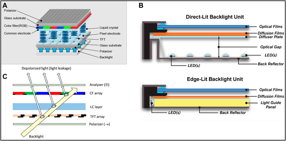
FIGURE 1. (A) Structure of LCD (Park et al., 2013), (B) direct-lit backlight unit and edge-lit; (C) schematic diagram of depolarized light generated by the LCD module, which contributes to light leakage of LCDs (Chen et al., 2017).
Figure 1B shows the structure of the backlight unit (BLU) in edge-lit and direct-lit types. LED edge-lit BLUs are composed of LED arrays placed around the screen edges for backlighting, with a light guide illuminating the entire LCD panel. Direct-lit BLUs utilize an LED matrix on the backside of the LCD module and a diffuser layer to produce homogeneous light for the LCD module. Both the aforementioned BLUs have their own benefits. The edge-lit structure has thinner profiles and is cheaper due to lesser requirement of an LED chip, while the direct-lit structure provides higher brightness, better luminescence efficiency, and potential local dimming abilities. In general, edge-lit BLUs are preferred options for mobile devices, laptop screens, and cell phones due to thickness, weight, and cost (Moon and Oh, 2015).
The low contrast ratio is the most criticized problem of LCD. The unpolarized light scattering, as shown in Figure 1C, results in the light leakage problem (Chen et al., 2017), and so the LCD cannot achieve a true dark state. The commercial VA, IPS, and TN panels have contrast ratios of approximately 5,000, 1,000, and 1,000, respectively. On the other hand, theoretically, the organic light-emitting diode (OLED) panel can reach an infinite contrast ratio.
To improve the contrast as well as the color gamut, different solutions were proposed. Mini-LED is the ultimate product of a direct-lit LED backlight LCD. Researchers and businesses have been trying to shrink LED dies and fabricate dedicated active matrixes, which are possible for backlights of future LCDs and may even be used as display panels themselves. This is where the concepts of mini-LED and micro-LED come from. We will discuss micro-LED later because it doesn’t need an LCD module anymore. By controlling each LED, each pixel can conceptually reach the true dark state and also reduce the response time. By locally controlling the on–off state of the backlight zone, a higher contrast ratio can be achieved and at the same time reduce some power consumption and expand the color gamut (Xiao et al., 2021). Furthermore, quantum dots (QDs) are also a promising technology to further improve the performance of LCDs. TCL technology announced a 4K HDR TV in 2021, using a blue mini-LED backlight and a QD film behind the LCD module, as shown in Figure 2A. Apple Inc. also announced iPad Pro 12.9 (2021) with the Liquid Retina XDR display, which utilizes a mini-LED backlight with advanced local dimming function, as shown in Figures 2B, C.
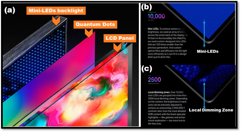
FIGURE 2. (A) Schematic of QD-mini-LED by using mini-LED and QD film from the TCL US official website. (B) Mini-LED backplane and (C) local dimming technology used in iPad Pro 12.9 (2021) from the Apple official website.
In summary, LCD was dominant because of its cheap, reliable, and acceptable performance. Mini-LED and QD are introduced for next-generation technology for LCD and they may be the solution for LCD manufacturers with few changes required in existing production lines.
Plasma Display Panels
The plasma display panel (PDP) is a member of self-emissive panel technology. Like OLED and micro-LED, the PDP controls each monochromatic subpixel by the address circuit. Each single-color subpixel of PDP was a closed cell that contain inert gases, phosphors, and electrodes for free-electron generation. The light is generated in the same way as fluorescent lamps by applying high voltage, free electrons are emitted, and then the in-cell inert gases are ionized, becoming plasma. The phosphors are excited by ultraviolet radiation from a combination of ionized gases and convert ultraviolet light to visible light (Hilsum, 2010).
The phosphors are the key component in the PDP that determine color, efficiency, and lifespan of PDP (Kim et al., 2000; Wu et al., 2007). Emission spectra of red, green, and blue phosphor materials, that is, (Y, Gd)BO3:Eu3+, BaAl12O19:Mn2+, and BaMgAl10O17:Eu2+, respectively, are shown in the figure (Kim et al., 2000). However, phosphors under the high temperature and high energy irradiation flux in a small cell are shortened (Shuxiu, 2006). Also, the PDP suffered from the notorious burn-in phenomenon, in which phosphors degrade and lose their emissive property (Suk Joo et al., 2008).
The PDP possesses a high theoretical contrast ratio as other self-emissive displays without image distortion like curved screens. Also, the PDP has a thinner profile than CCFL-LCD at that time. The PDP was once the most promising display technology of high-end and large size in the market in the 2000s (Liu, 2012). The PDP was easier to be manufactured in large size and exhibited wider viewing angle, higher color saturation, and thinner profile than LCD at that time, but all of these merits come with higher production costs (Shinoda, 2006). However, the introduction of LED as a backlight source for LCD further increased lifespan, lowered power consumption, thinned the panel profile, and least but not last removed lead content in CCFL tubes from LCD (Kakinuma, 2006). Aside from that, thin-film transistors (TFT) relived the viewing angle problem of LCD (Kim et al., 2006). Those improvements made PDP lose the edge to LCD. Apart from LCD, the emerging OLED technology exhibits simpler basic design, a wider color gamut, and the possibility for fixable displays. Eventually, the production lines of PDP around the world were successively closed before 2015 (Pansonics, 2013; Reuters, 2014).
Organic Light-Emitting Diode
In recent years, most of the commercial electronics are equipped with OLED displays, though LCD still dominates the market at this moment. The ultra-high contrast ratios owing to its self-emissive property, thinner profile, and shorter response time make it more attractive to consumers. Moreover, the flexibility of OLED is incomparable with LCD panels. Flexible OLEDs are not just “flat panel displays” anymore and thus open up the possibility for versatile applications, such as wearable and biomedical devices (Jin et al., 2016; Keum et al., 2020; Hong et al., 2021). In Figures 3A, C–E, flexible and transparent OLED fabricated on a PET thin film was reported (Choi et al., 2020).
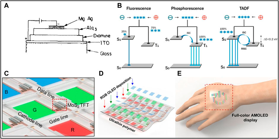
FIGURE 3. (A) Structure of the first OLED with an Mg/Ag alloy with a molar ratio of 10:1 as the cathode, Alq3 as the emissive layer, diamine as the hole transport layer, and an ITO-coated glass substrate as the anode (Tang and VanSlyke, 1987). (B) Scheme of mechanism for fluorescence, phosphorescence, and TADF (Pode, 2020). (C)Schematic diagram, (D) deposition illustration, and (E) photo of full-color AMOLED fabricated on a 6-µm PET thin film and powered by two-dimensional MoS2 transistors with single-pixel that was connected with the gate line, the cathode line, and a MoS2 transistor (Choi et al., 2020).
The first practical OLED debuted in 1987 by Tang and VanSlyke (1987), which had a forward voltage as low as 2.5 V, while at that time other organic electroluminescence devices needed driving voltage around 100 V (Williams and Schadt, 1970; Williams et al., 1972; Vincett et al., 1982). Simple fabrication, fast response, and high electroluminescence efficiency also attracted wide attention.
The organic emissive layer is the key part of OLED as it determines its optoelectronic properties as well as limitations and thus, has been widely investigated. Several kinds of materials are proposed and reported. Briefly, the emissive materials are categorized into three different generations. The first generation is the fluorescent materials such as the aforementioned Alq3 developed in the 1990s. These fluorescent materials suffer from low internal quantum efficiency as statistically only 25% of singlet excitons can be generated after excitation (see Figure 3B) (Friend et al., 1999; Pode, 2020). The phosphorescent materials incorporated with expensive metal elements, such as Ir, OS, and Pt, enable OLED to reach almost 100% internal quantum yield by intersystem crossing (Adachi et al., 2001), and the extraordinary light-emitting performance realized in the second-generation OLED (Hong et al., 2021). The third-generation OLEDs are made of thermally activated delayed fluorescence (TADF) materials. The delayed fluorescence was first observed in 1961 by Eosin, while the breakthrough was made around 2010 when Adachi et al. (2001) utilized this phenomenon to harvest the triplet states by reverse intersystem crossing as demonstrated in Figure 3C. This resulted in nonemissive recombination and realized the high-efficiency TADF OLED. The TADF materials exhibited no more reliance on expensive metal elements and no sacrifice of internal quantum efficiency was observed. While the internal quantum yield of OLED can achieve almost 100% (Baldo et al., 1998), the external quantum yield of commercial OLED is approximately 20% only, due to light extraction problems in structure (Salehi et al., 2019). The disadvantage of OLED is its lifespan (So and Kondakov, 2010) and furthermore different degradation rate for red, blue, and green pixel causes color shift and image sticking (Jang et al., 2016; Yin et al., 2019). Thus, scientists are working on not only exploring novel emissive materials but also developing aging compensation technology to deal with these issues (Volkert et al., 2015).
There are two mainstream structure designs in the market: active-matrix OLED (AMOLED) and white OLED (WOLED), as demonstrated in Figure 4A and Figure 4B, respectively. Figures 4D, E suggested that AMOLED in Samsung Galaxy S10 has the narrower FWHM, contributing to a wider color gamut, over WOLED in TV, but large size and ultra-high-resolution AMOLED is subjected to a complicated fine metal mask process. Large-sized fine metal masks are challenging to fabricate into the large size and align to an accurate position (Chen and Chen, 2016; Kim et al., 2020). Figure 4C shows a color conversion design using a blue OLED and color conversion materials, but color filters might be needed to absorb excess blue light. QDs are exceptional color conversion materials to realize the QD-OLED, which was announced by Samsung in CES 2022 (Sag, 2022).
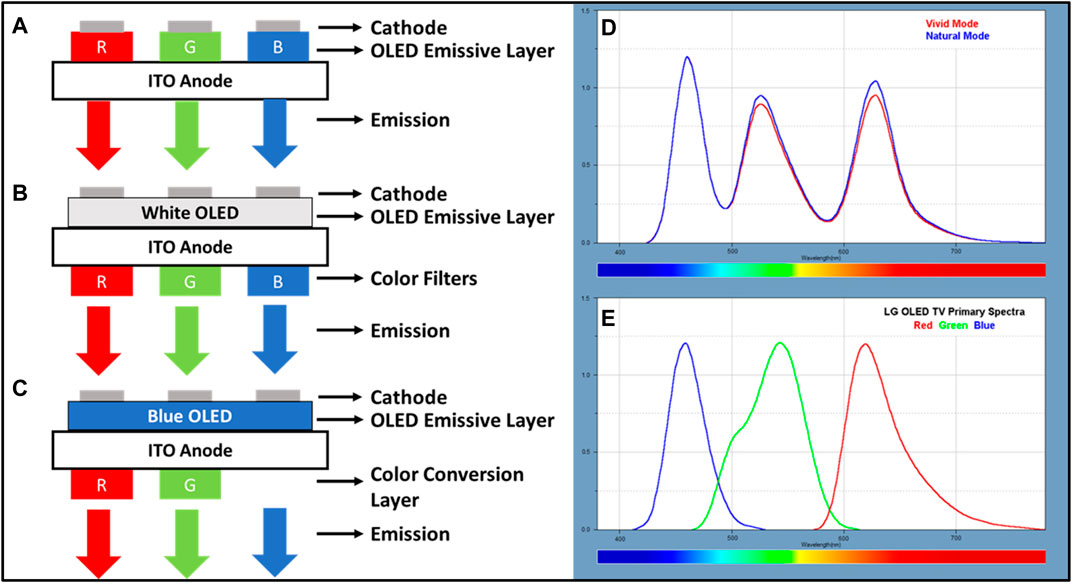
FIGURE 4. Full-color structure of (A) RGB OLED, (B) WOLED, and (C) color conversion OLED (Yin et al., 2019). Spectra of (D) AMOLED on Samsung Galaxy S10 (Displaymates, 2019) and (E) WOLED on LG OLED TV (Soneira, 2017).
LED Matrix/Array
LED is a well-known and commonly seen solid-state luminescence nowadays that exhibits several advantages over traditional light sources, such as lower maintenance cost, higher efficiency, and smaller size (Li et al., 2020). LED was first introduced in 1927 by the Soviet scientist Losev (1927) and Zheludev (2007). He made a contact between a metal wire and silicon carbide and measured the current–voltage properties as well as the emission spectra of the device. Yet, after several decades, in 1993, Edmond and colleagues reported a 6H-SiC single junction LED with an efficiency of only 0.02–0.03%. The efficiency of SiC LED has not increased much due to its indirect bandgap. LED is a p-n junction diode. The recombination is either radiative or nonradiative, which is related to the nature of direct or indirect bandgap semiconductors. In direct bandgap semiconductors, recombination emits photons (radiative), while in indirect bandgap semiconductors, the electron undergoes energy and momentum changes, so the energy is released as a phonon (heat and nonradiative) along with photon (light and radiative), as shown in Figures 5A, B(Kasap and Sinha, 2013). Nevertheless, nonradiative recombination can never be eliminated in the real world.
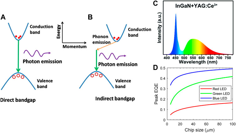
FIGURE 5. Comparison of direct (A) and indirect (B) bandgap behaviors when there is exciton recombination (Kasap and Sinha, 2013). (C) Structure of high efficient double-heterostructure blue LED fabricated and published in 1994 (Nakamura et al., 1994). (D) Emission spectrum of a white LED is fabricated by a blue LED chip with YAG: Ce phosphor (Schubert, 2006).
After decades of modifications to materials, equipment, and structures, Nakamura et al. (1994) fabricated a high-luminescence InGaN blue LED with a double-heterostructure in 1994, which was inspired by Nobel physics laureates in 2000, Zhores Ivanovich Alferov and Herbert Kroemer (Nakamura, 2015). In 2014, Shuji Nakamura, Isamu Akasaki, and Hiroshi Amano were awarded the Nobel Prize in Physics for the invention of efficient blue LED. The application of LED in the display industries is mainly for the backlights of LCD panels. The color gamut of LCD would be affected by the spectrum of backlight and transmission of color filters. The white light is normally generated by a blue LED chip with phosphors which is normally yttrium aluminum garnet with Ce3+ dopant, normally named YAG: Ce, as shown in Figure 5C. However, the low contents of blue and red colors in the spectrum of YAG: Ce are insufficient to cover the visible color space, thus resulting in the low color gamut of LCDs. To expand the color gamut, some solutions were proposed such as the addition of red KSF phosphor.
LED matrix/arrays can be used as display panels but only for applications with low pixel density requirements, such as outdoor displays, LED walls, digital displays, and message boards, etc. For example, in an LED matrix made from 512 RGB LEDs, each chip having red, green, and blue dies with a pitch distance of 6 mm has a pixel density of 4.2 per inch, which is nowhere near as high as the pixel density of display panels used on smartphones, laptops, and monitors. Nevertheless, scientists and businesses are now working on shrinking LED chips, allowing for the development of a high-resolution LED matrix display and this is the origin of the micro-LED, which will be discussed next. Micro-LED is the hottest topic in current years, both in academic as well as the industries, because it is the most promising display technology to compete with, or even overwhelm OLED. The concept of micro-LED is somewhat similar to OLED, which uses a single chip with a size smaller than 100 μm to make a single subpixel (a pixel composes of red, green, and blue subpixels). This means no more reliance on LCD modules and thus making it free from the disadvantages of LCDs. In theory, micro-LEDs exhibit self-emission, high ambient contrast, and simple structures, the same as OLEDs and beyond that, they have a longer lifetime and less power consumption. In comparison with current LCDs, micro-LED and OLED both produce a higher contrast ratio, less power consumption, faster response, and a wider viewing angle. (Huang et al., 2020).
The full-color methods of micro-LEDs were proposed as illustrated in Figures 6A–C. The RGB micro-LED suffers from the low luminescence efficiency of red LEDs in micron-scale, complex fabrication processes (Figure 6D), lattice mismatch due to the composition difference of RGB LED and buffer layer (Wu et al., 2018). The color-conversion is a method to colorize micro-LED and has the advantage of a simpler process and circuit design. The key point for the color conversion is the material used, and QDs are a promising candidate, which will be discussed in the later section.
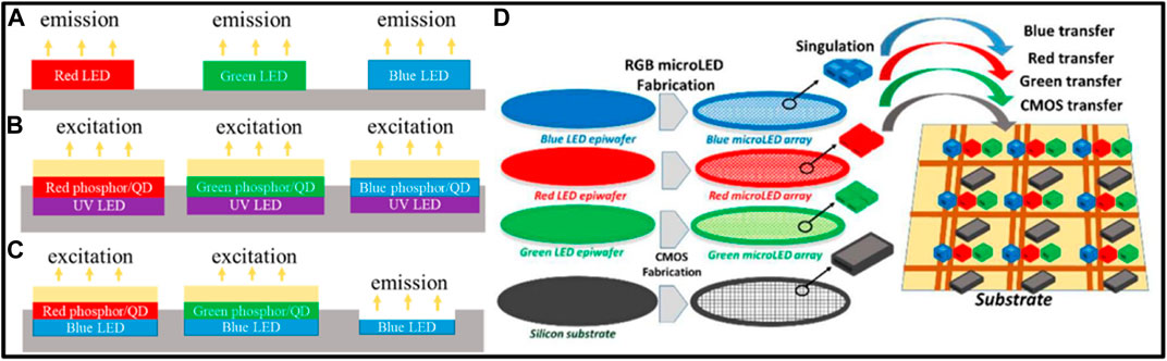
FIGURE 6. Full-color micro-LED. (A) RGB micro-LED, (B) color-conversion UV-based micro-LED, and (C) color-conversion blue LED-based micro-LED (Wu et al., 2018). (D) Scheme of the fabrication process of RGB micro-LED (Happich, 2019).
Although micro-LED gets several advantages, there are still some obstacles to practical application. First, as shown in Figure 5D, the efficiency of LED decreases markedly, when LED was downsized due to the sidewall effect (Wong et al., 2018), especially for the red chips (Wong et al., 2020). Second, the mass transfer is challenging (Linghu et al., 2021). For example, approximately 6.2 million LED dies are needed for a display panel with a resolution of 1920 × 1,080. Many design structures of micro-LED panels have been proposed. The most ideal one is downsizing red, blue, and green LEDs to be isolated subpixels, but as the driving voltages of red, green, and blue chips are different, this leads to the design of the control circuit and panel to be more arduous. To solve this issue and simplify the design, another micro-LED was proposed with every subpixel made from blue LED chips. The driving voltage of the micro-LED control circuit is unified, and the low red LED chip is removed, increasing the power efficiency of micro-LED displays. Yet, the color conversion by traditional phosphors is impractical due to the insufficient absorption area (Liu et al., 2020c), which mainly originated from the comparable size of phosphors to micro-LED chips, and the quantum dots were proposed as an alternative solution (Yang et al., 2019; Wang et al., 2020). Quantum dots, such as CdSe and perovskites, exhibit high absorbance for light with radiation energy lower than its bandgap. The 99% absorption, optical density (OD) of 2, of blue light can be achieved by CdSe/CdS and CsPbBr3 with a thickness of 5 µm and volume ratio of 20–30%. With the high absorption of blue light, color filters for excess blue light removal can possibly be removed from the micro-LED structure (Osinski and Palomaki, 2019). Aside from color filters, distributed Bragg reflectors (DBR) were proposed as a solution that reflects blue excitation from the blue LED chips for QDs to absorb it (Kakinuma, 2006; Lin et al., 2017).
Brief Introduction to Quantum Dots Application for Displays
The increasing production capacity of larger, cheaper, and superior performing OLED panels are gaining the market share over traditional LCDs. Figure 7 suggested two setups of LCD using quantum dots; the LCDs equipped with quantum dot enhancement film (QDEF), as shown in Figure 7B, can be a solution for LCD with minor changes in manufacturing streamlines. It was reported that by introducing QD film, NTSC was achieved at 107% as opposed to 70% originally (Shahjahann and Akter, 2018). Figure 7C reveals another solution to LCD by fabricating the color filter with quantum dots, which would alter some streamline processes, but can reduce the thickness and cost of an additional film. Both solutions can be applied for mini-LED because theoretically, they are the same structure as a direct-lit LCD structure. Mini-LED incorporated with quantum dots can have a larger gamut, purer color, and higher contrast than traditional LCD. Although, the color gamut expanded, the bulky and stiff structure of the LCD module limits their further application. Moreover, micro-LED was introduced as a more promising next-generation display, and phosphors have reached their limit for downsizing, so the quantum dot seems indispensable to color conversion in micro-LED (Liu et al., 2020c).
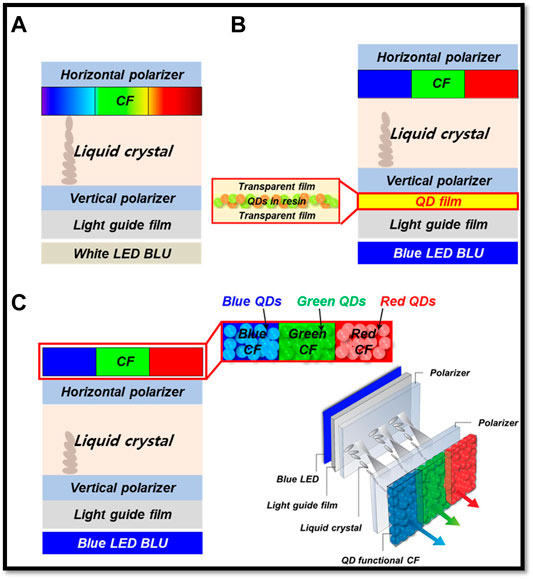
FIGURE 7. Perovskite QD backlight device fabrications and LCD performance. (A) LCD structure with color filter (CF), (B) PQD-enhanced thin films incorporated between light-guided films and vertical polarizer, and (C) white light generation due to color conversion phenomenon of PQD EFs (Ko et al., 2018).
Roles of Perovskite Quantum Dots in Next-Generation Displays
The degrees of freedom in dimension affect the band structure of a material. Figure 8A reveals the density of state in different dimensions and it illustrates the atomic-like quantized energy level, which contributes to the tunability of optoelectronics properties in quantum dots when their sizes are varied. Quantum nanomaterials are mainly semiconductor materials of nanoscale dimensions and can be further classified as zero- dimension to two-dimension. The zero-dimension nanomaterial is the so-called quantum dot, the one-dimension nanomaterial is the quantum wire, and the two-dimension nanomaterial is denoted as the quantum well. Beyond the zero-dimension to two-dimension material, they are called bulk materials (Figure 8B).
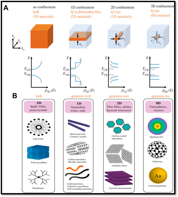
FIGURE 8. (A) Density of state (Edvinsson, 2018) and (B) examples (Poh et al., 2018) of bulk, 2D-nanoplate, 1D-nanorod, and 0D-quantum dot.
The semiconductor quantum dots can be fabricated by chemical vapor deposition (Sun et al., 2012), physical vapor deposition (Alkhatib and Nayfeh, 2013), molecular beam epitaxy (Franchi et al., 2003), and solution method, etc. Among them, the solution-processable quantum dots attract attention because it enables potential applications such as inkjet printing (Huang et al., 2019) and does not require CVD, PVD, and other complicated systems. The general synthesis route for semiconductor nanocrystals is the hot injection method (De Mello Donegá et al., 2005). Figure 9A illustrates the rapid nucleation and the further growth along with the reaction time via the hot injection method. The hot injection is performed in stabilized coordinating solvent under inert gas with reflux and proper heating, as shown in Figure 9B.
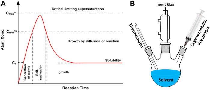
FIGURE 9. (A) Kinetic and growth of nanocrystal of semiconductor crystals and (B) the hot injection setup (Murray et al., 2000).
For the display backlight applications, colloidal semiconductor quantum dots take advantage of their wide absorption band, narrow emission, facile synthesis, high quantum yield, and tunable emission. We will discuss three of the most reported quantum dots for color conversion and display application: CdSe, InP, and Perovskite.
CdSe Quantum Dots
A well-shielded CdSe quantum dot exhibits approximately 30 nm full width at the half maximum (FWHM) and PLQY of above 90%. The central emission wavelength of CdSe quantum dots can be modulated by particle size and cover the whole visible light range, as shown in Figures 10A–C.
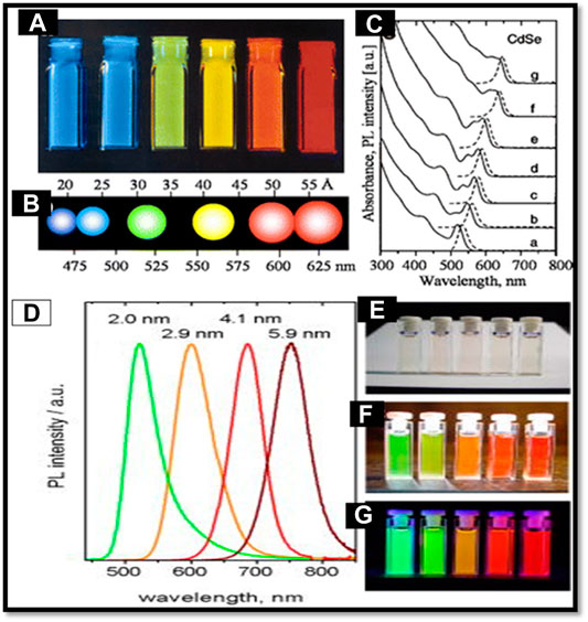
FIGURE 10. (A,B) Image of CdSe QDs with different particle sizes and (C) their size-dependent absorption and emission spectrum (Biju et al., 2008). (D) Spectrum and images of InP QDs under (E) ambient conditions, (F) white light, and (G) 366 nm UV light (Adam et al., 2005).
Nevertheless, the first problem is the toxicity of cadmium content. Restriction of Hazardous Substances in Electrical and Electronic Equipment (RoHS) limited the progress of CdSe quantum dots. Second, the well-contrasted core–shell structure of CdSe is indispensable. The CdSe/CdS/ZnS (Talapin et al., 2004), CdSe/ZnSe/ZnS (Talapin et al., 2004), CdSe/ZnSe (Reiss et al., 2002), CdSe/CdS, CdSe/ZnS/CdS/ZnS (Linkov et al., 2016), and other core–shell structures were reported with PLQY of 80%, 80%, 60–85, 50, and 100%, respectively. Without the shell passivation, PLQY of CdSe quantum dots tumbles dramatically, and the delicate core–shell structures complicate the production route.
InP Quantum Dots
InP quantum dots serve as a less toxic alternative to CdSe quantum dots. Especially after the prohibition of cadmium in the European Union was imposed, the cadmium-free substitute became inevitable. The well-passivated InP quantum dots were reported with PLQY of approximately 70% and FWHM below 40 nm (Chen et al., 2020). The central emission wavelength covers from green to red, which is suitable for down-conversion, as shown in Figures 10D–G.
Similar to the CdSe quantum dots for InP also, delicate shell passivation is needed to ensure high photoluminescence properties. The rigid requirement in the hot injection synthesis makes the synthesis time-consuming. Some more convenient synthesis routes were reported, for example, the InP/ZnS quantum dots with FWHM of 40–60 nm and PLQY of 50–70% fabricated via one-step synthesis by Li, Liang, and Reiss, Peter (Li and Reiss, 2008). Apart from the complex synthesis route, the phosphorus source, tris(trimethylsilyl) phosphine, is costly. Bang et al. (2017) reported an inexpensive, red phosphor powder, an alternative phosphorous source, but the fabricated InP/ZnS quantum dots were with a lower PLQY of 60% and the broadened FWHM of 70 nm. However, the delicate controlled environment, including the inert atmosphere and high temperature (up to 300°C), still are required, and this hampers the scale-up for industrial application (Chen et al., 2020).
Perovskite Quantum Dots
The perovskite quantum dots exhibit the general ABX3 structure, where the most-investigated A-site cations are methylammonium, formamidinium, and cesium ions, the B-site cation is lead, and the X-site anions are chloride, iodide, and bromide ions. The chemical structure and transmission electron microscopy images of perovskite quantum dots are shown in Figures 11A, B (Du et al., 2017). The perovskite quantum dots with organic A-site cation are commonly called hybrid perovskite quantum dots, while the ones with the inorganic A-site cation are named inorganic or all-inorganic perovskite quantum dots.
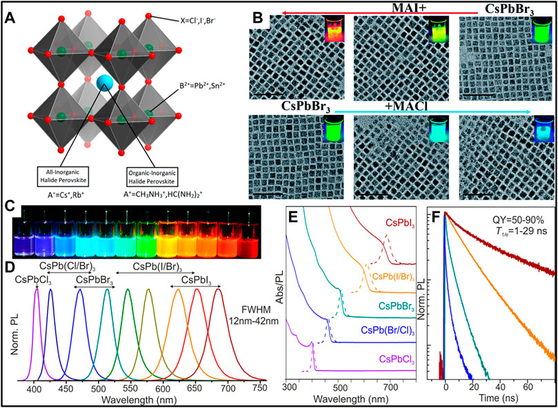
FIGURE 11. (A) Structure of perovskite. (B) TEM image, (C) photo, (D) photoluminescence spectra, (E) absorption spectra, and (F) time-resolved photoluminescence of perovskite quantum dots (Protesescu et al., 2015).
The perovskite quantum dots exhibit excellent luminescence properties. It is reported that perovskite quantum dots possessed nearly 100% PLQY and FWHM as narrow as 20 nm (Xu et al., 2020). The perovskite quantum dots exhibit high quantum yield and narrow FWHM without shelling, while for both InP and CdSe QDs, the delicate core–shell is required. Both organic and inorganic halide perovskites were reported with high defect tolerance, and the normal intrinsic defects would only form shallow traps that affect their optoelectronic properties (Steirer et al., 2016; Kang and Wang, 2017). The inorganic perovskite quantum dots CsPbX3 (X = Cl, Br, I) were first synthesized in 2015 via the hot injection method. The emission can be modulated by tuning the content of different halide anions from blue to red covering the whole visible spectra, as shown in Figures 11C–E. Lifetime was mainly used for investigation the charge-carrier dynamics (Figure 11F).
The Properties of Perovskite Quantum Dots
The ionic nature is the most distinguished property of halide perovskite from other semiconductor quantum dots, which normally are with strong covalent bonds. This offers perovskite quantum dots a different and facile route. Perovskite quantum dots can be synthesized by more facile strategies. In 2015, the ligand-assisted reprecipitate was introduced by Zhang et al. (2015). In their work, the as-synthesized hybrid perovskite quantum dots exhibited emissions covering 400–800 nm, FWHM of 20–50 nm, and PLQY up to 70%. The color-converted white LED fabricated by mixing green perovskite quantum dots and K2SiF6:Mn4+ demonstrated a color gamut of approximately 130% NTSC. The ligand-assisted reprecipitate strategy no more requires the inert atmosphere and high temperature like the traditional hot injection method. Geng et al. (2018) proposed the first water synthesis method by attentively controlling pH value. Liu et al. (2020a) reported a stable MAPbBr3@PbBr(OH) synthesized in the water, which exhibited broadened FHWM and PLQY of ∼80%. The ionic properties of halide perovskite materials, which are normal semiconductor quantum dot materials in absence of, enable the Aforementioned synthesis routes.
However, the ionic instinct also contributes to the most-criticized instability problem of perovskite quantum dots. The stability of perovskite quantum dots has been demonstrated to be affected by polar solvents (Liu et al., 2020a), which implies that the solvents used in the ligand-assisted reprecipitation method affect the stability of perovskite quantum dots. Chun et al. (2020) reported and concluded that reducing the dose of the polar solvent, dimethylformamide, used in the precursors reduces the internal defects of perovskite lattices and improves the stability of perovskite quantum dots. Water was also proposed to trigger the decomposition of perovskite quantum dots by Eq. 1 (Geng et al., 2018).
In all-inorganic perovskite, water was suggested to strip CsBr away from perovskite crystals and cause the phase transformation, as shown in Eq. 2 (Turedi et al., 2018; Du et al., 2021).
The exposure to the humidity of MAPbI3 perovskite solar cell would result in the formation of the MAPbI3⋅H2O complex. Aside from the instability of polar solvents, the perovskite quantum dots were vulnerable under photoluminescence. The phase segregation happens when the mixed halide perovskite quantum dots and this process would be accelerated under photoluminescence (Barker et al., 2017).
Figure 12A illustrates another unique property of lead halide perovskite that halide anion exchange occurs when introducing an excess of other halide species (Akkerman et al., 2015; Nedelcu et al., 2015; Yoon et al., 2016b). On one hand, researchers can make use of the tunability strategies to change emission wavelength. On the other hand, this would hinder the application in mixing. The ideal scheme is using a blue LED chip to pump red and green mixing together. Nevertheless, the mixing of red and green perovskite would not give the origin emission from both quantum dots due to anion exchange (Huang et al., 2016), as shown in Figure 12B. For display application, this means two quantum dot color filters with a spacer are needed for LCD color enhancement. Fortunately, adequate encapsulations can make perovskite quantum dots impervious to the anion-exchange effect (Sun et al., 2016).
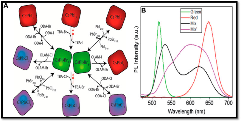
FIGURE 12. (A) Schematic diagram of paths of halide anion exchange (Akkerman et al., 2015) and (B) spectrum of the initial mixture (purple line), mixture after 5 min (black line), and green and red perovskite quantum dots (Huang et al., 2016).
To overcome the instability problem, several strategies were proposed, including doping (Liu et al., 2017), inorganic shell (Wang et al., 2018; Dirin et al., 2019), ligand passivation (Zhang et al., 2019; Lu et al., 2021; Min et al., 2022), polymer matrix (Liu et al., 2020b). Liu et al. (2017) doped the aluminum into perovskite quantum dots and fabricated the white LED that displays 116% NTSC. Tang et al. (2019) reported a CsPbBr3@SiO2 doped with Mn2+ that demonstrated better stability than pristine CsPbBr3. Pan et al. (2020) demonstrated the reverse micelles by first up talking lead halide on the amino groups of poly 2-(dimethylamine)ethyl methacrylate (PDMAEMA) and self-assembly by injection into a nonpolar solvent. As the reverse micelles formed, the CsBr was introduced, and slowly diffused into the copolymer, forming CsPbBr3. The polar solvents were deterred by hydrophobic aminopropylisobutyl POSS (ap-POSS), and thus the stability increased (Pan et al., 2020). Chen et al. (2018) synthesized the CsPbBr3/Cs4PbBr6 composite with superior stability and higher PLQY than pristine CsPbBr3.
Perovskite Quantum Dots in Backlight Display Application
Perovskite light-emitting diodes have the advantages of high luminous efficiency, and color purity, and the emission wavelength is continuously adjustable in the visible light range. The development of green perovskite light-emitting diodes, the basic structure of perovskite materials and light-emitting diode devices, and the improvement of the efficiency of perovskite light-emitting diodes for backlit are mainly introduced in this section. Backlit displays are generally assembled by green PQDs and red PQDs upon blue LEDs. PQDs are used to encapsulate with polymers to prepare thin films or sheets (PQDs enhanced film). Polymerized to polymethyl methacrylate (PMMA) after being combined with the quantum dots, the thermal stability of PQDs was enhanced. On the other hand, PMMA with PQDs shows excellent compatibility and may be customized through the prepared mold in the desired shape. In addition to PMMA, it can be isolated from external oxygen and moisture, oxidation mitigation quantum dots, thereby improving the environmental stability of the perovskite quantum dots (Xin et al., 2018). An epoxy resin or UV glue is also commonly used for the packaging of the QDs (Wei et al., 2019).
To improve the color gamut, color purity, and rendition of LCD, PQDs have been regarded as marginal to traditional phosphor-based color converters in the backlit-based display devices. Liquid crystal displays (LCDs) have recently been enhanced by quantum dot enhancement films (QDEFs) in conjunction with LED backlight units (BLUs). The Park group demonstrated the superiority of the LCD by using functional enhancement thin films (QDEFs) made from green (G), red (R), and blue (B) PQDs and linked with a blue LED BLU (Ko et al., 2018). According to (Figures 7A–C), conventional CFs, QDEF, and QD functional CFs were inserted into a polarizer microscope by laying a blue LED on top of a BLU array. A conventional or QD functional CF is directly stacked vertically on top of the LCD along with a blue-LED, light-guide film, vertical polarizer (HP), twisted liquid crystals (TWC), and horizontal polarizer (HP). After that, a polarizer microscope was used to estimate the FWHM and QY of the polarized blue, green, and red PL spectrums. PQD’s functional CFs combine with a blue-LED to create a polarized spectrum of polarized light, which maximizes the display’s color gamut and achieves a world record of over 102.70% (137.0%) of Rec. 2020 (NTSC) standard performance. Such a color gamut improvement could theoretically lead to super ultrahigh-resolution LCDs with an unlimited scaling-down capability. Additionally, it has been predicted that PQDs will improve the color gamut of LCDs by replacing their traditional phosphor color converters. The inherent ionic crystal feature and the low formation energy of perovskite halide materials cause them to usually degrade upon exposure to external stimuli (such as light, moisture, and heat), as well as cause color separation in mixtures with different compositions (Guo et al., 2021; Ma et al., 2021). Perovskites are highly sensitive to both moisture and the environment, and these issues have recently been addressed by many researchers. Various methods, for example, defect passivation, dense layer encapsulation, and embedding in different matrix components such as polymer-matrices, inorganic electrolyte salts, zeolite-Y, and silica-based matrix, have all been successfully developed to increase the stability of PQDs (Peña-Rodríguez et al., 2021; Si et al., 2021; Yao et al., 2021; Zhou et al., 2021). But their practical applications are hindered by the obstacles of aggregation, quenching, and structural instability of the PQDs. To overcome this problem Chen et al. encapsulated the CsPbX3 (X = Br, Br/I) PQDs inside glass to produce nanocomposites with superior optical performance and stability (Lin et al., 2021).
As a significance, CsPbBr3@glass has the highest PLQY of 100% due to the physical dilution approach utilized to reduce the apparent value to an intrinsic one, while the glass network ensures exceptionally high photostability and water and heat resistance. Figures 13A, B shows the assembly backlight unit that produces bright white light at 3.3 V. To create the combined white-light luminescence, this voltage is applied to the blue LEDs, which are further excited by the yellow film. Tricolor, narrow band EL emissions have occurred at 450 nm (blue LED chips), 518 nm (green CsPbBr3@glass), and 630 nm (red CsPbBr1.5I1.5@glass) at the corresponding wavelengths (Figure 13D). By comparison, the traditional backlights typically include blue LED chips and yellow Ce: YAG phosphors with wide-band emission (Figure 13C). To demonstrate this concept, a wide color gamut display (Figure 13E) was successfully demonstrated using a wide color gamut LCD panel backlit by the present CsPbX3@glass@PDMS yellow film paired with blue LED chips on the light guide plate. A single-chip microchip and an integrated circuit (IC) can be used to modulate and control input images. Display performance differences between real LCD prototypes can be intuitively observed (Figures 13F−I). Comparing the CsPbX3@glass@PDMS assembly backlight to the commercial ones, the LCD screens adopted by the LCD industry are exhibiting more details of colored objects. The commercial backlight unit displays a yellowish-green color on its screen (Figure 13F), while the assembly backlight unit displays a pure green color on its screen and can more effectively reproduce colors (Figures 13H–I). Using the CsPbX3@glass@PDMS film as a backlight, it is possible to display red color in a pure form with a high saturation (Figure 13I). The color gamut of assembled backlight displays was compared with those of NTSC 1953 standard and commercial backlight displays. Using CIE color coordinates, it was calculated that assembly backlight displays had a color gamut of 103% of NTSC 1953 and 152% of the commercial backlight displays (Figure 13J). After the backlight was lighted for 48 h, the EL spectrum was recorded to test the stability of the CsPbX3@ glass@PDMS backlight. Based on Figure 13K, EL intensities had nearly come to a standstill, despite blue, green, and red tricolor emissions remaining stable. After continuously operating the LCD devices for 48 h (insets of Figure 13K), the (green, red, and white) luminance remains unchanged.
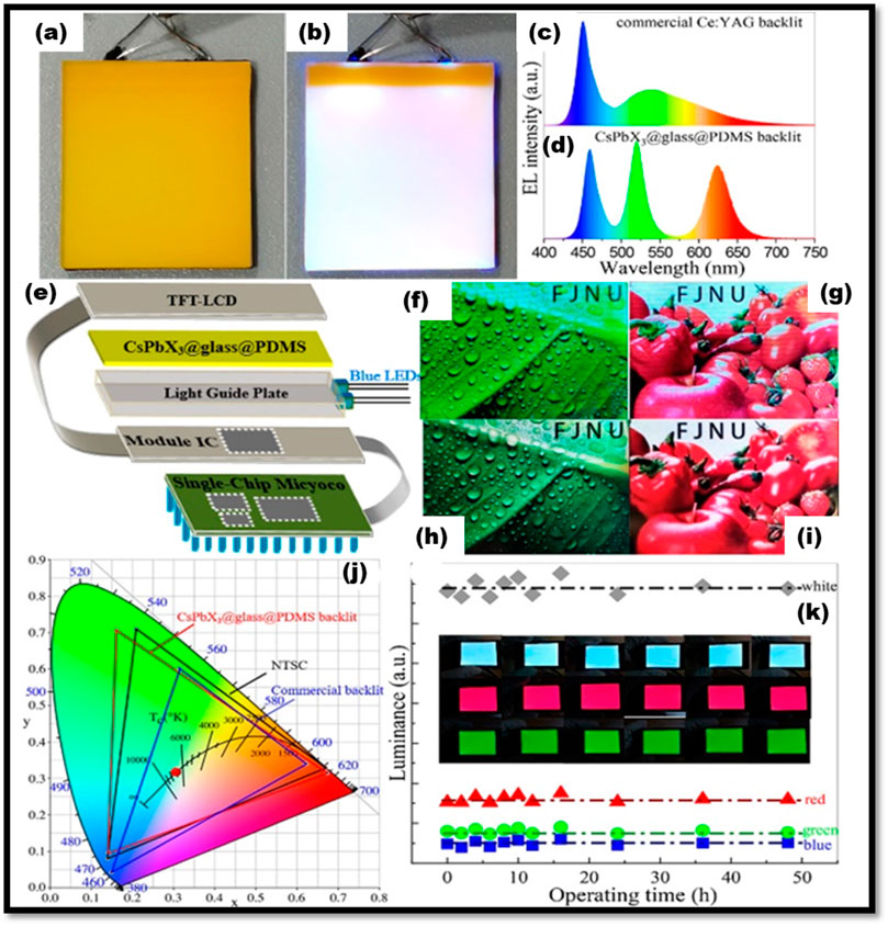
FIGURE 13. Demonstrations of the CsPbX3@glass@PDMS film-based backlight unit with the size of 4 cm × 6 cm. (A) Under daylight and (B) under 3.3 V applied voltage. EL spectra of white backlight units using blue LED chips with (C) Ce: YAG yellow phosphor and (D) CsPbX3@glass@PDMS film. (E) Schematic illustration of LCD device structure using the as-prepared backlight unit. Display performance of the LCD screen with the (F,G) commercial backlight unit and (H,I) CsPbX3@glass@PDMS film backlight unit. (J) Color gamut of the commercial screen (blue line), the CsPbX3@glass@PDMS film screen (red line), and NSTC 1953 standard (black line) in the CIE diagram. (K) Variation of luminance of LCD devices with continuous operating times up to 48 h. Insets are the corresponding working green, red, and white LCD devices (Lin et al., 2021)
On the other hand, the Young group proposed that a PQD-based six-color display system that reproduced true-to-life spectral distributions with high fidelity, widen the color gamut, and close the cyan and yellow gap in the RGB tricolored display by adding cyan (Cy), yellowish-green (Yg), and orange colors (Or) (Yoon et al., 2016a). They successfully synthesized narrow bandwidth and highly efficient fully inorganic CsPbX3 PQDs using a facile hot injection method. To obtain different six colors of CsPbX3 PQDs, they employed a synthetic method of scheming the ratio of halide (X) composition, which was a suitable means of shifting the emission wavelength of CsPbX3 PQDs. Furthermore, the authors demonstrated monochromatic down-converted light-emitting diodes (DC-LED) based on CsPbX3 (X = Cl, Br, I, or their halide mixtures; Cl/Br and Br/I), incorporating PQDs with UV-curable binders and long-wavelength-pass-dichroic filters (LPDFs) (see Figure 14). As shown in Figures 14A, E CsPbX3 PQD-based monochromatic DC-LED equipped with Cy, G, Yg, Or, and R emitters provides luminous efficacy (LE) values of 81, 184, 79, 80, and 35 lm/W, respectively, at 20 Ma. Also, they verified that future field-sequential-color liquid crystal displays that use white LEDs with six colors can be illuminated by color-by-blue backlights, as well as six-colored light-emitting devices that have excellent color performance and vision (see Figures 14C, D). Six-color multi-package white LEDs were fabricated with a color rendering index of 96 and a special color rendering index for red (R9) of 97 at a correlated color temperature of 6,500 K, and a wide color gamut of 145% covering the NTSC up to 1931-CIE color coordinate standards as shown in Figure 14E.
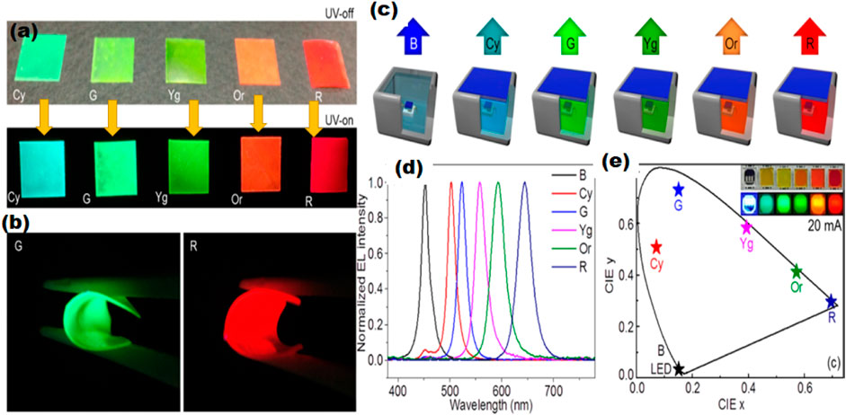
FIGURE 14. (A) CsPbX3 PQD polymer films with various halide under ambient light and under UV light. (B) CsPbBr3 and CsPb(Br0.35I0.65)3 PQD flexible sheet under UV light irradiation, (C,D) different light emission of blue-chip, PL spectra, and (E) CIE spectra of CsPbX3 PQD.
They have successfully synthesized narrow bandwidth and highly efficient fully inorganic CsPbX3 PQDs using a facile hot injection method with a two-step heating process, followed by thermal quenching. To obtain variable color emissive CsPbX3 PQDs, they employed a synthetic method of controlling the ratio of halide composition, which is a suitable means of shifting the emission wavelength of CsPbX3 PQDs. Most of the perovskite QDs fabricated via the hot injection method. This method took a long time and high temperature. The hot injection process is very sensitive also so it is very difficult to handle. To overcome this problem LARP method was also adopted by our group to bulk production of PQDs within short periods.
The perovskite-based backlight has excellent performance but still, there is a restriction for the commercialized Pb-based perovskite devices due to toxicity issues with lead contains and bulk production of PQDs. To overcome these problems many types of research have been carried out recently. But with 100% lead-free perovskite backlights performance was not good enough for the commercialization of the optoelectronic devices. Our research group recently worked on the lead-less PQDs in which Pb2+ was replaced by non-toxic elements such as Co2+, Sn2+, Mn2+, and Zn2+. Figures 15A, B show the CoCl2 and SnCl2 incorporation in place of PbBr2 to reduce the toxicity of the green PQDs (Singh et al., 2021a). With the incorporation of CoCl2 and SnCl2 into MAPbBr3 PQDs, the optical bandgap continuously increases and the bright green color changed into the canyon because of the lower ionic radii of CoCl2 and SnCl2 than PbBr2(Singh et al., 2020). For the lead-less PQDs based backlight, our group reported the color gamut up to 138% for the Co-doped and 124% of the standard NTSC for the Zn-doped PQDs (see Figure 15E) (Singh et al., 2021b). Currently, our group is developing an easy method to manufacture CH3NH3Pb1-xMnxI3 (x = 0 to .60M) PQDs under room temperature that minimizes environmental toxic waste and makes it commercially viable (Singh et al., 2019). The PQDs demonstrated strong color tunability from red to orange in response to Mn2+ inclusion concentrations ranging from 0 to 60% as shown in Figures 15C, D. The absorption energy bandgap diagram for different concentrations of Mn-doped MAPbI3 PQDs. With the increasing of the Mn concentration the energy bandgap continually increased because of the lower radii of Mn than the Pb element. For CH3NH3PbI3 without substitutes, we observed PLQYs of 98% and PLQYs of >50% for PQDs containing 15% Mn2+. The average lifetime of PQDs was found to shorten with increasing Mn2+ replacement. We demonstrate a white LED prototype by employing the CH3NH3Pb1-xMnxI3 (x = 0.15) PQDs with green QDs on a blue LED chip. The CRI and CCT values varying from 92 to 80 and 5,100–2,900 K, respectively, indicate the usability of the Mn2+ substituted PQDs as efficient warm white LEDs with a promising CRI and good stability as shown in Figures 15F–H. For most of the lead-less perovskite, up to 20–30% replacement of Pb by non-toxic divalent elements.
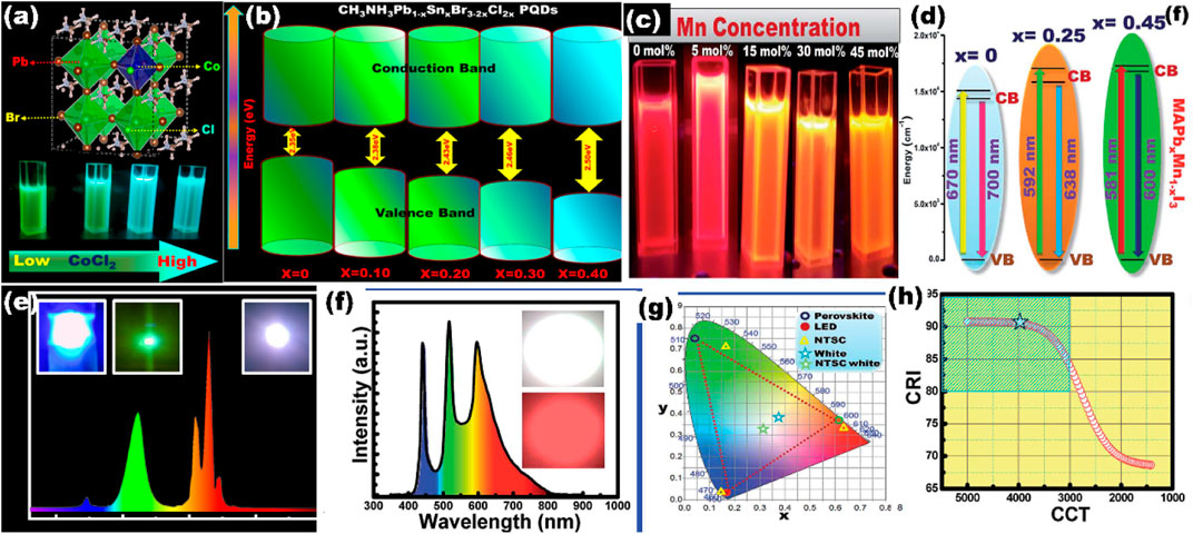
FIGURE 15. Different Pb-less PQD-based backlight LEDs, (A) MAPb1-xCox (Br/Cl)3 (x = 0–0.50) PQD structure, and its change in color from green to cyan with CoCl2 incorporation into MAPbBr3 (Singh et al., 2021a), (B) MAPb1-xSnx (Br/Cl)3 (x = 0–0.50) PQD energy band diagram (Singh et al., 2020), (C,D) MAPb1-xMnxI3 PQD colloidal solutions under UV light and energy band diagram (Singh et al., 2019), (E) white LED full spectra of MAPb1-xZnxBr3 (x = 0–0.50) PQD (Singh et al., 2021b), and (F–H) MAPb1-xMnxI3 (x = 0–0.60)PQD-based red LEDs, full-color emitter, CIE spectra, and CRI, and CCT value of the PQD-based backlight light convertor (Singh et al., 2019).
Summary and Future Prospects
In summary, metal halide perovskite quantum dots have the potential to become the core luminescent material for next-generation displays and lighting devices due to their excellent optoelectronic properties and solution processability. Ultra-high color purity, the ultra-wide color gamut of PQDs has the potential to become the core material for display devices. But still, there are many challenges toward the commercialization of PQD devices which are as follows:
1. The main obstacle is their stability issue, which includes instability under oxygen, moisture, heat, and photo-irradiation; liability for quenching in powder form; and color segregation of different composition mixtures. Many efforts had been tried to stabilize the PQDs such as inorganic coating, polymer encapsulations, and ligand exchanges. But, such kinds of approaches affected the performances of the PQDs and modified the morphologies of PQDs. Thus, there is a need to develop suitable encapsulating materials and approaches for stabilizing the PQD devices that do not reduce the performance of the original PQD device.
2. The toxicity issues due to presence of toxic Pb pose big challenges in commercializing the PQD-based devices. Although various Pb-substitutes were investigated to reduce the toxicity of the perovskite materials, these nontoxic substitutes significantly reduce the performance of the backlight devices. Moreover, the stability issue still persists in lead-less or lead-free PQD devices. Thus, it is urgent to explore nontoxic- and nonlead-based perovskite optoelectronic materials with excellent performance. Thus, the development of nonlead perovskite luminescent materials is the only way to commercialize PQD display.
3. PQD backlights are solution-processed LED optoelectronic devices, making them an attractive and feasible choice for fabricating large-area display devices. But, PQD colloidal solutions are very sensitive to their chemical composition, and most of the PQDs are prepared via a time-consuming hot injection method and also requires high temperature. Some industry-friendly synthesis methods have also been used for the fabrication of PQDs, such as microwave synthesis, ligand-assisted reprecipitation method, and ultrasonication approach. But, using such kind of synthesis approaches did not achieve the performance comparable to the hot injection method. Hence, designing and optimizing large-scale synthesis procedures for PQDs is necessary for the industrialization of QD-based backlighting.
4. PQD backlit is fabricated on blue LED chips following the incorporation of red and green PQDs. In most cases, blue light intensity is higher than the other two colors. Because of this, in the backlit display, the blue color intensity will be high which is not good for the eye. Thus, excess blue light intensity is also a big challenge for the PQD backlight displays.
5. The blinking problem in the backlight display is a common problem. The deep study about blinking of PQD backlight suggested that PQD backlit is much better than traditional backlit display. Nonetheless, still there are possibilities to enhance the blinking issue of the PQD backlit display.
In addition to these, there are still many issues to be solved in future research. In order to meet this demand, lead-free halide perovskites must still be developed as reported previously; the FWHM of emission for most lead-free halide perovskites is wider than that of lead halide perovskites, which is unsuitable for display applications. To provide ultrahigh definition displays with narrow-band emission, it is important to develop more lead-free halide perovskites. Therefore, in terms of commercialization, lead-free halide perovskites are a suitable option for backlit applications.
Author Contributions
RS and L-HC worked equally. AS and NJ helped in writing some part regarding LEDs. JS and C-HL prepared the ideas and edited the manuscript.
Conflict of Interest
The authors declare that the research was conducted in the absence of any commercial or financial relationships that could be construed as a potential conflict of interest.
Publisher’s Note
All claims expressed in this article are solely those of the authors and do not necessarily represent those of their affiliated organizations, or those of the publisher, the editors, and the reviewers. Any product that may be evaluated in this article, or claim that may be made by its manufacturer, is not guaranteed or endorsed by the publisher.
References
Adachi, C., Baldo, M. A., Thompson, M. E., and Forrest, S. R. (2001). Nearly 100% Internal Phosphorescence Efficiency in an Organic Light-Emitting Device. J. Appl. Phys. 90, 5048–5051.
Adam, S., Talapin, D. V., Borchert, H., Lobo, A., Mcginley, C., De Castro, A. R. B., et al. (2005). The Effect of Nanocrystal Surface Structure on the Luminescence Properties: Photoemission Study of HF-Etched InP Nanocrystals. J. Chem. Phys. 123, 084706. doi:10.1063/1.2004901
Akkerman, Q. A., D’Innocenzo, V., Accornero, S., Scarpellini, A., Petrozza, A., Prato, M., et al. (2015). Tuning the Optical Properties of Cesium Lead Halide Perovskite Nanocrystals by Anion Exchange Reactions. J. Am. Chem. Soc. 137, 10276–10281. doi:10.1021/jacs.5b05602
Alkhatib, A., and Nayfeh, A. (2013). A Complete Physical Germanium-On-Silicon Quantum Dot Self-Assembly Process. Sci. Rep. 3, 2099. doi:10.1038/srep02099
Baldo, M. A., O'brien, D. F., You, Y., Shoustikov, A., Sibley, S., Thompson, M. E., et al. (1998). Highly Efficient Phosphorescent Emission from Organic Electroluminescent Devices. Nature 395, 151–154. doi:10.1038/25954
Bang, E., Choi, Y., Cho, J., Suh, Y.-H., Ban, H. W., Son, J. S., et al. (2017). Large-Scale Synthesis of Highly Luminescent InP@ZnS Quantum Dots Using Elemental Phosphorus Precursor. Chem. Mater. 29, 4236–4243. doi:10.1021/acs.chemmater.7b00254
Barker, A. J., Sadhanala, A., Deschler, F., Gandini, M., Senanayak, S. P., Pearce, P. M., et al. (2017). Defect-Assisted Photoinduced Halide Segregation in Mixed-Halide Perovskite Thin Films. ACS Energ. Lett. 2, 1416–1424. doi:10.1021/acsenergylett.7b00282
Biju, V., Itoh, T., Anas, A., Sujith, A., and Ishikawa, M. (2008). Semiconductor Quantum Dots and Metal Nanoparticles: Syntheses, Optical Properties, and Biological Applications. Anal. Bioanal. Chem. 391, 2469–2495. doi:10.1007/s00216-008-2185-7
Boyd, C. C., Cheacharoen, R., Leijtens, T., and Mcgehee, M. D. (2019). Understanding Degradation Mechanisms and Improving Stability of Perovskite Photovoltaics. Chem. Rev. 119, 3418–3451. doi:10.1021/acs.chemrev.8b00336
Chen, G. K. J., and Chen, J. (2016). “AMOLED Manufacture,” in Handbook of Visual Display Technology (Springer), 1779–1797. doi:10.1007/978-3-319-14346-0_212
Chen, H., Tan, G., Li, M.-C., Lee, S.-L., and Wu, S.-T. (2017). Depolarization Effect in Liquid crystal Displays. Opt. Express 25, 11315–11328. doi:10.1364/oe.25.011315
Chen, Y.-M., Zhou, Y., Zhao, Q., Zhang, J.-Y., Ma, J.-P., Xuan, T.-T., et al. (2018). Cs4PbBr6/CsPbBr3 Perovskite Composites with Near-Unity Luminescence Quantum Yield: Large-Scale Synthesis, Luminescence and Formation Mechanism, and White Light-Emitting Diode Application. ACS Appl. Mater. Inter. 10, 15905–15912. doi:10.1021/acsami.8b04556
Chen, B., Li, D., and Wang, F. (2020). InP Quantum Dots: Synthesis and Lighting Applications. Small 16, 2002454. doi:10.1002/smll.202002454
Choi, M., Bae, S. R., Hu, L., Hoang, A. T., Kim, S. Y., and Ahn, J. H. (2020). Full-color Active-Matrix Organic Light-Emitting Diode Display on Human Skin Based on a Large-Area MoS2 Backplane. Sci. Adv. 6, eabb5898. doi:10.1126/sciadv.abb5898
Chun, F., Zhang, B., Li, Y., Li, W., Xie, M., Peng, X., et al. (2020). Internally-externally Defects-Tailored MAPbI3 Perovskites with Highly Enhanced Air Stability and Quantum Yield. Chem. Eng. J. 399. doi:10.1016/j.cej.2020.125715
De Mello Donegá, C., Liljeroth, P., and Vanmaekelbergh, D. (2005). Physicochemical Evaluation of the Hot-Injection Method, a Synthesis Route for Monodisperse Nanocrystals. Small 1, 1152–1162. doi:10.1002/smll.200500239
Dirin, D. N., Benin, B. M., Yakunin, S., Krumeich, F., Raino, G., Frison, R., et al. (2019). Microcarrier-Assisted Inorganic Shelling of Lead Halide Perovskite Nanocrystals. ACS Nano 13, 11642–11652. doi:10.1021/acsnano.9b05481
Displaymate (2019). Light Spectra for the Samsung Galaxy S10. [Online]. Available: https://www.displaymate.com/Spectra_47S.html (Accessed December 24, 2021).
Du, X., Wu, G., Cheng, J., Dang, H., Ma, K., Zhang, Y.-W., et al. (2017). High-quality CsPbBr3 Perovskite Nanocrystals for Quantum Dot Light-Emitting Diodes. RSC Adv. 7, 10391–10396. doi:10.1039/c6ra27665b
Du, K., He, L., Song, S., Feng, J., Li, Y., Zhang, M., et al. (2021). In Situ Embedding Synthesis of Highly Stable CsPbBr3/CsPb2Br@PbBr(OH Nano/Microspheres through Water Assisted Strategy. Adv. Funct. Mater. 31. doi:10.1002/adfm.202103275
Edvinsson, T. (2018). Optical Quantum Confinement and Photocatalytic Properties in Two-, One- and Zero-Dimensional Nanostructures. R. Soc. Open Sci. 5, 180387. doi:10.1098/rsos.180387
Fergason, J. (1971). Display Devices Utilizing Liquid crystal Light Modulation. U.S. Patent US3731986A.
Franchi, S., Trevisi, G., Seravalli, L., and Frigeri, P. (2003). Quantum Dot Nanostructures and Molecular Beam Epitaxy. Prog. Cryst. Growth Characterization Mater. 47, 166–195. doi:10.1016/j.pcrysgrow.2005.01.002
Friend, R. H., Gymer, R. W., Holmes, A. B., Burroughes, J. H., Marks, R. N., Taliani, C., et al. (1999). Electroluminescence in Conjugated Polymers. Nature 397, 121–128. doi:10.1038/16393
Geng, C., Xu, S., Zhong, H., Rogach, A. L., and Bi, W. (2018). Aqueous Synthesis of Methylammonium Lead Halide Perovskite Nanocrystals. Angew. Chem. Int. Ed. 57, 9650–9654. doi:10.1002/anie.201802670
Guo, L., Zhang, X., Lin, M., Zhang, Y., Xu, S., Yu, T., et al. (2021). Wide Gamut white LED Device Using green CsPbBr3 Quantum Dots Glass and Red K2SiF6: Mn4+ Phosphor. Optik 248, 168156. doi:10.1016/j.ijleo.2021.168156
Happich, J. (2019). Wafer Scale RBG MicroLEDs Simplify Transfer Process [Online]. eeNews Europe. Available at: https://www.eenewseurope.com/news/wafer-scale-rbg-microleds-simplify-transfer-process (Accessed December 24, 2021).
Hilsum, C. (2010). Flat-panel Electronic Displays: a Triumph of Physics, Chemistry and Engineering. Phil. Trans. R. Soc. A. 368, 1027–1082. doi:10.1098/rsta.2009.0247
Hong, G., Gan, X., Leonhardt, C., Zhang, Z., Seibert, J., Busch, J. M., et al. (2021). A Brief History of OLEDs-Emitter Development and Industry Milestones. Adv. Mater. 33, e2005630. doi:10.1002/adma.202005630
Huang, H., Chen, B., Wang, Z., Hung, T. F., Susha, A. S., Zhong, H., et al. (2016). Water Resistant CsPbX3 Nanocrystals Coated with Polyhedral Oligomeric Silsesquioxane and Their Use as Solid State Luminophores in All-Perovskite white Light-Emitting Devices. Chem. Sci. 7, 5699–5703. doi:10.1039/c6sc01758d
Huang, B.-L., Guo, T.-L., Xu, S., Ye, Y., Chen, E.-G., and Lin, Z.-X. (2019). Color Converting Film with Quantum-Dots for the Liquid Crystal Displays Based on Inkjet Printing. IEEE Photon. J. 11, 1–9. doi:10.1109/jphot.2019.2911308
Huang, Y., Hsiang, E.-L., Deng, M.-Y., and Wu, S.-T. (2020). Mini-LED, Micro-LED and OLED Displays: Present Status and Future Perspectives. Light Sci. Appl. 9, 105. doi:10.1038/s41377-020-0341-9
Jang, Y.-H., Kim, K.-T., Lee, H.-M., Lee, J.-E., Kim, J.-H., Oh, C.-S., et al. (2016). Experimental Study for the Establishment of an Evaluation Criterion for the Image Sticking Effect in OLED TV Panels. Jnl Soc. Info Display 24, 569–575. doi:10.1002/jsid.468
Jin, J., Lee, D., Im, H.-G., Han, Y. C., Jeong, E. G., Rolandi, M., et al. (2016). Chitin Nanofiber Transparent Paper for Flexible Green Electronics. Adv. Mater. 28, 5169–5175. doi:10.1002/adma.201600336
Kakinuma, K. (2006). Technology of Wide Color Gamut Backlight with Light-Emitting Diode for Liquid Crystal Display Television. Jpn. J. Appl. Phys. 45, 4330–4334. doi:10.1143/jjap.45.4330
Kang, J., and Wang, L.-W. (2017). High Defect Tolerance in Lead Halide Perovskite CsPbBr3. J. Phys. Chem. Lett. 8, 489–493. doi:10.1021/acs.jpclett.6b02800
Kasap, S., and Sinha, R. (2013). Optoelectronics and Photonics: Principles and Practice. Second Edition. Pearson.
Keum, C., Murawski, C., Archer, E., Kwon, S., Mischok, A., and Gather, M. C. (2020). A Substrateless, Flexible, and Water-Resistant Organic Light-Emitting Diode. Nat. Commun. 11, 6250. doi:10.1038/s41467-020-20016-3
Kim, C.-H., Kwon, I.-E., Park, C.-H., Hwang, Y.-J., Bae, H.-S., Yu, B.-Y., et al. (2000). Phosphors for Plasma Display Panels. J. Alloys Compd. 311, 33–39. doi:10.1016/s0925-8388(00)00856-2
Kim, S., Berkeley, B., Park, J., and Kim, T. (2006). New era for TFT-LCD Size and Viewing-Angle Performance. J. Soc. Inf. Display 14 (2), 127. doi:10.1889/1.2176114
Kim, C., Kim, K., Kwon, O., Jung, J., Park, J. K., Kim, D. H., et al. (2020). Fine Metal Mask Material and Manufacturing Process for High‐resolution Active‐matrix Organic Light‐emitting Diode Displays. J. Soc. Inf. Display 28, 668–679. doi:10.1002/jsid.901
Ko, Y. H., Jalalah, M., Lee, S. J., and Park, J. G. (2018). Super Ultra-high Resolution Liquid-Crystal-Display Using Perovskite Quantum-Dot Functional Color-Filters. Sci. Rep. 8, 12881. doi:10.1038/s41598-018-30742-w
Koike, V., and Okamoto, V. (1999). Super High Quality MVA-TFT Liquid Crystal Displays. Fujitsu Scientific Tech. J. 3527 (2), 221–228.
Kumar, A., Bansode, U., Ogale, S., and Rahman, A. (2020). Understanding the thermal Degradation Mechanism of Perovskite Solar Cells via Dielectric and Noise Measurements. Nanotechnology 31, 365403. doi:10.1088/1361-6528/ab97d4
Lanzetta, L., Webb, T., Zibouche, N., Liang, X., Ding, D., Min, G., et al. (2021). Degradation Mechanism of Hybrid Tin-Based Perovskite Solar Cells and the Critical Role of Tin (IV) Iodide. Nat. Commun. 12, 2853. doi:10.1038/s41467-021-22864-z
Li, L., and Reiss, P. (2008). One-pot Synthesis of Highly Luminescent InP/ZnS Nanocrystals without Precursor Injection. J. Am. Chem. Soc. 130, 11588–11589. doi:10.1021/ja803687e
Li, J., Wang, J., Yi, X., Liu, Z., Wei, T., Yan, J., et al. (2020). Applications of LEDs. Singapore: Springer, 229–251. doi:10.1007/978-981-15-7949-3_11
Lin, H.-Y., Sher, C.-W., Hsieh, D.-H., Chen, X.-Y, Philip Chen, H.-M., Chen, T.-M., et al. (2017). Optical Cross-Talk Reduction in a Quantum-Dot-Based Full-Color Micro-Light-Emitting-Diode Display by a Lithographic-Fabricated Photoresist Mold. Photonics Res. 5 (5), 411–416. doi:10.1364/PRJ.5.000411
Lin, J., Lu, Y., Li, X., Huang, F., Yang, C., Liu, M., et al. (2021). Perovskite Quantum Dots Glasses Based Backlit Displays. ACS Energ. Lett. 6, 519–528. doi:10.1021/acsenergylett.0c02561
Linghu, C., Zhang, S., Wang, C., Luo, H., and Song, J. (2021). “Mass Transfer for Micro-LED Display: Transfer Printing Techniques,” in Semiconductors and Semimetals. Editors H. Jiang, and J. Lin (Elsevier), 253–280. doi:10.1016/bs.semsem.2020.12.002
Linkov, P., Krivenkov, V., Nabiev, I., and Samokhvalov, P. (2016). High Quantum Yield CdSe/ZnS/CdS/ZnS Multishell Quantum Dots for Biosensing and Optoelectronic Applications. Mater. Today Proc. 3, 104–108. doi:10.1016/j.matpr.2016.01.033
Liu, M., Zhong, G., Yin, Y., Miao, J., Li, K., Wang, C., et al. (2017). Aluminum-Doped Cesium Lead Bromide Perovskite Nanocrystals with Stable Blue Photoluminescence Used for Display Backlight. Adv. Sci. 4, 1700335. doi:10.1002/advs.201700335
Liu, K.-K., Liu, Q., Yang, D.-W., Liang, Y.-C., Sui, L.-Z., Wei, J.-Y., et al. (2020a). Water-induced MAPbBr3@PbBr(OH) with Enhanced Luminescence and Stability. Light Sci. Appl. 9, 44. doi:10.1038/s41377-020-0283-2
Liu, X.-F., Zou, L., Yang, C., Zhao, W., Li, X.-Y., Sun, B., et al. (2020b). Fluorescence Lifetime-Tunable Water-Resistant Perovskite Quantum Dots for Multidimensional Encryption. ACS Appl. Mater. Inter. 12, 43073–43082. doi:10.1021/acsami.0c10869
Liu, Z., Lin, C. H., Hyun, B. R., Sher, C. W., Lv, Z., Luo, B., et al. (2020c). Micro-light-emitting Diodes with Quantum Dots in Display Technology. Light Sci. Appl. 9, 83. doi:10.1038/s41377-020-0268-1
Liu, D. N. (2012). Plasma Display Panels. Berlin Heidelberg: Springer, 1139–1151. doi:10.1007/978-3-540-79567-4_74
Lu, R., Gauza, S., and Wu, S.-T. (2010). LED-lit LCD TVs. Mol. Crystals Liquid Crystals 488, 246–259. doi:10.1080/15421400802240698
Lu, M., Zhang, Y., Wang, S., Guo, J., Yu, W. W., and Rogach, A. L. (2019). Metal Halide Perovskite Light‐Emitting Devices: Promising Technology for Next‐Generation Displays. Adv. Funct. Mater. 29, 1902008. doi:10.1002/adfm.201902008
Lu, M., Guo, J., Sun, S., Lu, P., Zhang, X., Shi, Z., et al. (2021). Surface Ligand Engineering-Assisted CsPbI3 Quantum Dots Enable Bright and Efficient Red Light-Emitting Diodes with a Top-Emitting Structure. Chem. Eng. J. 404, 126563. doi:10.1016/j.cej.2020.126563
Ma, P., Hou, Y., Chen, Z., Su, J., Li, L., Liu, N., et al. (2021). Enhanced Stability of CsPbBr3 Quantum Dots by Anchoring on the Hierarchical Three-Dimensional Layered Double Hydroxide. Chem. Eng. J. 425, 130471. doi:10.1016/j.cej.2021.130471
Min, X., Xie, Q., Wang, Z., Wang, X., and Chen, M. (2022). Improving the Stability and Optical Properties of CsPbI3 Perovskite Nanocrystals by 1-Octadecanethiol through Surface Modification. Mater. Chem. Phys. 276, 125404. doi:10.1016/j.matchemphys.2021.125404
Moon, J., and Oh, K. (2015). Effects of Light-Emitting Diode (LED) Configuration on Luminance and Color of an Edge-Lit Backlight Unit. J. Display Technol. 11, 768–775. doi:10.1109/jdt.2015.2443374
Murray, C. B., Kagan, C. R., and Bawendi, M. G. (2000). Synthesis and Characterization of Monodisperse Nanocrystals and Close-Packed Nanocrystal Assemblies. Annu. Rev. Mater. Sci. 30, 545–610. doi:10.1146/annurev.matsci.30.1.545
Nakamura, S., Mukai, T., and Senoh, M. (1994). Candela‐class High‐brightness InGaN/AlGaN Double‐heterostructure Blue‐light‐emitting Diodes. Appl. Phys. Lett. 64, 1687–1689. doi:10.1063/1.111832
Nakamura, S. (2015). Nobel Lecture: Background story of the Invention of Efficient Blue InGaN Light Emitting Diodes. Rev. Mod. Phys. 87, 1139–1151. doi:10.1103/revmodphys.87.1139
Nedelcu, G., Protesescu, L., Yakunin, S., Bodnarchuk, M. I., Grotevent, M. J., and Kovalenko, M. V. (2015). Fast Anion-Exchange in Highly Luminescent Nanocrystals of Cesium Lead Halide Perovskites (CsPbX3, X = Cl, Br, I). Nano Lett. 15, 5635–5640. doi:10.1021/acs.nanolett.5b02404
Osinski, J., and Palomaki, P. (2019). 4‐5: Quantum Dot Design Criteria for Color Conversion in MicroLED Displays. SID Symp. Dig. Tech. Pap. 50, 34–37. doi:10.1002/sdtp.12849
Pan, A., Yan, L., Ma, X., Wu, Y., Zhang, Y., Zhou, G., et al. (2020). Strongly Luminescent and Highly Stable Core-Shell Suprastructures from In-Situ Growth of CsPbBr3 Perovskite Nanocrystals in Multidentate Copolymer Micelles. J. Alloys Compd. 844, 156102. doi:10.1016/j.jallcom.2020.156102
Park, W. Y., Phadke, A., and Shah, N. (2013). Efficiency Improvement Opportunities for Personal Computer Monitors: Implications for Market Transformation Programs. Energy Efficiency 6, 545–569. doi:10.1007/s12053-013-9191-0
Peña-Rodríguez, R., Molina-González, J. A., Desirena-Enrriquez, H., Armenta-Jaime, E., Rivera, J. M., and Castillo-Blum, S. E. (2021). Doping of a Zn-MOF with Eu3+ and Tb3+ for Application in the Manufacture of a WLED. J. Mater. Chem. C 9, 15891–15899. doi:10.1039/d1tc03454e
Pode, R. (2020). Organic Light Emitting Diode Devices: An Energy Efficient Solid State Lighting for Applications. Renew. Sustain. Energ. Rev. 133, 110043. doi:10.1016/j.rser.2020.110043
Poh, T. Y., Ali, N. A. t. B. M., Mac Aogáin, M., Kathawala, M. H., Setyawati, M. I., Ng, K. W., et al. (2018). Inhaled Nanomaterials and the Respiratory Microbiome: Clinical, Immunological and Toxicological Perspectives. Part. Fibre Toxicol. 15, 46. doi:10.1186/s12989-018-0282-0
Protesescu, L., Yakunin, S., Bodnarchuk, M. I., Krieg, F., Caputo, R., Hendon, C. H., et al. (2015). Nanocrystals of Cesium Lead Halide Perovskites (CsPbX3, X = Cl, Br, and I): Novel Optoelectronic Materials Showing Bright Emission with Wide Color Gamut. Nano Lett. 15, 3692–3696. doi:10.1021/nl5048779
Reiss, P., Bleuse, J., and Pron, A. (2002). Highly Luminescent CdSe/ZnSe Core/Shell Nanocrystals of Low Size Dispersion. Nano Lett. 2, 781–784. doi:10.1021/nl025596y
Salehi, A., Fu, X., Shin, D. H., and So, F. (2019). Recent Advances in OLED Optical Design. Adv. Funct. Mater. 29 (15), 1808803. doi:10.1002/adfm.201808803
Schmidt, L. C., Pertegás, A., González-Carrero, S., Malinkiewicz, O., Agouram, S., Mínguez Espallargas, G., et al. (2014). Nontemplate Synthesis of CH3NH3PbBr3 Perovskite Nanoparticles. J. Am. Chem. Soc. 136, 850–853. doi:10.1021/ja4109209
Shahjahann, A. I., and Akter, M. M. S. (2018). “Development Technique of NTSC Color Gamut More Than 107% within Full HD Resolution in LED TV Display Using Quantum Dot Film Based Direct Type Back Light Structure,” in 2018 21st International Conference of Computer and Information Technology (ICCIT), December 21–23, 2018, (Dhaka, Bangladesh) 1–4.
Shinoda, T. (2006). “Progress in Plasma Technologies for Extra-large Screen Displays,” in The 9th Asian Symposium on Information Display, October 8–11, 2011 (India: IIT Kanpur).
Shuxiu, Z. (2006). Vacuum-ultraviolet/visible Conversion Phosphors for Plasma Display Panels. IEEE Trans. Plasma Sci. 34, 294–304. doi:10.1109/tps.2006.872434
Si, S., Huang, L., Zhang, X., and Wang, J. (2021). A Stable and Efficient Red‐Emitting Color Converter Based on K2SiF6:Mn4+ Phosphor‐in‐Glass Film for Next‐Generation Laser Excited Lighting and Display. Adv. Photon. Res. 3, 2100146. doi:10.1002/adpr.202100146
Singh, R. K., Som, S., Dutta, S., Jain, N., Kuo, M.-T., Singh, J., et al. (2019). Rapid Synthesis of Hybrid Methylammonium lead Iodide Perovskite Quantum Dots and Rich MnI2 Substitution Favouring Pb-free Warm white LED Applications. Nanoscale Adv. 1, 2999–3008. doi:10.1039/c9na00330d
Singh, R. K., Som, S., Dutta, S., Jain, N., Singh, J., Kumar, R., et al. (2020). Rapid and Room Temperature Synthesis of MAPb1−xSnxBr3−2xCl2x Perovskite Quantum Dots with Enhanced Lifetime in Warm WLEDs: A Step towards Environmental Friendly Perovskite Light Harvester. Chem. Eng. J. 391, 123629. doi:10.1016/j.cej.2019.123629
Singh, R. K., Sharma, P., Kumar, R., Som, S., Dutta, S., Jain, N., et al. (2021a). CH3NH3Pb1-xCoxBr3-2xCl2x Perovskite Quantum Dots for Wide-Color Backlighting. ACS Appl. Nano Mater. 4, 717–728. doi:10.1021/acsanm.0c03019
Singh, R. K., Sharma, P., Lu, C.-H., Kumar, R., Som, S., Dutta, S., et al. (2021b). Incorporation of Zinc Ions towards Low Toxicity and High Stability of Organic-Inorganic Methyl Ammonium lead Bromide Perovskite QDs via Ultrasonication Route for white-LEDs. J. Mol. Liquids 337, 116557. doi:10.1016/j.molliq.2021.116557
So, F., and Kondakov, D. (2010). Degradation Mechanisms in Small-Molecule and Polymer Organic Light-Emitting Diodes. Adv. Mater. 22, 3762–3777. doi:10.1002/adma.200902624
Soneira, R. M. (2017). 2017 LG OLED TV Primary Spectra. [Online]. Available: https://www.displaymate.com/Spectra_42c.html (Accessed December 21, 2021).
Steirer, K. X., Schulz, P., Teeter, G., Stevanovic, V., Yang, M., Zhu, K., et al. (2016). Defect Tolerance in Methylammonium Lead Triiodide Perovskite. ACS Energ. Lett. 1, 360–366. doi:10.1021/acsenergylett.6b00196
Suk Joo, B., Seong-Joon, K., Man Soo, K., Bae Jin, L., and Chang Wook, K. (2008). Degradation Analysis of Nano-Contamination in Plasma Display Panels. IEEE Trans. Rel. 57, 222–229. doi:10.1109/tr.2008.917823
Sun, Z., Liu, Z., Li, J., Tai, G.-A., Lau, S.-P., and Yan, F. (2012). Infrared Photodetectors Based on CVD-Grown Graphene and PbS Quantum Dots with Ultrahigh Responsivity. Adv. Mater. 24, 5878–5883. doi:10.1002/adma.201202220
Sun, C., Zhang, Y., Ruan, C., Yin, C., Wang, X., Wang, Y., et al. (2016). Efficient and Stable White LEDs with Silica-Coated Inorganic Perovskite Quantum Dots. Adv. Mater. 28, 10088–10094. doi:10.1002/adma.201603081
Talapin, D. V., Mekis, I., Götzinger, S., Kornowski, A., Benson, O., and Weller, H. (2004). CdSe/CdS/ZnS and CdSe/ZnSe/ZnS Core−Shell−Shell Nanocrystals. J. Phys. Chem. B 108, 18826–18831. doi:10.1021/jp046481g
Tang, C. W., and VanSlyke, S. A. (1987). Organic Electroluminescent Diodes. Appl. Phys. Lett. 51, 913–915. doi:10.1063/1.98799
Tang, X., Chen, W., Liu, Z., Du, J., Yao, Z., Huang, Y., et al. (2019). Ultrathin, Core-Shell Structured SiO2 Coated Mn2+ -Doped Perovskite Quantum Dots for Bright White Light-Emitting Diodes. Small 15, e1900484. doi:10.1002/smll.201900484
Tang, X., Kothalawala, N. L., Zhang, Y., Qian, D., Kim, D. Y., and Yang, F. (2021). Water-driven CsPbBr3 Nanocrystals and Poly(methyl Methacrylate)-CsPbBr3 Nanocrystal Films with Bending-Endurable Photoluminescence. Chem. Eng. J. 425, 131456. doi:10.1016/j.cej.2021.131456
Turedi, B., Lee, K. J., Dursun, I., Alamer, B., Wu, Z., Alarousu, E., et al. (2018). Water-Induced Dimensionality Reduction in Metal-Halide Perovskites. J. Phys. Chem. C 122, 14128–14134. doi:10.1021/acs.jpcc.8b01343
Vincett, P. S., Barlow, W. A., Hann, R. A., and Roberts, G. G. (1982). Electrical Conduction and Low Voltage Blue Electroluminescence in Vacuum-Deposited Organic Films. Thin Solid Films 94, 171–183. doi:10.1016/0040-6090(82)90509-0
Volkert, P., Jiang, X., and Xu, C. (2015). Characterization and Compensation of OLED Aging in a Digital AMOLED System. Jnl Soc. Info Display 23, 570–579. doi:10.1002/jsid.401
Wang, B., Zhang, C., Huang, S., Li, Z., Kong, L., Jin, L., et al. (2018). Postsynthesis Phase Transformation for CsPbBr3/Rb4PbBr6 Core/Shell Nanocrystals with Exceptional Photostability. ACS Appl. Mater. Inter. 10, 23303–23310. doi:10.1021/acsami.8b04198
Wang, X., Bao, Z., Chang, Y.-C., and Liu, R.-S. (2020). Perovskite Quantum Dots for Application in High Color Gamut Backlighting Display of Light-Emitting Diodes. ACS Energ. Lett. 5, 3374–3396. doi:10.1021/acsenergylett.0c01860
Wei, S., Zhu, H., Zhang, J., Wang, L., An, M., Wang, Y., et al. (2019). Luminescent Perovskite Nanocrystal-Epoxy Resin Composite with High Stability against Water and Air. J. Alloys Compd. 789, 209–214. doi:10.1016/j.jallcom.2019.02.299
Williams, D. F., and Schadt, M. (1970). A Simple Organic Electroluminescent Diode. Proc. IEEE 58, 476. doi:10.1109/proc.1970.7655
Williams, W. G., Spong, P. L., and Gibbons, D. J. (1972). Double Injection Electroluminescence in Anthracene and Carrier Injection Properties of Carbon Fibres. J. Phys. Chem. Sol. 33, 1879–1884. doi:10.1016/s0022-3697(72)80485-2
Wong, M. S., Hwang, D., Alhassan, A. I., Lee, C., Ley, R., Nakamura, S., et al. (2018). High Efficiency of III-Nitride Micro-light-emitting Diodes by Sidewall Passivation Using Atomic Layer Deposition. Opt. Express 26, 21324–21331. doi:10.1364/oe.26.021324
Wong, M. S., Kearns, J. A., Lee, C., Smith, J. M., Lynsky, C., Lheureux, G., et al. (2020). Improved Performance of AlGaInP Red Micro-light-emitting Diodes with Sidewall Treatments. Opt. Express 28, 5787–5793. doi:10.1364/oe.384127
Wu, C.-C., Chen, K.-B., Lee, C.-S., Chen, T.-M., and Cheng, B.-M. (2007). Synthesis and VUV Photoluminescence Characterization of (Y,Gd)(V,P)O4:Eu3+ as a Potential Red-Emitting PDP Phosphor. Chem. Mater. 19, 3278–3285. doi:10.1021/cm061042a
Wu, T., Sher, C.-W., Lin, Y., Lee, C.-F., Liang, S., Lu, Y., et al. (2018). Mini-LED and Micro-LED: Promising Candidates for the Next Generation Display Technology. Appl. Sci. 8, 1557. doi:10.3390/app8091557
Xiao, J., Fei, J., Zheng, F., Liu, Q., Huo, W., Li, J., et al. (2021). Mini‐LED Backlight Units on Glass for 75 Inch 8K Resolution Liquid crystal Display. J. Soc. Inf. Display 30, 54. doi:10.1002/jsid.1069
Xin, Y., Zhao, H., and Zhang, J. (2018). Highly Stable and Luminescent Perovskite-Polymer Composites from a Convenient and Universal Strategy. ACS Appl. Mater. Inter. 10, 4971–4980. doi:10.1021/acsami.7b16442
Xu, L., Li, J., Cai, B., Song, J., Zhang, F., Fang, T., et al. (2020). A Bilateral Interfacial Passivation Strategy Promoting Efficiency and Stability of Perovskite Quantum Dot Light-Emitting Diodes. Nat. Commun. 11, 3902. doi:10.1038/s41467-020-17633-3
Yang, Z., Gao, M., Wu, W., Yang, X., Sun, X. W., Zhang, J., et al. (2019). Recent Advances in Quantum Dot-Based Light-Emitting Devices: Challenges and Possible Solutions. Mater. Today 24, 69–93. doi:10.1016/j.mattod.2018.09.002
Yao, G., Li, S., Valiev, D., Chen, Q., Hu, Y., Jia, L., et al. (2021). Structural, Spectroscopic and Temperature Characterizations of Dy3+-Doped CsPbBr3 Quantum Dots in Borogermanate Glass-Ceramics. Opt. Mater. 122, 111711. doi:10.1016/j.optmat.2021.111711
Yin, Y., Ali, M. U., Xie, W., Yang, H., and Meng, H. (2019). Evolution of white Organic Light-Emitting Devices: from Academic Research to Lighting and Display Applications. Mater. Chem. Front. 3, 970–1031. doi:10.1039/c9qm00042a
Yoon, H. C., Kang, H., Lee, S., Oh, J. H., Yang, H., and Do, Y. R. (2016a). Study of Perovskite QD Down-Converted LEDs and Six-Color White LEDs for Future Displays with Excellent Color Performance. ACS Appl. Mater. Inter. 8, 18189–18200. doi:10.1021/acsami.6b05468
Yoon, S. J., Stamplecoskie, K. G., and Kamat, P. V. (2016b). How Lead Halide Complex Chemistry Dictates the Composition of Mixed Halide Perovskites. J. Phys. Chem. Lett. 7, 1368–1373. doi:10.1021/acs.jpclett.6b00433
Yu, D., Cao, F., Gao, Y., Xiong, Y., and Zeng, H. (2018). Room‐Temperature Ion‐Exchange‐Mediated Self‐Assembly toward Formamidinium Perovskite Nanoplates with Finely Tunable, Ultrapure Green Emissions for Achieving Rec. 2020 Displays. Adv. Funct. Mater. 28, 1800248. doi:10.1002/adfm.201800248
Zhang, F., Zhong, H., Chen, C., Wu, X.-G., Hu, X., Huang, H., et al. (2015). Brightly Luminescent and Color-Tunable Colloidal CH3NH3PbX3 (X = Br, I, Cl) Quantum Dots: Potential Alternatives for Display Technology. ACS Nano 9, 4533–4542. doi:10.1021/acsnano.5b01154
Zhang, B., Goldoni, L., Zito, J., Dang, Z., Almeida, G., Zaccaria, F., et al. (2019). Alkyl Phosphonic Acids Deliver CsPbBr3 Nanocrystals with High Photoluminescence Quantum Yield and Truncated Octahedron Shape. Chem. Mater. 31, 9140–9147. doi:10.1021/acs.chemmater.9b03529
Zheludev, N. (2007). The Life and Times of the LED - a 100-year History. Nat. Photon 1, 189–192. doi:10.1038/nphoton.2007.34
Zhou, Y., Ding, J., Wang, Z., Tong, Y., Liang, X., Du, J., et al. (2021). Ultrastable EVA Film-Protected Cs4PbBr6 Solid Powder for Wide Color Gamut Backlight Display and Upconversion Emission. Chem. Eng. J. 426. doi:10.1016/j.cej.2021.130786
Keywords: perovskite, backlight, LEDs, QDs, lead-free
Citation: Singh RK, Chen L-H, Singh A, Jain N, Singh J and Lu C-H (2022) Progress of Backlight Devices: Emergence of Halide Perovskite Quantum Dots/Nanomaterials. Front. Nanotechnol. 4:863312. doi: 10.3389/fnano.2022.863312
Received: 27 January 2022; Accepted: 29 March 2022;
Published: 21 June 2022.
Edited by:
Karthik Ramasamy, UbiQD, Inc., United StatesReviewed by:
Nikolay S. Makarov, Senior Director of Analytics at UbiQD, Inc., United StatesAhmed L. Abdelhady, Italian Institute of Technology (IIT), Italy
Copyright © 2022 Singh, Chen, Singh, Jain, Singh and Lu. This is an open-access article distributed under the terms of the Creative Commons Attribution License (CC BY). The use, distribution or reproduction in other forums is permitted, provided the original author(s) and the copyright owner(s) are credited and that the original publication in this journal is cited, in accordance with accepted academic practice. No use, distribution or reproduction is permitted which does not comply with these terms.
*Correspondence: Rajan Kumar Singh, cmFqYW5waHlzaWNzc2dvQGdtYWlsLmNvbQ==; Jai Singh, amFpLmJodUBnbWFpbC5jb20=
†These authors have contributed equally to this work