 Tiankai Yao*
 Mukesh Bachhav
 Fidelma G. Di Lemma
 Fei Xu
 Fei TengDaniel J. Murray
 Michael T. Benson
 Luca Capriotti
- Post-Irradiation Examination, Characterization and Advanced PIE Division, Materials and Fuels Complex, Idaho National Laboratory, Idaho Falls, ID, United States
U-Zr metallic fuel is a promising fuel candidate for Gen Ⅳ fast spectrum reactors. Previous experimental irradiation campaigns showed that the sodium thermal bonded U-10Zr fuel design can achieve a burnup of 10% fissions per initial heavy metal atom (FIMA). Advanced metallic fuel designs are pushing the burnup limit to 20% or even 30% FIMA. To achieve the higher burnup and eliminate the pyrophoric sodium, a prototypical annular fuel has been designed, fabricated, clad with HT-9 in the Materials and Fuels Complex, and irradiated in the Advanced Test Reactors of Idaho National Laboratory (INL) to a peak burnup of 3.3% FIMA. During irradiation, the mechanical contact between fuel and cladding acts as a thermal bond. The irradiation lasted for 132 days in the reactor. Recently, the archived fresh and irradiated fuel samples were characterized using advanced characterization capabilities in the Irradiated Materials Characterization Laboratory (IMCL) of INL. This article summarizes the results of advanced characterization and computer vision-based materials informatics to reveal the irradiation effects on U-Zr metallic fuel. Future work will focus on further implementation of advanced characterization and statistical data mining to improve the fidelity of fuel performance modeling and support U-Zr metallic fuel qualification for fast spectrum reactors.
Highlights
• Idaho National Laboratory developed an annular U-10Zr metallic fuel concept for ultra-high burnup of 30%–40% FIMA (300–400 GWd/MTU).
• Counter-gravity injection casting was used to fabricate the prototypical annular U-10Zr fuel.
• Fresh fuel characterization shows the as-cast fuel microstructure consists of nanoscale lamellae and rod-like UZr2+x dispersed in the U matrix. Large Zr precipitates are also presented with an elevated amount of oxygen dissolved inside the ⍺-Zr crystal structure.
• The annular fuel was irradiated in the Advanced Test Reactor to a burnup of 3.3% FIMA during the 132 days of in-reactor irradiation.
• After irradiation, the fuel center region was shown to be filled with the body-centered cubic UZr2+x phase, whereas the annular region was dominated by α-U with nano Zr precipitates.
• The interconnected pores facilitate the migration of lanthanide fission products during in-reactor irradiation.
• Computer vision-based machine learning model analysis revealed the distribution pattern for microstructural pores from the fuel center to the cladding.
1 Introduction
Idaho National Laboratory (INL) has been leading the development and testing of U-Zr metallic fuel for fast spectrum reactor applications (Crawford et al., 2007; Miao et al., 2019). Irradiation experiments were carried out at the Experimental Breeder Reactor-II (EBR-II) at INL and the Fast Flux Test Facility (FFTF) at the Hanford site in Washington State for several years (Capriotti and Harp, 2019). The U-10Zr (in weight) metallic fuel system has demonstrated its passive safety (Planchon et al., 1986) in accident scenarios and better fuel performance under normal operating conditions due to the lower fabrication cost, higher thermal conductivity, and higher burnup limit (Li et al., 2000; SOFU, 2011).
In addition to welding defects, fuel swelling and strained cladding breach limit the burnup of metallic fuels (Yacout, 2008). Additionally, the pyrophoric nature of sodium bonds significantly complicates fuel reprocessing and geologic disposal (Krall and Macfarlane, 2018). To solve these two problems simultaneously, under the United States Department of Energy’s Advanced Fuel Campaign (AFC), INL developed an annular fuel concept with a smear density of 55% (Harp et al., 2018). In the fuel design, there is an empty central region to accommodate fuel swelling and/or creep at the initial burnups. Instead of using liquid sodium as the thermal bond, direct mechanical contact between the fuel and cladding acts as the thermal bond for heat transport.
The annular fuel design, however, poses a challenge for fabrication. Multiple strategies were adapted and showed various degrees of success. Eventually, the counter gravity injection casting method, the same method used for EBR-Ⅱ fuel fabrication (Fielding et al., 2013), showed constant product quality and thus was chosen as the fabrication method (Listed, 2011). A thin quartz tube was used as the shape former. During casting, a reaction layer formed between the quartz tube and the U-10Zr fuel melt. However, due to the limitation of characterization instruments, the reacted region remained to be investigated.
The phase of as-cast U-10Zr fuel also remained unclear. On the U-Zr phase diagram (Figure 1), under equilibrium conditions, U-10Zr fuel should consist of a mixture of α-U and δ-UZr2 phases. X-ray diffraction, however, failed to detect the δ-UZr2 phase (Park et al., 2019). Furthermore, scanning electron microscopy (SEM) characterization showed the microstructure of U-10Zr fuel is uniform despite the large Zr precipitates that were not predicted by the U-Zr phase diagram. One of the hypotheses for the Zr precipitates is that the α-Zr is stabilized by either O or N at high temperatures during casting (Tanabe et al., 1987; Benson et al., 2017). However, no experimental evidence for the involvement of light elements has been provided. The lack of evidence for the two-phase microstructure in as-cast U-10Zr fuel continued for decades until a transmission electron microscopy (TEM) characterization study (McKeown et al., 2013) revealed a lamella microstructure that was determined to be α-U and δ-UZr2 from electron diffraction. The exact chemical composition of the lamella phases, however, remained unknown (McKeown et al., 2013).
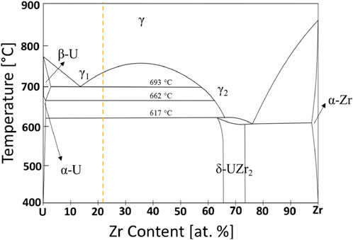
FIGURE 1. The U-Zr phase diagram [adapted from Salvato et al. (2022)]. The dashed orange line indicates the chemical composition of U-10Zr fuel (10 wt%, 22 at% Zr).
Reactor irradiation can significantly change the metallic fuel microstructure. U-10Zr fuel, for example, typically shows the formation of a concentric ring structure after reactor irradiation (Harp et al., 2017; Salvato et al., 2022). Each ring region has a unique combination of matrix phase, precipitates, fission gas bubbles, voids, and pores. The center region typically has round-shaped, relatively small pores, while the periphery region generally has large and irregular-shaped pores (Yao et al., 2020; Salvato et al., 2022; Yao et al., 2022). Identifying the matrix phase and precipitates is challenging due to the radioactivity and lack of suitable techniques. With the development of focus ion beam (FIB) site-specific sample preparation and scanning TEM (STEM)-based microstructural characterization, several reactor-irradiated U-10Zr fuel cross-section samples have been studied recently, focusing on the submicron and nano scale phase identification and chemical composition measurement (Yao et al., 2020; Benson et al., 2021; Liu et al., 2021; Salvato et al., 2022). The massive number of bubbles, voids, and pores, on the other hand, remains less explored due to the lack of suitable methods for SEM large dataset analyses.
In this study, we summarize our recent advanced characterization results, mainly worked out from the Irradiated Materials Characterization Laboratory (IMCL) of INL, on the as-cast annular U-10Zr fuel microstructure and post-irradiation examination (PIE) of the irradiated annular U-10Zr fuel cross-section. This is the first time samples of both fresh and irradiated specimens from the annular fuel have been characterized from bulk to nanometer and atomic scale. Reconstructions in 3D of fuel lamellae and rod-like phases, as well as Zr inclusions, were also obtained for the fresh fuel, strongly suggesting the fuel microstructure is not at equilibrium, and Zr inclusions are most likely being stabilized by O at high temperatures during casting. We also applied a computer vision-based machine learning (ML) model of pore detection on the large map of the entire irradiated fuel cross-section to provide quantitative insights into the irradiation-induced formation of microstructural pores. We used annular fuel development as a showcase for the great potential of multiscale materials characterization, coupled with ML artificial intelligence (AI) models, to support advanced fuel development.
2 Experiments
2.1 Fuel fabrication
Many methods were explored to fabricate annular fuels. Eventually, counter-gravity injection casting was identified as a viable method to produce operator-independent, full-length annular fuel (Listed, 2011). The annular U-10Zr fuel is clad with HT9, a martensitic ferritic steel, with a smear density of 55%. The fuel inner diameter was 3.25 mm, and the outer diameter was 4.86 mm.
2.2 In reactor irradiation
The irradiation experiments were conducted in the advanced test reactor (ATR) at INL (Hayes, 2006; Harp et al., 2018). During irradiation, the fuel rodlet was found to have poor cylindricity and formed a gap between the rodlet and capsule. The gap may have resulted in a variation of local cladding inner surface temperature from the values measured by thermal couples. Therefore, irradiation stopped at the end of 132 days with a peak burnup of 3.3% FIMA.
2.3 Sample preparation and SEM characterization
The as-cast fresh fuel pins were sectioned into several pieces. One piece was mounted in epoxy and polished using sandpaper and diamond suspensions with sequentially decreasing particle size from 15, 9, 3, to 1 µm. An SEM energy dispersive spectrum (EDS, Oxford ULTIM MAX SDD-EDS detector) was collected on a JEOL JSM-IT500 HR SEM at an accelerate voltage of 20 kV. The irradiated fuel pin was transferred from the ATR to the Hot Fuel Examination Facility (HFEF) for storage, sectioned into smaller samples, mounted, and metallurgically characterized before transferring to IMCL for advanced characterization.
2.4 FIB sample preparation and TEM characterization
TEM samples were prepared by the FIB technique (hereafter referred to as FIB-TEM sample) using an FEI Quanta 3D SEM/FIB dual beam system. Ga ion beams of various energy and currents were used during trenching and lift-out. Final thinning was done using 5 keV and 48 pA to locally perforate the sample, followed by a final polishing using a Ga ion beam of 2 keV and 27 pA. To avoid oxidation, the FIB-TEM sample was unloaded from FIB, surveyed, and quickly loaded into the FEI Titan Themis G2 200 scanning TEM (STEM) equipped with Super-X EDS system and high-angle annular dark field (HAADF) detectors. Bright-field image (BF), selected area diffraction patterns (SAED), and STEM-EDS were used to characterize the U-10Zr fuel microstructure at the nanometer scale.
2.5 Atom probe tomography (APT) analysis
The APT samples were prepared by conventional FIB milling using the same instrument for FIB-TEM sample preparation. The region of interest (near the FIB-TEM site) was covered with a ∼200 nm thick Pt deposit as a protective layer against milling damage. Trench cuts were made at a 22° stage tilt, then the APT lamella was lifted onto individual Si posts on a microtip array coupon. The mounted micro tips were FIB milled with different beam currents using an annular pattern having an inner diameter ranging from 2 μm to 100 nm. Low beam energies of 5 keV and 2 keV were used for the final milling stages to reduce Ga+ ion damage. APT samples were analyzed by a CAMECA local electrode atom probe (LEAP) 5000 at IMCL, and data were processed through Integrated Visualization and Analysis Software (IVAS version 3.8.4).
2.6 Decision tree modeling
The large image dataset for ML was collected using the FEI Helios G3 plasma FIB system at the IMCL. Images were collected at a 500× magnification in backscattered electron (BSE) scanning mode. A decision tree model developed in our previous work (Cai et al., 2022) was further trained and applied to reveal the pore size distribution and connectivity. The interpretable decision tree model was trained and validated on SEM images with fission gas pore boundaries depicted by experts. The model performance was evaluated to have a precision ratio >79–84% for pores with various size ranges and shapes.
3 Results and discussion
3.1 Fuel overview
Figure 2 is the microstructure image and SEM-EDS mapping of major elements, U and Zr, for the entire fuel cross section. Both elements have relatively uniform distribution throughout the fuel section. The empty space in the center was filled with a silicon-based epoxy during sample preparation. Surprisingly, the fuel inner and outer boundaries showed elevated concentrations of Zr: one followed the inner and the other followed the outer circle of the annular shape. The formation mechanism of the outer layer of the Zr-rich phase was attributed to the ZrO2 washer used during the casting process (Ryu et al., 2009; Capriotti and Harp, 2019). The inner Zr-rich band could be related to the chemical interaction between the fuel melt and the SiO2-based glass tube that was used to fill the center space so that cast fuel would form an annular shape once the glass tube was removed after casting.
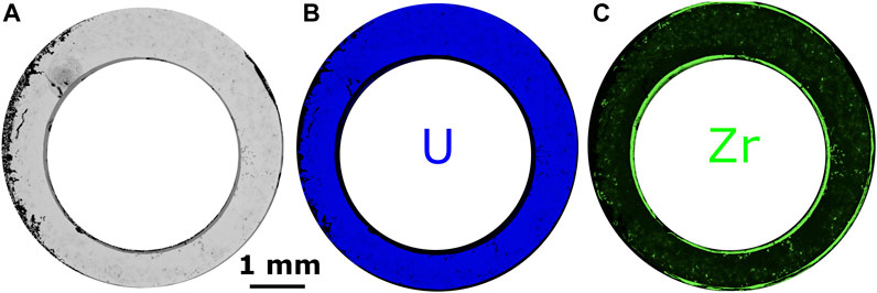
FIGURE 2. (A) Cross-section view of the annular fuel SEM; (B) EDS-U mapping; and (C) EDS-Zr mapping shows the cast fuel has a Zr-rich inner circle. Local regions inside the fuel matrix have Zr-rich globules and dendrites.
3.2 SEM bulk analysis
Figure 3 is the SEM analysis of the as-cast U-10Zr fuel microstructure. At low magnification, the microstructure is uniform except for the globular and dendritic Zr inclusion formed during the casting process. The Zr inclusion showed dark contrast in the SEM image. SEM-EDS quantification (Figures 3B,C) shows the overall concentration in the boxed region in Figure 3A is U-9.97Zr-0.23Si (in weight), close to the designed fuel alloy concentration of U-10Zr fuel. However, because SEM-EDS is a surface-sensitive technique, the weight percentage is only reported as a reference rather than a quantitative assessment.
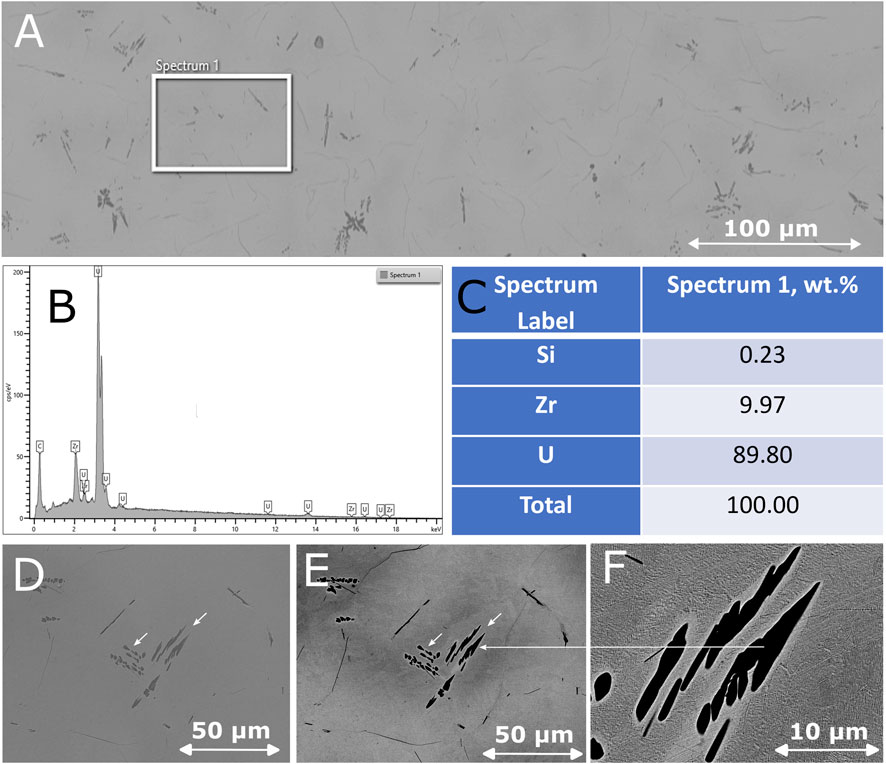
FIGURE 3. (A) SEM image of the as-cast U-10Zr microstructure showing a Zr inclusion in dark contrast; (B) SEM EDS spectrum; and (C) normalized chemical composition of the white boxed region show the overall chemical composition is close to the designed alloy value of 10% Zr. (D,E) Higher magnification SEM images show the large Zr inclusions in globular, dendritic, and needle shapes. The fuel matrix around the Zr inclusion (F) shows white contrast, suggesting a localized higher concentration of high-Z elements, possibly U.
The globular Zr inclusions were several microns in size, while the dendritic-shaped ones stretched to tens of microns in length. On the boundaries of the presumably high-temperature γ grains formed during casting, there were thin lines of a Zr-rich phase (Figures 3D–F). At higher magnification (Figure 4), the matrix microstructure showed a variation of contrast at the nanoscale following a lamella arrangement. The orientation of the lamella arrangement changed across the γ grain boundaries. Within gamma grain, the orientation also varied.
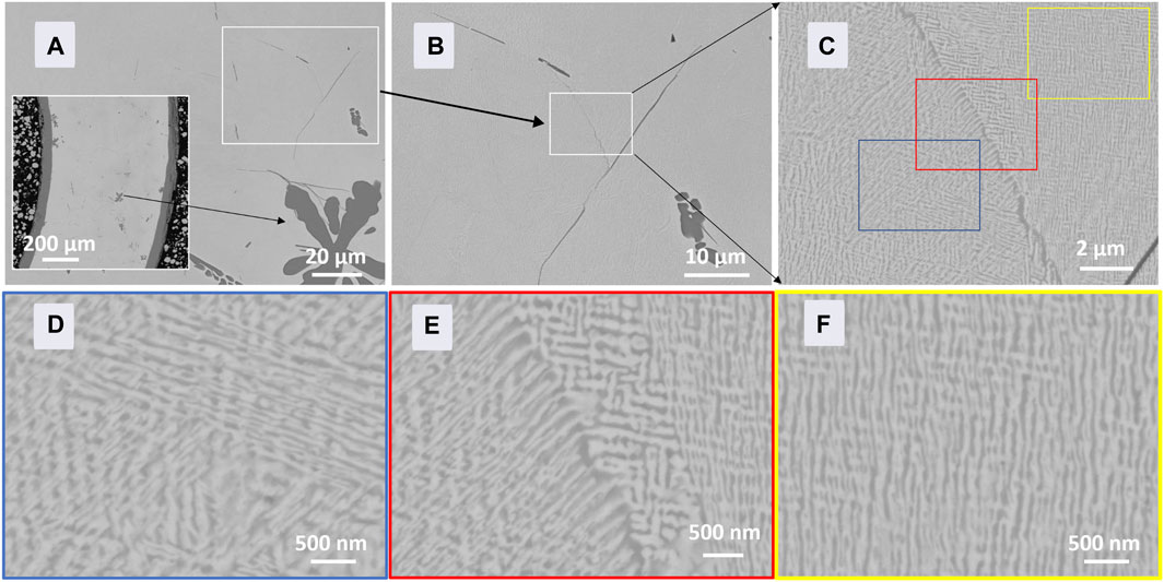
FIGURE 4. (A–C) SEM characterization of the nanoscale structure of as-cast U-10Zr fuel matrix; (D–F) are the close-ups of the different-colored boxed regions shown in (C).
3.3 TEM microstructural phase characterization
Because the lamella structure is at the nanoscale, we used TEM to characterize the microstructure, phase, and element distribution. TEM samples and APT samples were extracted from neighboring sites (Figures 5A,B) so that the two techniques could provide correlated results. The site shown in Figure 5C was chosen to capture the Zr globules (arrows indicated). The prepared TEM lift-out sample has a Zr globule in the upper right corner, as highlighted in Figure 5D.
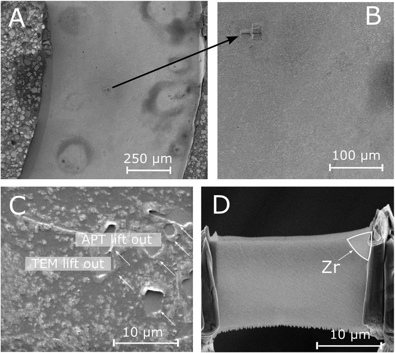
FIGURE 5. (A–B) Overview of the as-cast U-10Zr fuel shows the extraction site created by FIB sample preparation of TEM and APT (C); the (D) SEM image of the prepared TEM sample shows the Zr inclusion in the upper right corner.
STEM-EDS mapping of the region surrounding the Zr inclusion (Figure 6) illustrated the lamella microstructure of the U-10Zr fuel. TEM electron diffraction pattern indexing indicated the crystal structure of this inclusion was the same as α-Zr (Harris and Raynor, 1964) with a zone axis of [112
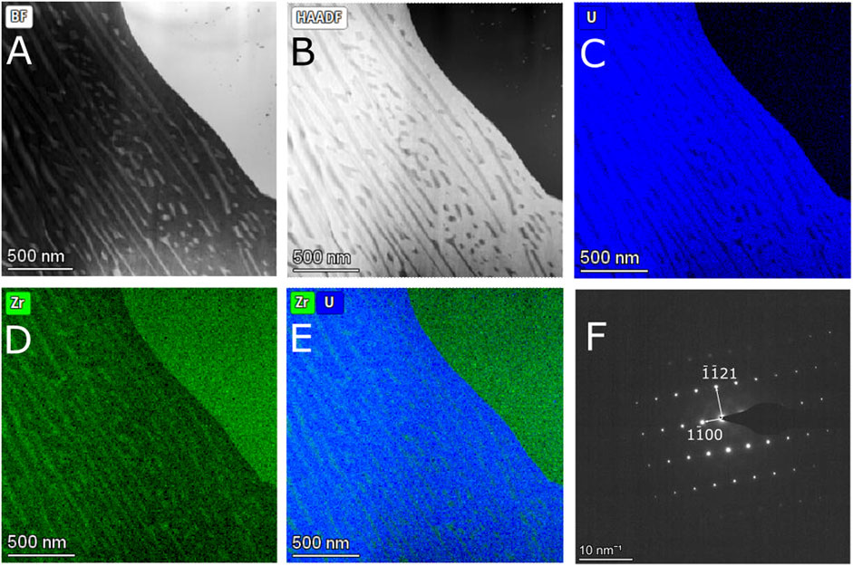
FIGURE 6. (A) STEM BF and (B) DF image of the fuel lamella structure with Zr inclusion as indicated by the chemical mapping of U and Zr (C–E). TEM SAED pattern indexing (F) shows the Zr inclusion has an α-Zr crystal structure viewed along the [112
STEM-EDS of another area of the sample revealed the fuel lamellae and rod-like fuel microstructure that had four different orientations (Figures 7A,B). SAED pattern collected from the red circled region in Figures 7C,D only showed a pattern indexable predominantly to α-U (Berndt, 1963) viewed close to the zone axis of [011]. A line scan of elements (Figures 7E–H) across the lamellae revealed the U-rich phase was nearly pure U, whereas the Zr-rich phase had a Zr/U ratio of around 1.22. This phase has long been thought of as the Uzr2 phase in literature (McKeown et al., 2013; Ahn et al., 2016; Irukuvarghula et al., 2016). The reason for the Zr deficiency may have been the thickness effect of the TEM samples. More specifically, the Zr-rich lamellae and rod-like features are smaller than the TEM foil thickness, which means that the matrix U phase covered the Zr phase throughout the TEM thickness along the electron beam transmission direction. Therefore, the Zr concentration was diluted by the U matrix phase.
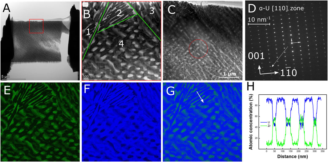
FIGURE 7. (A) Overview of the TEM sample with the boxed region shown in (B) at higher magnification, revealing the four numbered orientations of the lamellae structure. (C) is the TEM image of regions (red circle) where the SAED pattern (D) was collected from, indicating the phase is dominated by α-U. STEM EDS mappings (E–G) and the element distribution of U and Zr (H) along the path highlighted in (G).
3.4 APT 3D reconstruction
APT measurements provided a three-dimensional atomic scale reconstruction of a sharp, tip-shaped sample. ATP is a technique that combines time-of-flight mass spectrometry and ion projection microscopy. The atomic resolution makes APT an ideal tool for revealing the true chemical composition of nano lamellae and rod-like features free from the thickness effect of TEM samples. Because the APT samples are prepared at a site close to the TEM samples, the two techniques can provide complementary experimental data to improve our understanding of the U-10Zr fuel microstructure.
3.4.1 Lamella, rod-like, and fuel matrix phase
APT is a suitable method for revealing the true chemical composition of the lamellae and the rod-like and fuel matrix phases. The tip prepared by a site-specific FIB technique successfully captured the lamellae interfaces. Results of atomic concentration quantification showed the lamella or rod-like Uzr2 phase roughly followed the stoichiometric composition line (Figure 8E, green dash). Close to the interface, the U and Zr concentrations vary slightly from the stoichiometric values, possibly due to the metastable nature of the as-cast microstructure.
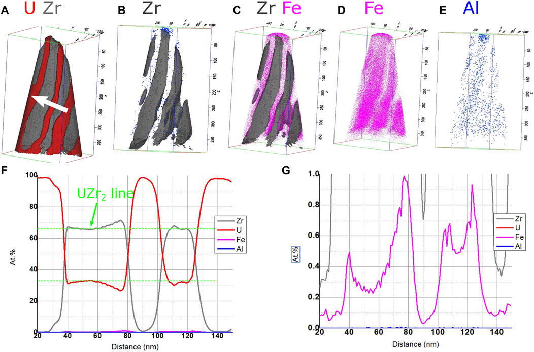
FIGURE 8. (A–E) APT 3D reconstruction of U, Zr, Fe, and Al across the fuel matrix and lamella phase. (F) The interface between U and Zr-rich lamellae shows a gradual change of concentration. (G) Fe impurities are mainly from the Zr feedstock. Inside the U fuel matrix phase, the Fe impurity level is around 0.05%.
Fe and Al impurities were also revealed by APT analysis. These impurities were most likely introduced to the materials system by alloying Zr because both impurities overlap with the lamellae and rod-like phases. The Zr concentration in the pure U matrix phase is close to 0.4 at%, which roughly agrees with the 0.5% Zr solubility limit in the α-U phase at 662°C (Sheldon and Peterson, 1989).
3.4.2 Global/dendritic Zr inclusion
The formation mechanism of Zr inclusions in U-10Zr fuel remains elusive. Based on the U-Zr phase diagram, with a U-10Zr composition, the microstructure should only contain the ⍺-U and UZr2 phases at room temperature (Figure 1). However, large Zr inclusions, as shown in Figure 3A, have been observed in numerous locations. In this study, through a combination of SEM-EDS, STEM-EDS, and TEM-SAED techniques, we confirmed that the Zr inclusions adopt a hexagonal crystal structure, the same as α-Zr. However, the above-mentioned EDS technique could not reliably determine the concentration of light elements, such as O, N and C.
APT has been widely and reliably used to measure O concentration to 10 s ppm in Ni (Poplawsky et al., 2022) and Zr alloys (de Gabory et al., 2015). Oxygen up to 30 at% can dissolve into α-Zr and form α-Zr (O) during either autoclave corroding in 360°C water conditions (de Gabory et al., 2015) or high-temperature oxidation up to 600 K (Tanabe and Tomita, 1989).
The 3D reconstruction of the prepared tip (Figure 9) covers the three major phases in the as-cast U-10Zr fuel. Following the white arrow, from left to right, they are UZr2, α-U, and Zr inclusion. O, N, and C concentrations have been plotted for discussion. An appreciable amount of oxygen up to 17.5 at% is found in the Zr inclusion, whereas the carbon and nitrogen concentrations are negligible.
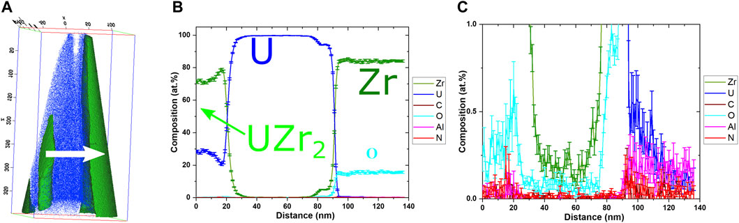
FIGURE 9. (A) APT 3D reconstruction of U and Zr in the region close to a Zr inclusion. (B) The U-rich region right before the Zr inclusion is wider than a typical U lamella; ∼17.5 at% O is detected in the inclusion. (C) The concentration of other light elements, such as C and N, is close to background values.
Historically, the Zr inclusion has been categorized as a phase stabilized by oxygen or nitrogen (Janney and O’Holleran, 2015). Our data indicate the α-Zr is possibly stabilized by oxygen. In future fuel casting work, careful control of oxygen in the fabrication environment may benefit Zr inclusion population control.
APT data also showed that, with the formation of large Zr inclusions, the nearby Zr concentration dropped to 0.2 at%, which is half the solubility limit for Zr in an ⍺-U matrix (Figure 8). The lower Zr concentration suggested the Zr inclusions grow at the sacrifice of Zr in the nearby U matrix. This matched with the white band that surrounded the large Zr inclusions shown (Figure 3F).
3.5 ATR irradiation and post-irradiation examination
Fuel assembly was carried out in the Materials & Fuels Complex (MFC) at INL. The fuel pin was sealed into HT-9 cladding and backfilled with helium gas. The assembled fuel cladding rodlet was sealed into another cylindrical container that served as the primary safety boundary between the fuel and the ATR coolant. For detailed information about the capsule design and irradiation conditions, please refer to our previous publication (Harp et al., 2018).
During irradiation of the solid metallic fuel, a temperature gradient of 200°C between the relatively hot fuel center and the cold cladding inner surface is typically observed. The annular fuel, with empty space in the center, created a different temperature distribution. Detailed finite element-based modeling of the temperature distribution can be found in Medvedev (2016).
After irradiation, the fuel center empty space was filled by irradiation-induced swelling of fuel materials (Figure 10). Because there was still enough empty space in the center to accommodate fuel swelling, the strain and force applied on the fuel from cladding were estimated to be minimal. For this reason, we used “swelling” instead of “creep” to describe the filling of the center empty space by fuel materials.
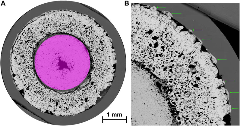
FIGURE 10. (A) SEM image of irradiated annular fuel (3.3% FIMA burnup) shows the formation of the center region and increased porosity in the annular fuel region after irradiation; (B) localized fuel cladding chemical interaction regions inside cladding as highlighted by the green arrows.
The center region (pink) was less porous than the annular region (Figure 10A). The image contrast also differs between the two regions, suggesting a different phase nature. A previous study resolved the center region as a BCC UZr2 phase with nano omega domains, while the annular region was found to be α-U with nano Zr clusters (Yao et al., 2020).
Figure 10B revealed the localized and sizable fuel cladding chemical interactions (FCCI) that formed a band feature (green arrowed) inside the cladding. Our previous study (Liu et al., 2021) identified the formation of various intermetallic compounds, such as the Fe-Cr sigma phase, Fe-Cr-U-Si compounds, Cr-rich bands, and uranium carbides, in the FCCI regions. Surprisingly, lanthanide fission products were not detected in this region.
Because FCCI is a solid-state chemical reaction between fuel and cladding components, the local inner cladding temperature is one of the principal parameters that control FCCI (Wang et al., 2022).
The estimated peak inner cladding temperature was around 540°C, generally falling into the range of EBR-Ⅱ and FFTF values and suggesting the fuel would be well behaved during irradiation. Based on PIE observation and PIE-informed finite element-based modeling that takes the discrete contact between fuel and cladding into consideration, it was found that the local cladding temperature could be as high as 597°C (Medvedev, 2016). The large voids (Figure 10B) could further increase the fuel temperature from 597°C to 739°C (Medvedev, 2016), which is much higher than the EBR-Ⅱ and FFTF cladding temperatures.
3.6 Lanthanide migration
EBR-Ⅱ fuel studies showed that lanthanide fission products rapidly migrate from the fuel center to the fuel cold peripheral surface. Above 500°C, lanthanide fission products, such as La, Ce, Pr, and Nd, have similar high solubility in molten cesium (Cs) and sodium (Na) (Mariani et al., 2011). Cs is a fission product with a low melting point of 28°C. Na is the thermal bond between the fuel and the cladding with a melting point of 98°C. At reactor operating conditions, when irradiation-induced pores grow to a large size and become connected, liquid Cs and Na will permeate through the connected pores into the fuel. Lanthanide FPs will dissolve into the liquid Cs and Na and migrate through the connected pores in the fuel from the hot center to the cold periphery and precipitate out due to the temperature drop.
One of the primary goals of annular fuels is to eliminate the Na thermal bond to remove the pyrophoric concerns during fuel reprocessing at the back end of the fuel cycle. Whether the elimination of Na impacts the liquid-like transport mechanism of lanthanides during normal reactor operation conditions remains an open question. Without Na, the amount of available Cs to act as a lanthanide solvent is only 0.65 g in 100 g of irradiated U-10Zr fuel to 8% burnup (Mariani et al., 2011).
After irradiation, phase identification showed the matrix phase in the center region was the UZr2 phase in the BCC crystal structure with nano omega domains. Between the center and the annular region, there is zigzag rich in Zr and Si (Figures 11D, E). Most of the lanthanide fission products, represented by Nd mapping, remained in the center Zr-rich region. An increase of Nd concentration towards the zigzag interface suggested the movement of lanthanides followed the temperature gradient even in the absence of liquid Na.
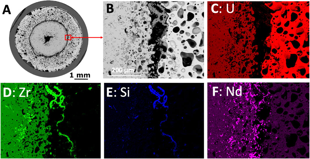
FIGURE 11. (A) Irradiated fuel cross section and (B) interface region between Zr rich fuel center and U rich annular region and corresponding (C-F) SEM-EDS element mapping.
To reveal the solid–solid interaction between the lanthanide fission products and the UZr2 fuel matrix, a FIB-TEM sample was prepared directly on the interface between a lanthanide particle and the UZr2 fuel matrix (Figure 12). The region of interest was inside the center region but close to the zigzag interface. The lanthanide FPs are round particles of darker contrast than the UZr2 fuel matrix shown in Figure 12A. The white semi-transparent box marks the location of the FIB-TEM lift-out sample, as shown in Figure 12B.
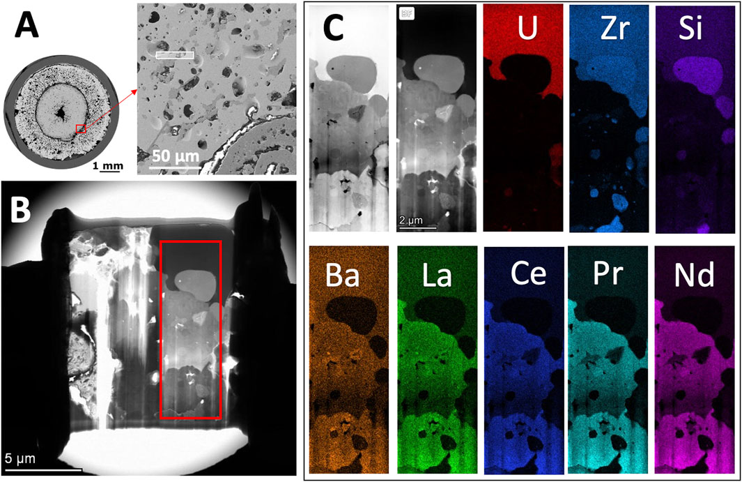
FIGURE 12. (A) SEM image of the location of the FIB-TEM sample (semi-transparent box) relative to the entire fuel cross section; (B) STEM BF image of the FIB-TEM sample captured the boundary between the lanthanide and the fuel center UZr2 phase; (C) STEM images and EDS element mappings show the lanthanide particle has many nanocrystalline grains rich in La, Ce, Pr, and Nd as well as Ba.
STEM-EDS maps (Figure 12C) show the lanthanide particle contained multiple nanocrystallites. Inside the lanthanide particle, there were regions rich in La but poor in Ce, Pr, and Nd, suggesting La can have a different distribution pattern. The periphery of the lanthanide particle was surrounded by ZrSix particles and restrained by the UZr2 phase.
The lanthanide particles were located inside a pore. Although we cannot confirm that without Na, the liquid Cs assisted the transport of lanthanide fission products based on current experimental evidence, the movement of lanthanide FPs is closely related to the pores. The next section will provide the statistical analysis of the pores using ML models.
3.7 Materials informatics on pores
This section describes the use of computer vision-based ML models to better understand the pores in a quantitative manner.
We applied the decision tree model developed in our recent publication (Cai et al., 2022) on the map of the fuel cross section stitched from SEM images. The model was trained and validated on pores with boundaries manually outlined by experts. The model takes the pore size, shape, and connectivity into consideration. It can also classify the pores into different types based on the detected deposition on their inside surfaces. The goal was to provide pixel-level pore classification and segmentation to reveal the difference in the pore size and types between the center zone (Figure 13A) and the annular zone (Figure 13B).
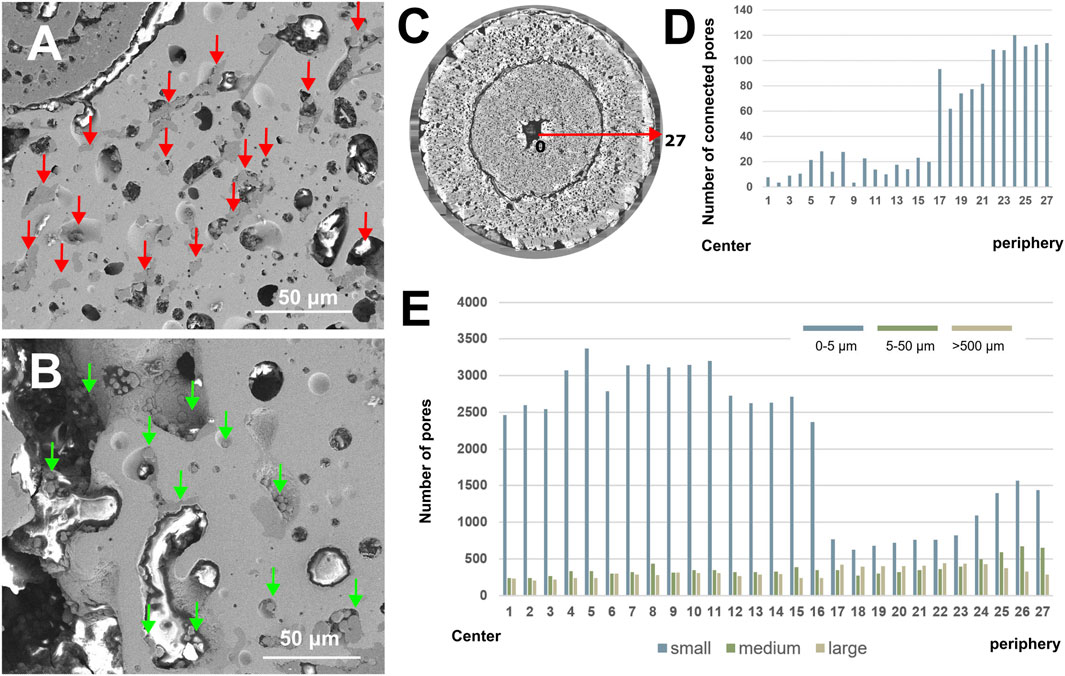
FIGURE 13. (A) Solid fission products in the center region located near or inside the pores (red arrow) are relatively isolated from each other. (B) Solid fission products in the annular region clustered inside the interconnected pores (green arrow). (C–E) Application of the decision tree machine learning model revealed the pore statistics from the fuel center to the outmost annular region. The data are from ∼50,000 pores.
The pores in the center region were generally small and isolated from each other. The lanthanide fission products were still located inside the pores. The pores in the annular region were typically larger and connected. Inside the large connected pores, the lanthanide fission products showed a sludge-like morphology like that observed near the FCCI region in EBR-Ⅱ fuel (Mariani et al., 2011). However, the particles appeared to have no preference for the cold or warm side of the pore surface.
A clear boundary is visible in Figures 13C–E, matching the location of the zigzag interface. The results, combined with Figure 11, indicate that the lanthanide can migrate through the relatively dense solid UZr2 phase in the center region, even though most pores were small and isolated. Later, the lanthanide FPs accumulated around the zigzag interface between the center and annular region. The reason for this accumulation remains unclear at this time.
4 Conclusion
This article highlighted the capability of INL facilities to support the development of advanced metallic fuels for future fast-spectrum reactors. Inside the INL complexes, the metallic fuel samples can be cast, pre-irradiation characterized, assembled into rodlets in MFC, and then transferred to ATR for neutron irradiation. After irradiation, irradiated fuel assemblies can be transferred to HFEF for sample handling and sectioning. Down-sized samples with lower radioactivity can be transferred to IMCL in a timely manner for advanced PIE and fuel performance assessment.
This article is also the first corelative FIB-TEM-APT study to characterize the nanoscale-modulated U-10Zr fuel as-cast microstructure at different length scales. APT revealed a strong correlation between high oxygen concentration and the Zr-rich globules and dendrites. Newly developed ML models also enabled a timely advanced data analysis to quantitatively reveal the fission gas pore density and size distribution over the entire fuel cross section. Such capability could profoundly change the outcome of PIE to foster a deep understanding of fuel microstructure and property evolution during irradiation to support fuel development, demonstration, and qualification for advanced reactors.
Data availability statement
The raw data supporting the conclusion of this article will be made available by the authors, without undue reservation.
Author contributions
TY: experimental design, idea development, article writing, and funding; MB: APT; FD: SEM-EDS; FX: machine learning; FT: FIB; DM: FIB; MTB: idea development; LC: idea development and funding. All authors contributed to the article and approved the submitted version.
Funding
This work was supported by the U.S. Department of Energy, Office of Nuclear Energy under DOE Idaho Operations Office Contract DE-AC07-05ID14517. Funding for fuel fabrication and irradiation experiments and baseline PIE was provided by the Advanced Fuel Campaign. Advanced characterization was supported through Thermal Energy Transportation under Irradiation (TETI) EFRC. The machine learning and artificial intelligence model development and application were supported by INL Laboratory Directed Research and Development (LDRD 22A1059-094FP).
Acknowledgments
This manuscript has been authored by Battelle Energy Alliance, LLC, under contract No. DE-AC07–05ID14517 with the U.S. Department of Energy. The publisher, by accepting the article for publication, acknowledges that the U.S. Government retains a nonexclusive, paid-up, irrevocable, worldwide license to publish or reproduce the published form of this manuscript, or allow others to do so, for U.S. Government purposes. This article is impossible without the prior efforts of multiple personnel from the Idaho National Laboratory. Our great appreciation goes to Tom O’Holleran, Leah Squires, Rendy Fielding, Tim Hyde, Rory Kennedy, Jian Gan, and Lingfeng He, who helped to facilitate this study at different stages. We also acknowledge the great help from operation team members, including but not limited to, Jayson Bush, Miles Cook, and John Howard from IMCL.
Conflict of interest
The authors declare that the research was conducted in the absence of any commercial or financial relationships that could be construed as a potential conflict of interest.
Publisher’s note
All claims expressed in this article are solely those of the authors and do not necessarily represent those of their affiliated organizations, or those of the publisher, the editors and the reviewers. Any product that may be evaluated in this article, or claim that may be made by its manufacturer, is not guaranteed or endorsed by the publisher.
References
Ahn, S., Irukuvarghula, S., and McDeavitt, S. M. (2016). Microstructure of α-U and δ-UZr2 phase uranium–zirconium alloys irradiated with 140-keV He+ ion-beam. J. Alloys Compd. 681, 6–11. doi:10.1016/j.jallcom.2016.04.219
Benson, M. T., Harp, J. M., Xie, Y., Yao, T. K., Tolman, K. R., Wright, K. E., et al. (2021). Out-of-pile and postirradiated examination of lanthanide and lanthanide-palladium interactions for metallic fuel. J. Nucl. Mater. 544, 152727. doi:10.1016/j.jnucmat.2020.152727
Benson, M. T., King, J. A., Mariani, R. D., and Marshall, M. C. (2017). SEM characterization of two advanced fuel alloys: U-10Zr-4.3Sn and U-10Zr-4.3Sn-4.7Ln. J. Nucl. Mater. 494, 334–341. doi:10.1016/j.jnucmat.2017.07.057
Berndt, A. (1963). Room temperature lattice constants of alloys of plutonium in alpha-uranium. J. Nucl. Mater. 9 (1), 53–58. doi:10.1016/0022-3115(63)90167-3
Cai, L., Xu, F., Di Lemma, F. G., Giglio, J. J., Benson, M. T., Murray, D. J., et al. (2022). Understanding fission gas bubble distribution, lanthanide transportation, and thermal conductivity degradation in neutron-irradiated α-U using machine learning. Mater. Charact. 184, 111657. doi:10.1016/j.matchar.2021.111657
Capriotti, L., and Harp, J. (2019). Status PIE report on legacy EBR-II and FFTF metallic fuel experiments, Idaho national lab INL. Idaho Falls, ID (United States): Idaho National Lab.INL.
Crawford, D. C., Porter, D. L., and Hayes, S. L. (2007). Fuels for sodium-cooled fast reactors: US perspective. J. Nucl. Mater. 371 (1), 202–231. doi:10.1016/j.jnucmat.2007.05.010
de Gabory, B., Dong, Y., Motta, A. T., and Marquis, E. A. (2015). EELS and atom probe tomography study of the evolution of the metal/oxide interface during zirconium alloy oxidation. J. Nucl. Mater. 462, 304–309. doi:10.1016/j.jnucmat.2015.03.043
Fielding, R. S., Crapps, J., Unal, C., and Kennedy, J. (2013). Metallic fuel casting development and parameter optimization simulations. Idaho Falls, ID (United States): Idaho National Lab.INL.
Harp, J. M., Chichester, H. J. M., and Capriotti, L. (2018). Postirradiation examination results of several metallic fuel alloys and forms from low burnup AFC irradiations. J. Nucl. Mater. 509, 377–391. doi:10.1016/j.jnucmat.2018.07.003
Harp, J. M., Porter, D. L., Miller, B. D., Trowbridge, T. L., and Carmack, W. J. (2017). Scanning electron microscopy examination of a Fast Flux Test Facility irradiated U-10Zr fuel cross section clad with HT-9. J. Nucl. Mater. 494, 227–239. doi:10.1016/j.jnucmat.2017.07.040
Harris, I., and Raynor, G. (1964). The electronic state of cerium in zirconium-cerium alloys. J. Less Common Metals 6 (1), 70–80. doi:10.1016/0022-5088(64)90008-6
Hayes, S. L. (2006). Irradiation of metallic fuels with rare earth additions for actinide transmutation in the advanced test reacto experiment description for AFC-2A and AFC-2B, Idaho national lab (INL). Idaho Falls, ID (United States): Idaho National Lab.INL.
Irukuvarghula, S., Ahn, S., and McDeavitt, S. M. (2016). Decomposition of the γ phase in as-cast and quenched U–Zr alloys. J. Nucl. Mater. 473, 206–217. doi:10.1016/j.jnucmat.2016.02.028
Janney, D. E., and O’Holleran, T. P. (2015). Zr inclusions in actinide–Zr alloys: New data and ideas about how they form. J. Nucl. Mater. 460, 13–15. doi:10.1016/j.jnucmat.2015.01.065
Krall, L., and Macfarlane, A. (2018). Burning waste or playing with fire? Waste management considerations for non-traditional reactors. Bull. Atomic Sci. 74 (5), 326–334. doi:10.1080/00963402.2018.1507791
Li, S. X., Sofu, T., Johnson, T. A., Wigeland, R. A., and Laug, D. V. (2000). Experimental observations on electrorefining spent nuclear fuel in molten LiCl-KCl/liquid cadmium system. J. New Mater. Electrochem. Syst. 3 (3), 259–268.
Listed, N. (2011). Advanced fuels campaign FY 2011 accomplishments report. Idaho Falls, ID (United States): Idaho National Lab.INL.
Liu, X., Capriotti, L., Yao, T., Harp, J. M., Benson, M. T., Wang, Y., et al. (2021). Fuel-cladding chemical interaction of a prototype annular U-10Zr fuel with Fe-12Cr ferritic/martensitic HT-9 cladding. J. Nucl. Mater. 544, 152588. doi:10.1016/j.jnucmat.2020.152588
Mariani, R. D., Porter, D. L., O’Holleran, T. P., Hayes, S. L., and Kennedy, J. R. (2011). Lanthanides in metallic nuclear fuels: Their behavior and methods for their control. J. Nucl. Mater. 419 (1), 263–271. doi:10.1016/j.jnucmat.2011.08.036
McKeown, J. T., Irukuvarghula, S., Ahn, S., Wall, M. A., Hsiung, L. L., McDeavitt, S., et al. (2013). Coexistence of the α and δ phases in an as-cast uranium-rich U–Zr alloy. J. Nucl. Mater. 436 (1), 100–104. doi:10.1016/j.jnucmat.2013.01.313
Medvedev, P. G. (2016). BISON investigation of the effect of the fuel-cladding contact irregularities on the peak cladding temperature and FCCI observed in AFC-3A rodlet 4, Idaho national lab (INL). Idaho Falls, ID (United States): Idaho National Lab.INL.
Miao, Y., Stauff, N., Oaks, A., Yacout, A. M., and Kim, T. K. (2019). Fuel performance evaluation of annular metallic fuels for an advanced fast reactor concept. Nucl. Eng. Des. 352, 110157. doi:10.1016/j.nucengdes.2019.110157
Park, J., Cho, S. Y., Youn, Y. S., Lee, J., Kim, J. Y., Park, S. H., et al. (2019). Anisotropic lattice thermal expansion of uranium-based metallic fuels: A high-temperature X-ray diffraction study. J. Nucl. Mater. 527, 151803. doi:10.1016/j.jnucmat.2019.151803
Planchon, H. P., Singer, R. M., Mohr, D., Feldman, E. E., Chang, L. K., and Betten, P. R. (1986). The experimental breeder reactor II inherent shutdown and heat removal tests — Results and analysis. Nucl. Eng. Des. 91 (3), 287–296. doi:10.1016/0029-5493(86)90082-8
Poplawsky, J. D., Pillai, R., Ren, Q. Q., Breen, A. J., Gault, B., and Brady, M. P. (2022). Measuring oxygen solubility in Ni grains and boundaries after oxidation using atom probe tomography. Scr. Mater. 210, 114411. doi:10.1016/j.scriptamat.2021.114411
Ryu, H. J., Oh, S. J., Lee, C. T., Ko, Y. M., Woo, Y. M., and Lee, C. B. (2009). Effects of rare earth elements on the surface interaction of U-Zr-Ce metallic fuel. Gyeongju, Korea: Transactions of the Korean Nuclear Society Autumn Meeting.
Salvato, D., Liu, X., Murray, D. J., Paaren, K. M., Xu, F., Pavlov, T., et al. (2022). Transmission electron microscopy study of a high burnup U-10Zr metallic fuel. J. Nucl. Mater. 570, 153963. doi:10.1016/j.jnucmat.2022.153963
Sheldon, R. I., and Peterson, D. E. (1989). The U-Zr (Uranium-Zirconium) system. Bull. Alloy Phase Diagrams 10 (2), 165–171. doi:10.1007/bf02881432
Sofu, T. (2011). “SODIUM-COOLED fast reactor (sfr) safety,” in International seminar on nuclear war and planetary emergencies—43rd session. (Erice, Italy: World Scientific), 123–129.
Tanabe, T., Tanaka, M., and Imoto, S. (1987). AES and XPS studies of oxygen stabilized alpha zirconium. Surf. Sci. 187 (2), A330–A331. doi:10.1016/0167-2584(87)90935-2
Tanabe, T., and Tomita, M. (1989). Surface oxidation of zirconium above room temperature. Surf. Sci. 222 (1), A542–A594. doi:10.1016/0167-2584(89)90193-x
Wang, Y., Frazer, D. M., Cappia, F., Teng, F., Murray, D. J., Yao, T., et al. (2022). Small-scale mechanical testing and characterization of fuel cladding chemical interaction between HT9 cladding and advanced U-based metallic fuel alloy. J. Nucl. Mater. 566, 153754. doi:10.1016/j.jnucmat.2022.153754
Yacout, A. M. (2008). Long-Life metallic fuel for the super safe, small and simple (4S) reactor. United States: Nuclear Regulatory Commission.
Yao, T., Capriotti, L., Harp, J. M., Liu, X., Wang, Y., Teng, F., et al. (2020). α-U and ω-UZr2 in neutron irradiated U-10Zr annular metallic fuel. J. Nucl. Mater. 542, 152536. doi:10.1016/j.jnucmat.2020.152536
Keywords: high burnup fuel, metallic fuel, cast, irradiation, post-irradiation examination, materials informatics
Citation: Yao T, Bachhav M, Di Lemma FG, Xu F, Teng F, Murray DJ, Benson MT and Capriotti L (2023) The advanced characterization, post-irradiation examination, and materials informatics for the development of ultra high-burnup annular U-10Zr metallic fuel. Front. Nucl. Eng. 1:1050262. doi: 10.3389/fnuen.2022.1050262
Received: 21 September 2022; Accepted: 09 November 2022;
Published: 19 June 2023.
Edited by:
Karl Whittle, University of Liverpool, United KingdomReviewed by:
Tianyi Chen, Oregon State University, United StatesKathryn Margaret Peruski, Oak Ridge National Laboratory (DOE), United States
Copyright © 2023 Yao, Bachhav, Di Lemma, Xu, Teng, Murray, Benson and Capriotti. This is an open-access article distributed under the terms of the Creative Commons Attribution License (CC BY). The use, distribution or reproduction in other forums is permitted, provided the original author(s) and the copyright owner(s) are credited and that the original publication in this journal is cited, in accordance with accepted academic practice. No use, distribution or reproduction is permitted which does not comply with these terms.
*Correspondence: Tiankai Yao, dGlhbmthaS55YW9AaW5sLmdvdg==