 Devanshi Bhardwaj1
 Bin Cheng1
 David J. Sprouster1William S. Cunningham1
 Nirmala Rani1
 Jason R. Trelewicz1,2
 Lance L. Snead1*
- 1Department of Materials Science and Chemical Engineering, Stony Brook University, Stony Brook, NY, United States
- 2Institute for Advanced Computational Science, Stony Brook University, Stony Brook, NY, United States
With significant improvement in High Temperature Superconductors (HTS), several projects are adopting HTS technology for fusion power systems. Compact HTS tokamaks offer potential advantages including lower plant costs, enhanced plasma control, and ultimately lower cost of electricity. However, as compact reactors have a reduced radial build to accommodate shielding, HTS degradation due to radiation damage or heating is a significant and potentially design limiting issue. Shielding must mitigate threats to the superconducting coils: neutron cascade damage, heat deposition and potentially organic insulator damage due x-rays. Unfortunately, there are currently no hi-performance shielding materials to enable the potential performance enhancement offered by HTS. In this work, we present a manufacturing method to fabricate a new class of composite shields that are high performance, high operating temperature, and simultaneously neutron absorbing and neutron moderating. The composite design consists of an entrained metal-hydride phase within a radiation stable MgO ceramic host matrix. We discuss the fabrication, characterization, and thermophysical performance data for a series of down-selected composite materials inspired by future fusion core designs and their operational performance metrics. To our knowledge these materials represent the first ceramic composite shield materials containing significant metal hydrides.
1 Introduction
With the significant technological improvements in High Temperature Superconductors (HTS) a few commercial and national-led programs are moving towards fusion power systems based on high-field HTS technology (Sorbom et al., 2015; Gryaznevich and Asunta, 2017; Kuang et al., 2018). Compact HTS tokamaks offer several potential technical and economic advantages as compared to the larger conventional superconducting tokamaks including lower plant cost, enhanced plasma control, and ultimately lower cost of electricity (Sorbom et al., 2015; Creely et al., 2020). However, while the HTS tape irradiation performance has yet to be established, it is unlikely that its neutron damage tolerance will be far superior to the conventional Nb3Sn or NbTi low-temperature superconductors. Moreover, as compact fusion systems unavoidably have reduced structure available to shield the HTS from neutron and gamma irradiation (i.e., less combined radiation stopping power associated with the first wall, blanket, vacuum vessel, thermal gap and neutron shield) though have similar or greater neutron wall loading (especially inboard) as compared to more conventional tokamak designs, HTS irradiation-induced degradation is a significant and potentially design limiting issue.
Typically, the neutron wall loading of compact fusion systems can be significantly higher than, as example, the European DEMO system (Federici et al., 2018) or similar “ITER scale” tokamaks. The impact of these physical contraints can be visualized by inspection Figure 1, which provide cutaway views of the International Thermonuclear Experimental Reactor (ITER) and a conceptualized HTS spherical torus, each with a scale worker demonstrating compact nature of the HTS machine. This point is reinfored when considering the total transit distance available for radiation scattering or absorbtion inboard (e.g., the radial build of First Wall+Blanket+Vacuum Vessel+Thermal Gap) for ITER is 72.5 cm as compared to ∼24 cm and ∼23 cm for the Commonwealth Fusion Systems ARC and Tokamak Energy designs, respectively. While the compact HTS designs do provide slightly more space in the shield gap (approximately 60 cm as compared to 45.5 cm for ITER), the loss of overall inboard structure along with the approximately factor of two higher neutron wall loading poses a signficant irradiation damage challenge to magnet and shield designers.
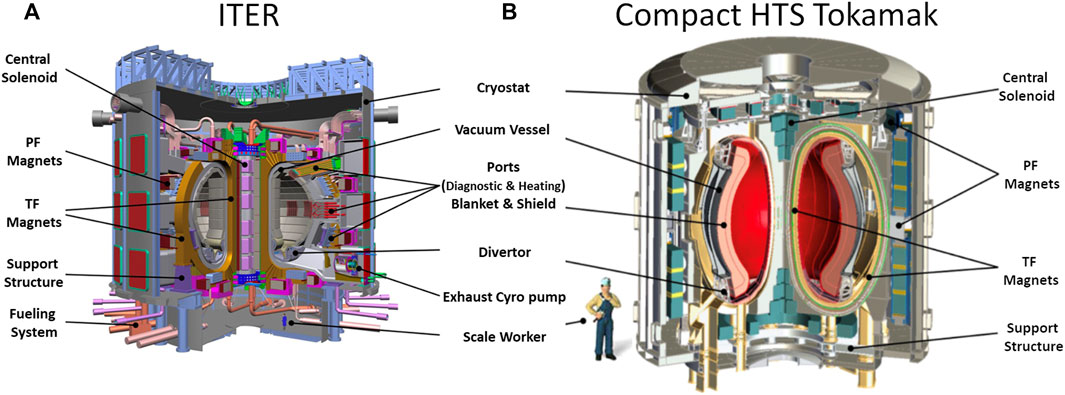
FIGURE 1. Tokamak Scale Comparison: Cross section of ITER (A) adapted from ITER organization with a concept diagram (B) of Tokamak Energy’s spherical torus utilizing high-field HTS.
The potential for HTS technology to enable economics and performance of fusion reactors largely depends on the ability to engineer robust compact systems. A number of common materials have been utilized as neutron and gamma shields, though some are unsuitable for use in power plant applications. For example, while the combination of borated steel and water (e.g., Type 304B7 steel for ITER) or the alternating WC-WB2/water plates suggested in advanced spherical torus design (CG and JG, 2017) simultaneously address neutron and gamma slowing and capture, the neutronic burnout of B10 (Windsor, et al., 2018) is a concern and the impact on plant thermal efficiency of water-cooling argues against its use. Moreover the relatively short-lived (7.1 s) half-life isotopes in water (i.e. 16O->16N) raise safety concerns (Taylor et al., 2017). One approach to achieving the similar neutron moderation effectiveness provided by water is to utilize relatively small segmented or “massive” metal hydrides, whose atomic hydrogen densities approach or slightly exceed that of water. However, the very real safety hazard associated with thermal and irradiation-induced dissociation of hydrogen disqualifies monolithic hydrides from consideration. A potential solution to this issue of uncontrolled hydrogen loss was recently demonstrated by our team (Snead et al., 2019) whereby metal hydrides were entrained within a thermally stable matrix of low-hydrogen-diffusing ceramic. In that application the composite was engineered for fission reactor moderation, maximizing the content of ZrH2 to moderate neutrons with very little capture. While fabricating such a composite (as compared to a monolithic hydride) certainly reduces the average hydrogen density the presence of the composite matrix can serve to retain hydrogen. Broader considerations for such a composite shield concept are presented in Figure 2: as the threat to the HTS magnet is both from electromagnetic radiation (x-ray) and fast neutrons, the matrix and entrained phase composition should be optimized to address these issues while considering long-term irradiation and thermal performance. Conceptually, the shield material will have modest load requirements such that the composite matrix provides a primary but modest structural function and a secondary shielding function (if possible, to slow neutrons or potentially scatter gamma rays.) Additionally, neutron-induced activation and stability are considerations for the shield composite matrix. Most importantly, when considering a metal hydride entrained phase, beyond basic processing and long-term thermal compatibility, the matrix should mitigate loss of hydrogen through diffusional transport.
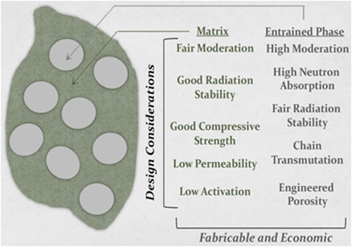
FIGURE 2. Conceptual schematic of a two-phase engineered composite shield material.
The ability to access a shield composite processing window while avoiding high hydrogen loss from the entrained metal hydride is central to this concept. As the list of nuclear-grade ceramics considered stable for shield application in a neutron environment (SiC, Al2O3, MgAl2O3, MgO … ) all have nominal sintering temperatures well more than 1,000°C, co-sintering with metal hydrides is a challenge or simply impractical. This can be seen from inspection of Figure 3, which provides a plateau pressure for a range of hydrides, including a number of highly absorbing metal hydrides (MHx: M = Gd, Eu, Hf … )
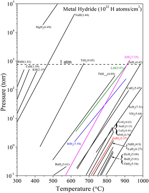
FIGURE 3. Plateau pressure of select hydrides, including ZrH2 utilized in previous work for MgO: ZrH2 moderators (9–13) and highly neutron absorbing metal hydrides used in this study MgO: HfH2. Figure adapted from Vetrano (1971).
In our previous work (Cheng et al., 2022; Snead et al., 2022; Snead et al., 2023; Snead and Trelewicz, 2023), composite sintering temperature was significantly suppressed through the use of LiF sintering aid in the monolithic MgO and MgO (LiF): ZrH2 systems. This initial 350°C reduction in MgO sintering temperature, and the 250°C increased processing temperature for ZrH2 through processing in a hydrogen atmosphere allowed the first demonstration of a ceramic-matrix metal-hydride composite. In that case the entrained metal hydride was loaded to a metal hydride fraction up to and exceeding 50% by volume. While ZrH2 is an excellent neutron moderator, for the specific purpose of a fusion neutron shield we extend the established technology to incorporate highly neutron absorbing metal hydrides (e.g., HfH2), creating simultaneously neutron moderating and neutron absorbing composite materials.
Beyond the attractive low-temperature sintering window for MgO accessed through use of LiF, the relative stability of this ceramic to neutron irradiation (Hurley et al., 1981; Clinard et al., 1982) and low hydrogen permeability supported its use. The entrained phase in this example conveys the primary and engineered shielding function. In contrast to current 10B compounds proposed for conventional fusion shields, which absorb neutrons and transmutes to non-absorbing species (He & Li) we consider a range of highly absorbing metal hydrides with high absorption daughter products (i.e., chain absorbers such as HF: 174Hf361b→ 175Hf892b→176Hf7209b→177Hf27b→178Hf521b→179Hf33b, where b-barns are the commonly accepted cross section unit of 10−24 cm2). While monolithic metal hydrides are not generally considered for shield application due to H decomposition, migration, release and related safety issues, matrix entrainment can serve to retard the decomposition process and immobilize dissociated H. It is noted that other absorbing metal (M) hydrides have been considered and processed, including the highly absorbing hydrides of gadolinium, europium, etc. However, it was found that HfH2 provided an excellent combination of neutronic shielding and ease of properties, and therefore is the focus of this paper. Moreover, as seen in the bracketed values of Figure 3, the hydrogen atomic density of HfH2 is among the highest available, being nearly the same as that of water.
2 Materials and methods
Two MgO feedstock powders with different average particle sizes (APS) were used in this work. A submicron MgO (APS ∼300 nm) feedstock with a purity of 99.99% was used as the major matrix powder (American Element, United States). A lesser amount of nano MgO powder (APS 50nm, 99.95%) was used mixed in increase dry packing density (US Research Nanomaterials, Inc. United States). To this 25 and 40 volume percent levels of the hafnium dihydride, HfH2 powder (Stanford Advance Materials, United States, −200Mesh, 99%) was incorporated as the entrained phase. A 1wt% lithium fluoride sintering aid was added to enable low temperature co-sintering of MgO with HfH2 (Nano Research Elements, India, 99.9%, APS<100 nm). Final mixing was carried out with a SpeedMixer at 800RPM for 2min (FlackTek, DAC-1100, United States). Sieving of the mixed powder was performed to breakdown the powder agglomerate and obtain a −200mesh powder ready for sintering. Cold pressing of the sieved powder was carried out using a uniaxial press and 25 mm (diameter) hardened steel die with 100 MPa pressure for 5 min. The density of green body was determined by weight and dimensional analysis (an envelope density). The green body was then transferred to a 25 mm diameter graphite sintering die with graphite foil lining material. A layer of graphite felt was used to wrap the powder-loaded graphite die to reduce heat loss during sintering. Both 25 mm and 50 mm samples have been utilized as part of this study, all yielding dense and crack-free ceramic, though the data presented here are solely from the 25 mm samples.
Densification was performed using a direct current sintering (DCS) system (SinterLand LABOX-3010KF, Japan). As shown in Table 1, the sintering conditions including sintering temperatures; heating rate; sintering pressure; and peak holding time, were systematically investigated to optimize parameters for densifying the MgO matrix and MgO-HfH2 composites at low temperatures. A K-type thermocouple was placed inside the graphite die wall to measure and control the heating temperature. During sintering the vacuum was maintained under 10 Pa to minimize oxidation of the metal hydride. Vacuum level was determined by use of a Pirani gauge mounted on the vacuum chamber. This also provided information on any sample outgassing that might occur during sintering (an indicator of metal hydride decomposition).
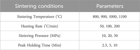
TABLE 1. Sintering conditions.
Apparent densities of sintered samples were measured using specific gravity (Archimedes’ method with water and air as comparative fluids), while the envelop densities were determined from the dry weight and volume measurements. The ideal density, used to determine relative density, was calculated based on rule-of-mixtures with volume fractions and ideal density of components determined through X-ray diffraction (XRD). Standard metallographic grinding and polishing were performed on sintered compacts to mirror surface finishes for phase identification and microstructure characterization. XRD measurements were performed employing an D8 Advance diffractometer (Bruker, United States) operating at 40kV and 40 mA equipped with a copper target. Rietveld analysis was performed in TOPAS (Bruker, United States) to quantify the phase fractions after sintering. With chosen x-ray parameters the sample volume being probed is subsurface, mitigating any potential surface-to-volume measurement issues. The quantitative phase analysis procedure performed directly on the experimental XRD patterns, to determine the phase fractions within the different CMCs, was the standard Hill and Howard (ZMV) approach (Hill and Howard, 1987). This is a common standardless XRD method and assumes that all phases (i.e., the entire specimen) are crystalline.
Microstructure and metallographic investigations were performed using a high-resolution field emission scanning electron microscope (SEM, JEOL 7600F, Japan) operating at 15 kV at a working distance of 15 mm and a regular inverted metallurgical microscope (Pace Technologies, IM-5000, United States). Samples for transmission electron microscopy (TEM) were prepared through a typical focused ion beam (FIB) lift-out procedure in a Helios G5 Dual Beam SEM/FIB. TEM and energy dispersive X-ray spectroscopy (EDS) were collected using an FEI Talos 200x operating at 200 keV. The thermal diffusivity of the sintered ceramic matrix composite (CMC) was measured using a Netzsch laser flash apparatus (LFA 467HT) with temperatures from room temperature to 200°C under the argon gas environment. The thermal conductivity was calculated using thermal diffusivity measured from LFA and Cp, calculated based on rule of mixtures.
3 Results and discussion
In the following sections, we demonstrate the processing and sintering parameter optimizations leading to dense ceramic matrix composites consisting of HfH2 entrained within an MgO host matrix.
3.1 Green body density optimization
Monolithic grain size powders result in lower green body packing densities due to intrinsic open space between large powder particles. As shown in Figure 4, green bodies pressed from monolithic submicron MgO powder alone (Figure 4A) resulted in a packing density of 48.27%, while green bodies pressed from nano MgO powder alone (shown in Figure 4B) yield an even lower packing density of 45.77% due to increased free surface of nano powder. A consequence of these relatively low packing densities is pellet cracking upon cold press unloading, making them unusable for subsequent sintering. However, mixtures of nano and submicron MgO powders improve the packing density and robustness of the green body as shown in Figure 4C. The pressed green body of the bi-modal powder is 1–4% denser than the individual powder compacts. With submicron: nano ratios of 8:2, a maximum packing density of 50.3% was achieved and a stable green body suitable for sintering resulted (shown in Figure 4C). The free space between submicron particles is effectively filled with nano powder, increasing green density and enhancing contacts between powder particles for better surface diffusion and densification of MgO matrix.
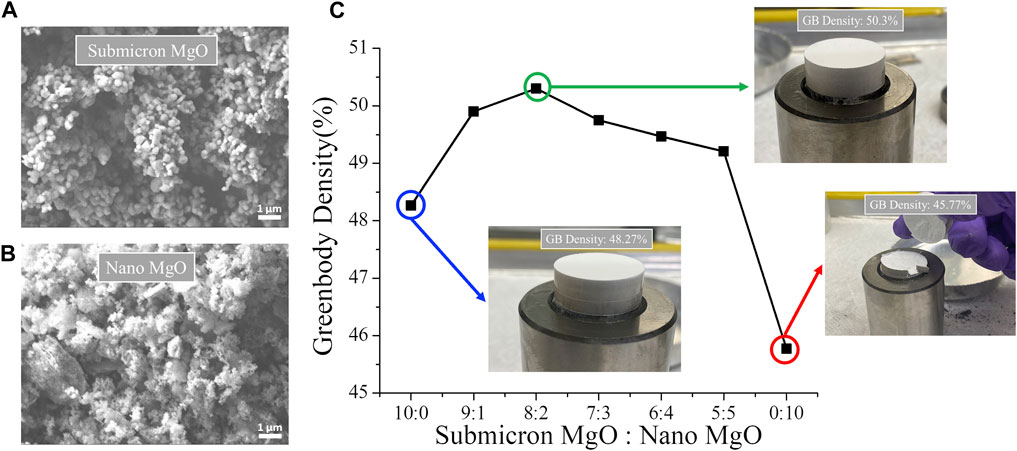
FIGURE 4. The SEM micrographs of (A) submicron and (B) nano MgO powders (C) the green body density as a function of submicron to nano MgO weight ratio and associated cold pressed green body images at 10:0, 8:2 and 0:10 ratios.
3.2 Powder and sintering aid optimization
The ultimate challenge and goal of producing an effective neutron moderating and absorbing shield material is to incorporate the neutron absorbing metal hydride into the composite to a hydrogen level approaching that of water. The primary challenge is whether the minimum temperature for composite processing is consistent with the hydride thermal decomposition temperature. As most hydrides of interest have a plateau pressure of <900°C (Vetrano, 1971) and the list of ceramics that sinter to full density under 1,000°C is extremely limited, forming such a composite is challenging. In previous work by the authors (Cheng et al., 2022), we systematically investigated the effects a range of lithium halides additives on the sintering kinetics of MgO and identified LiF as the most effective sintering aid (Benecke et al., 1967; Carnall, 1967; Hart et al., 1970; Jiang et al., 2017). As shown in Figure 5, the sintering onset temperature of pure submicron MgO powder was reduced from nominally >1,000°C to <700°C by adding 1 wt.% of LiF (∼300°C reduction in sintering temperature). With LiF the sintering to full density occurs at 950°C while pure (i.e., without LiF) submicron MgO did not completely sinter at 1,100°C. Further reductions in the sintering temperature are achieved by replacing micron LiF (∼100 um APS) with nano LiF (<100 nm APS). The sintering behavior of MgO powder mixtures at submicron: nano ratios of 8:2 and 1 wt.% nano LiF are shown in Figure 5. For the powder mixtures, onset of sintering conditions occurs at 400°C (600°C improvement on the submicron MgO compacts), and sintering is complete at 800°C (over 300 °C improvement on the submicron MgO compacts). The significant reduction in sintering temperature is thus attributable to a combined effects of the bimodal MgO particle size distribution, and the homogeneous distribution of nano LiF sintering aid. As discussed in the following sections, this significant reduction in sintering temperature allows processing below that of appreciable disassociation of many hydrides, enabling the sintering of metal entrained hydride phases. Finally, it is noteworthy that the LiF can be considered a fugitive sintering aid as it is essentially completely vaporized during processing.
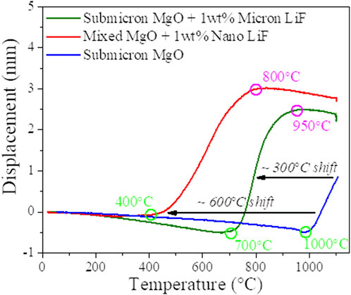
FIGURE 5. DCS ram displacement as a function of heating temperature for the sintering of submicron MgO, mixed MgO with 1wt% nano LiF and submicron MgO with micron LiF.
3.3 Parametric dependence of bulk MgO sintering
The impact of varying the primary sintering parameters on the final monolithic MgO density for optimized bimodal powder mixtures (described above) is shown in Figure 6. For a heating rate of 50 °C/min, holding time of 5 min and sintering pressures of 10 MPa, a monolithic ceramic MgO density of 99% can be achieved after sintering above 850 °C (Figure 6A). As suggested above, achieving a fully dense MgO ceramic absent of micro-cracking and interconnected porosity is a requirement for use of MgO as a matrix of an entrained hydride shield matrix. In this way the matrix can serve to entrain and contain the hydrogen within the shield composite. Lower matrix densities (∼96%) are obtained at an 800°C sintering temperature and appear also to be free of microcracking and interconnected porosity. Increasing the heating rate (with fixed maximum temperature of 800°C) from 25°C/min to 100°C/min leads to a preferred increase in final density (Figure 6B). At a heating rate of 100°C/min, a 98.5% density was obtained. The effect of sintering pressure with optimized heating rate and fixed 800°C maximum temperature is shown in Figure 6C. Composites with densities greater than 99% are achievable with a pressure of 20 MPa (and above). A 5 min peak temperature holding time (Figure 6D) is sufficient to further densify composites. In summary, processing parameters have been optimized to yield a range of dense MgO ceramics.
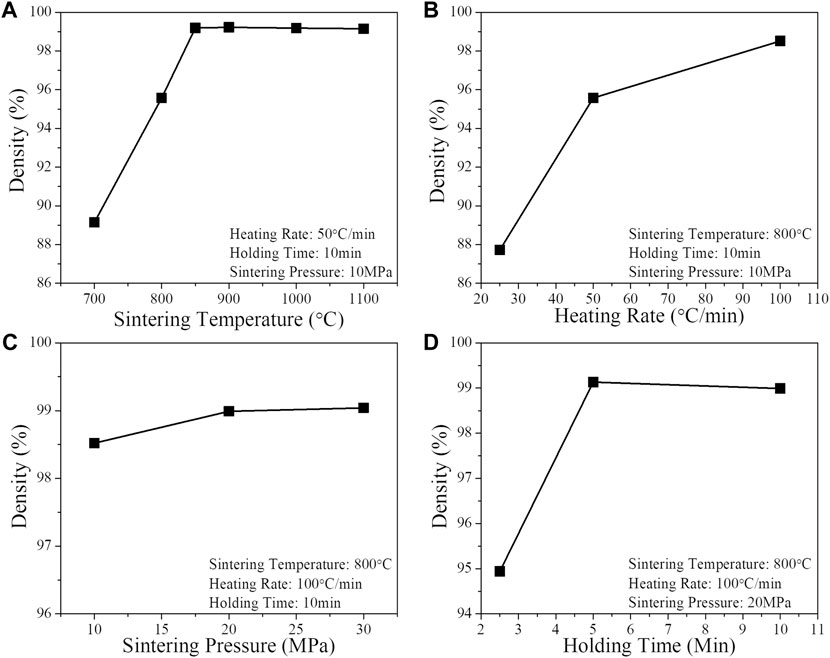
FIGURE 6. Parametric dependence of Bulk MgO Sintering (A) sintering temperature, (B) heating rate, (C) sintering pressure, (D) holding time.
3.4 Entraining HfH2 within MgO
A primary motivation for the suppression of sintering temperature is to open a processing window which minimizes the dissociation of MHx hydrides, where M is a metal of large neutron absorption cross section such as europium, gadolinium, or hafnium (Vetrano, 1971): HfH2 being the primary metal hydride of interest in this processing study. Leveraging the processing described in Sections 3.1–3.3, here we describe the entrainment of HfH2 particles to MgO to form a shield composite. The XRD pattern for MgO-LiF matrix with 25, 40, and 55Vol% HfH2 originally in mixed green bodies are shown in Figure 7A. The phases in the green body are identified as MgO, HfH2, minor HfO2 and LiF. It is again noted that the LiF is primarily a fugitive sintering aid, having largely vaporized during processing. The volume fractions obtained from the XRD quantitative analysis are shown in Figure 7B. The weight fractions obtained from the XRD are equivalent to the values calculated using the stoichiometry. The error bars in Figure 7B are quantitative errors associated with the non-linear least-squares fit of Rietveld refinement.
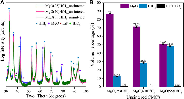
FIGURE 7. (A) XRD pattern of MgO+25Vol%HfH2, MgO+40Vol%HfH2 and MgO+55Vol%HfH2 green body; (B) Weight fraction of phases determined from XRD.
Figure 8 shows sintering traces for MgO + 25Vol% HfH2 (final density, and porosity) highlighting the differences in the sintering onset temperature relative to the monolithic MgO. As seen, the inclusion of the hydride causes a delay in onset sintering from 400°C to 700°C. We note that the thermal conductivity of the powder mixture is a critical factor in the sintering process (Guillon et al., 2014). As MgO has a relatively high thermal conductivity of ∼44 (W/m⋅K) (Cheng et al., 2022) as compared to HfH2 at ∼10 (W/m⋅K) (Ito et al., 2009) the higher onset sintering temperature can, at least in part, be attributed to a processing thermal gradient from sample periphery of as large as 100°C (Anselmi-Tamburini et al., 2005). The delay in sintering from Figure 8A is thus attributed to the lower thermal conductivity of HfH2 depressing the effective thermal conductivity of the green body. The apparent and envelope densities calculated as a function of sintering are shown in Figure 8B. The envelop density and open porosity monotonically increase and decrease, respectively, with temperature. The contributions of the closed and open porosity as determined by a combination of specific gravity and dimensional analysis are shown in Figure 8C.
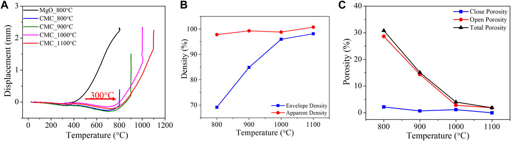
FIGURE 8. (A) DCS ram displacement as a function of heating temperature for the sintering of monolithic MgO and MgO+20Vol%HfH2 CMC at different sintering temperature. Upper plateau pressure of HfH2 after Vetrano (1971) (B) Density and (C) Porosity of CMC as a function of sintering temperature.
XRD patterns for the MgO + 25Vol% HfH2 CMC samples sintered via DCS at different temperatures are shown in Figure 9A. The XRD patterns show that post sintering, hydrogen remains in the composite, albeit in both the original HfH2 structure and in HfH<2 phases even up to a final sintering temperature of 1,100 °C. The primary lower H-phase has been identified as HfH1.4, consistent with the known phase diagram (Dottor et al., 2023). Noting that for similar thermal histories (cf Table 1), complete powder dehydriding occurs for naked (non-composited) HfH2 powder after heating to above 800 °C, this confirms that compositing retards HfH2 decomposition kinetics, even prior to full matrix densification. In addition to the main composite species (HfH2, HfHx and MgO), HfO2 and minor metallic Hf phases were quantified and attributed to hydride decomposition. Metallic Hf is only observed in specimens sintered above 800°C. The quantitative phases determined from the XRD analysis are shown in Figure 9B. The HfH2 phase decreases from 11.58 vol.% to 3.46 vol.% after 1,000 °C. The fraction of HfO2 increases with increasing sintering temperature (relative to the green body).
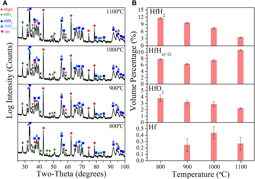
FIGURE 9. (A) XRD patterns of MgO+25Vol%HfH2 samples sintered at 800°C, 900°C, 1,000°C, and 1,100°C. (B) Quantitative XRD analysis results of HfH2, HfHx, HfO2 and Hf phases.
The matrix density of the compacts was found to be >99% relative to bulk value based on rule-of-mixtures. This is of particular importance as a key design assumption for this composite system is the ability to contain the hydride during reactor operation when subjected to heat and irradiation. As compared to a monolithic, or “massive” hydride, the design principle of entrainment significantly restricts hydrogen into a low mobility matrix. This would be compromised by high levels of porosity, or interconnected small porosity, which is seen not to be the case as evidenced by the measured density and optical and x-ray tomographic imaging of the MgO matrix. The XRD patterns for MgO-LiF + 25, 40, and 55Vol% HfH2 CMC samples sintered at 1,100 °C are shown in Figure 10A. The phases in the sintered CMC’s are again identified as MgO, HfH2, HfHx (<2), Hf and HfO2. The HfHx (<2) phase identified as HfH1.4 is observed in both all specimens. The volume fractions quantified from the XRD analysis are shown in Figure 10B. The combined volume fractions of HfH2 and HfHx (<2) obtained after sintering are reduced when compared to the green body specimen, acknowledging minor decomposition of hydride to Hf and HfO2. Moreover, upon increasing the HfH2 concentration to 55 vol.%, the retained HfH2 phase (i.e., the amount of HfH2 that remains HfH2) increases from 3.43% to 16.38%. The hydrogen content quantified from the XRD analysis for the as-sintered CMCs is summarized in Table 2, with reference to the hydrogen content in bulk HfH2 (Vetrano, 1971), lower hydrogen containing HfHx phases (Dottor et al., 2023), and H2O. The high hydrogen content in the solid shield CMCs compare favorably when compared to the hydrogen in water. Table 2 demonstrates that this approach can be utilized to fabricate CMCs with controllable hydrogen content.
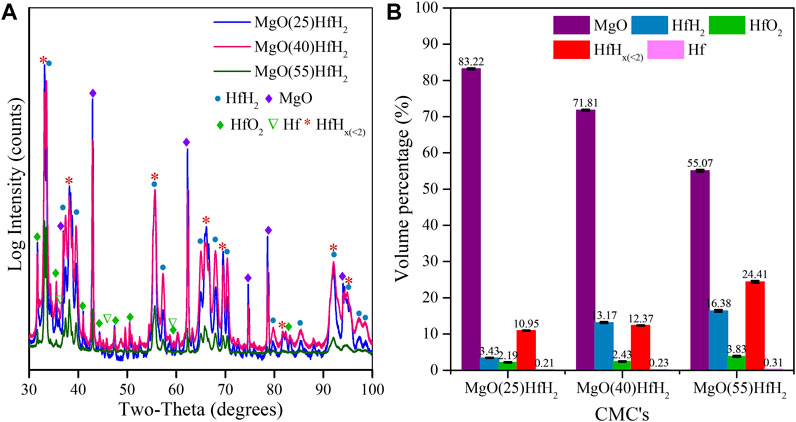
FIGURE 10. (A) XRD pattern of MgO+25Vol%HfH2, MgO+40Vol%HfH2 and MgO+55Vol%HfH2; (B) Weight fraction of phases determined from XRD.
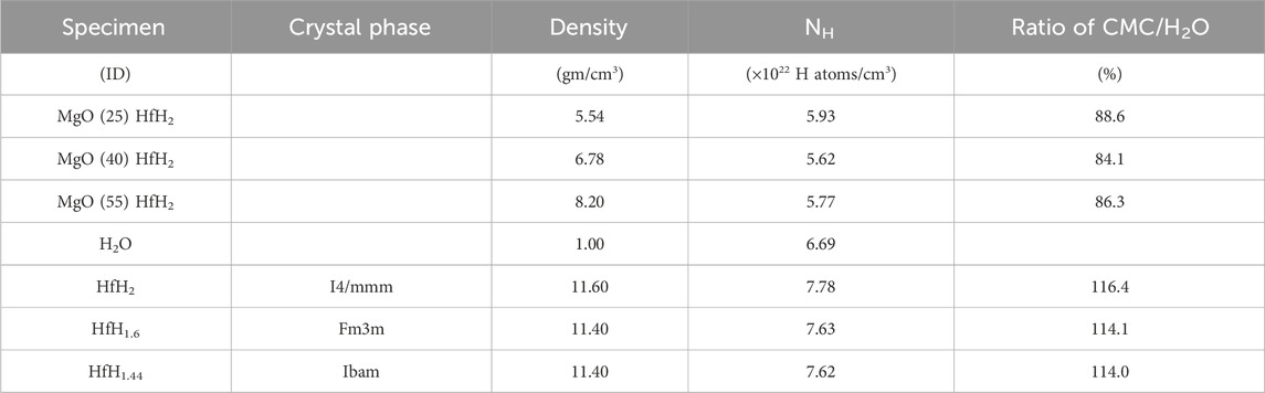
TABLE 2. Experimentally determined densities for CMCs, hydrogen atom density NH and ratio of H density relative to H2O. Values for HfH2 and HfHx phases are included for reference.
Representative SEM micrographs and XCT cross section for CMCs sintered at 1,100°C are shown in Figure 11. The SEM micrographs and XCT volume show crack-free, dense matrix material with heterogeneous distributions of the metal hydride particles (white contrast in SEM images and yellow contrast in XCT) dispersed within the MgO matrix (grey contrast). Both SEM and XCT also show that the MgO matrix is void-free with no apparent interconnected porosity. The high-resolution SEM micrograph in Figure 11A shows a sub-micron particle (discussed below) and an average MgO grain size less than a few microns.
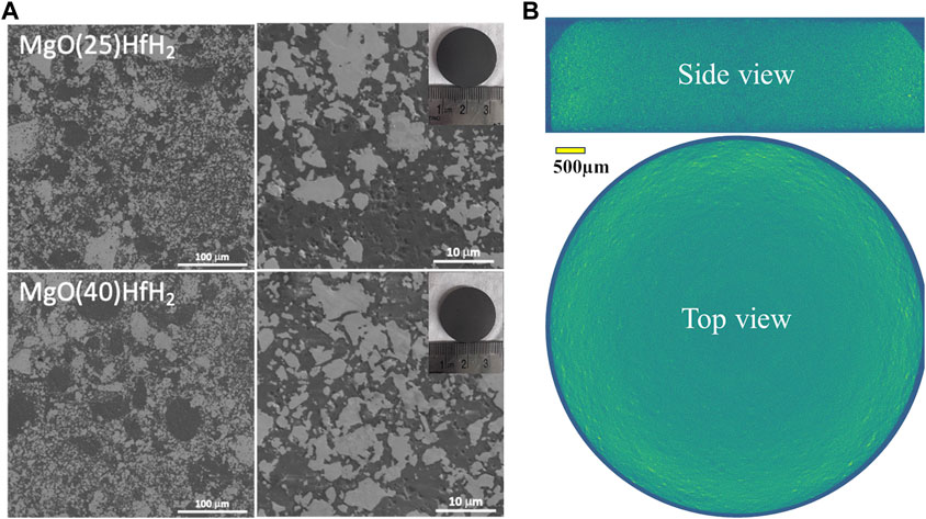
FIGURE 11. (A) SEM micrographs of MgO+25%HfH2 and MgO+40%HfH2 CMC sample sintered at 1,100°C, (B) shows a representative XCT reconstruction through the volume of the MgO+25%HfH2 CMC specimen. The inset in (A) shows optical images of the polished CMC samples.
Figure 12A shows the BF-TEM micrographs of the MgO+25%HfH2 showing heterogeneous microstructures identical to the SEM results discussed above in Figure 10. The corresponding STEM-HAADF micrograph is given in Figure 12B and highlights variations in chemical compositions. The chemical composition from STEM-EDS is shown in Figures 12C–E for Mg, O, and Hf, respectively. The bimodal size distribution of the Hf-rich phases is apparent. Higher magnification STEM-HAADF and STEM-EDS micrographs shown in Figures 12F, G reveal that the sub-micron particles (as seen above in Figure 12B) are predominately Hf-rich.
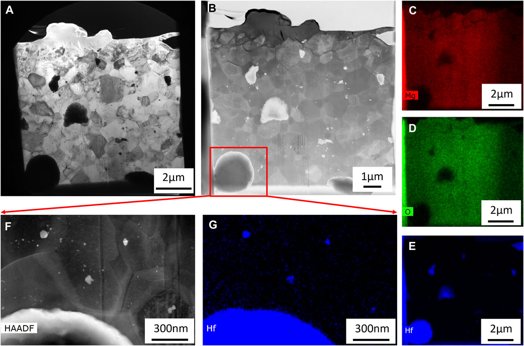
FIGURE 12. (A) BF-TEM and (B) STEM-HAADF micrographs of MgO+25%HfH2 with corresponding STEM-EDS maps of (C) Mg, (D) O, and (E) Hf. A higher magnification (F) STEM-HAADF micrograph with corresponding (G) Hf STEM-EDS map indicates a bimodal distribution of HfH2.
The thermal diffusivity of MgO-HfH2 composites with varying concentrations of HfH2 was determined utilizing the LFA. Subsequently, the thermal conductivity of these composite materials was computed utilizing the following equation: k = α. ρ. Cp(mix). In this equation, the symbol α represents the thermal diffusivity, ρ the density, and Cp(mix) represents the specific heat capacity of the composite material. Cp(mix) of the composite was determined using the rule of mixtures, where Cp values for individual phases were obtained from literature sources and the relative fractions obtained from the quantitative X-ray analysis. For the different phases of HfH2 and HfO2, Cp was calculated using equations provided in the literature, considering the specified temperature range (Stout, 2000; Ito et al., 2009; Low et al., 2021). The Cp values vary for different phases of Hafnium hydride based on the H/Hf ratio (Arita et al., 2008). Additionally for MgO, Cp was acquired from standard data sources (Chase et al., 1998). Cp of the composite (Figure 13A) was found to decrease with increasing concentration of HfH2, which is attributed to weighted averaged effect. Upon increasing the concentration of HfH2, the contribution of its Cp towards calculation of Cp for composite material becomes more significant and hence the overall Cp decreases upon addition of HfH2. Thermal diffusivity and thermal conductivity for MgO-HfH2 composite is shown in Figure 13B. Both the values tend to decrease with increasing temperature and with increasing concentration of HfH2. As seen from SEM and TEM results discussed earlier, there is a heterogeneous distribution of HfH2, which acts as phonon scattering centers. These centers reduce the free flow of phonons. Moreover, as seen from literature, HfH2 (Ito et al., 2009) has lower thermal conductivity than MgO (Cheng et al., 2022), it can act as an insulating phase that hinders heat transfer within the composite, thereby reducing the thermal diffusivity and thermal conductivity.
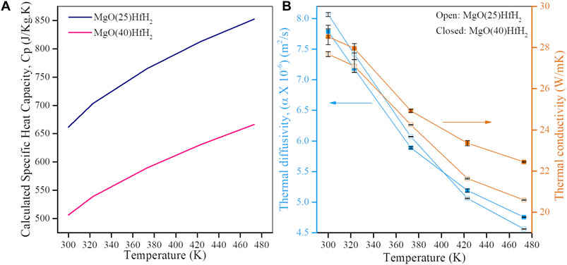
FIGURE 13. (A) Specific heat capacity, Cp of MgO-HFH2 composites. (B) Thermal diffusivity and thermal conductivity for the MgO+25%HfH2 and MgO+40%HfH2 CMC’s.
Figure 14 provides insight into how effective this simultaneously moderating and absorbing composite shield can be, showing the impact of MgO entrained HfH2 volume fraction on the damaging neutron flux to the inboard high-temperature superconducting toroidal field coils of an compact fusion system. An ARC-like radial build was used to build an axisymmetric constructive solid geometry (CSG) model of a tokamak that included 60 cm of dedicated neutron shielding between a FLiBe blanket and the toroidal field (TF) magnets. A variety of present day shield materials were simulated in this neutron shielding region including water, a combination of borated stainless steel and water, boron carbide, and the ENHANCED shield composites. The fast neutron flux (neutrons with energy above 100 keV) was tallied in the first 1 cm of the toroidal field coil winding pack at the inboard midplane. This represents the highest flux experienced by the HTS material in the TF magnets and thus is the appropriate flux to use when assessing TF magnet lifetime. The neutron flux is normalized to 500 MW of fusion power. As shown in Figure 14 the metal and ceramic matrix ENHANCED shield composites begin to out-perform standard shielding materials at a modest HfH2 entrainment fraction of ∼10% by volume. Clearly these materials substantially outperform equivalent thickness of water, the ITER-standard borated steel water/water, or monolithic B4C shield materials, achieving a notional fast neutron flux goal of <5 × 10⁻⁹ n/cm2-s (E > 0.1 MeV) However, as indicated by the asterisks on the MgO-HfH2 curves, these are for hydrogen loading consistent with prefabricated hydrogen loadings, not considering processing hydrogen loss. XRD results for the MgO+25%HfH2 MgO+40%HfH2 and MgO+55%HfH2 CMC’s show considerable (majority) retention of the entrained hafnium hydride phase after sintering at high temperature. The high hydrogen fractions retained after processing, even after phase transformation from HfH2 to HfHx, compare favorably with the hydrogen content in water.
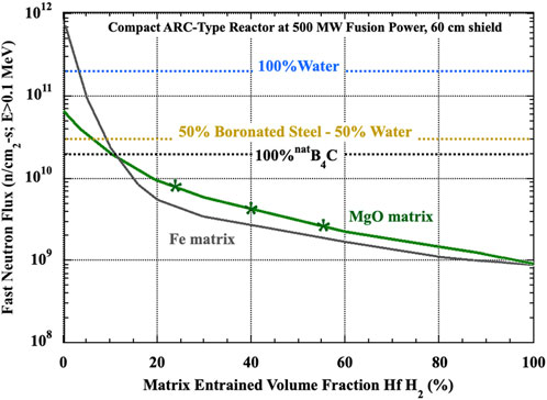
FIGURE 14. Fast Neutron Flux corresponding to the volume fraction of HfH2 entrained in the matrix.
The thermal conductivity of the composite CMCs was found to decrease with increasing concentration of HfH2 as expected given the lower conductivity of the hydride phase. This work provides positive encouragement for next-step investigation of this composite shield system which includes scaling to larger plates and loss of hydrogen from bulk materials through long-duration thermal and irradiation environmental testing, both of which are underway.
4 Summary of the developed technology
In this work we demonstrate the successful fabrication of dense monolithic two-phase ceramic shield composites by low-temperature co-sintering of MgO with HfH2. It is shown that a bimodal particle size distribution of MgO combined with the use of nano LiF opens a processing window to fabricate this new class of shield composite. Crack-free MgO-HfHx composite shielding has been shown to be sintered at a range of temperatures up to and above 1,000 °C with fully dense MgO matrix. The choice of, and ability to use MgO as matrix material, offers a potential (yet unproven) for an irradiation stable and low-permeation matrix capable of relatively high temperatures. During processing the starting HfH2 does undergo dissociation, but this loss of hydrogen is relatively minor and is retarded by the MgO matrix. The amount of hydrogen retention, both during processing, over long-term in-reactor use, and in the event of off-normal reactor transients will be important information determining the ultimate application of this class of shielding. As such, the authors view this material as being in an early stage of development, requiring significant additional study in a range of area including long-term aging and irradiation effects on hydrogen retention, overall effects of irradiation on the mechanical integrity, and general scaling and production issues.
Data availability statement
The raw data supporting the conclusions of this article will be made available by the authors, without undue reservation.
Author contributions
DB: Investigation, Methodology, Writing–original draft, Formal Analysis. BC: Data curation, Investigation, Writing–review and editing. DS: Data curation, Formal Analysis, Investigation, Methodology, Supervision, Writing–review and editing. WC: Investigation, Writing–review and editing. NR: Investigation, Writing–review and editing. JT: Investigation, Supervision, Writing–review and editing. LS: Conceptualization, Funding acquisition, Investigation, Methodology, Project administration, Resources, Supervision, Writing–review and editing, Formal Analysis, Writing–original draft.
Funding
The author(s) declare that no financial support was received for the research, authorship, and/or publication of this article.
Acknowledgments
This work was performed under the auspices of the Department of Energy ARPA-E GAMOW (Galvanizing Advances in Market-Aligned Fusion for an Overabundance of Watts) program through contract with the Research Foundation for the State University of New York.
Conflict of interest
The authors declare that the research was conducted in the absence of any commercial or financial relationships that could be construed as a potential conflict of interest.
Publisher’s note
All claims expressed in this article are solely those of the authors and do not necessarily represent those of their affiliated organizations, or those of the publisher, the editors and the reviewers. Any product that may be evaluated in this article, or claim that may be made by its manufacturer, is not guaranteed or endorsed by the publisher.
References
Anselmi-Tamburini, U., Gennari, S., Garay, J. E., and Munir, Z. A. (2005). Fundamental investigations on the spark plasma sintering/synthesis process: II. Modeling of current and temperature distributions. Mater. Sci. Eng. A 394 (1), 139–148. doi:10.1016/j.msea.2004.11.019
Arita, Y., Ogawa, T., Tsuchiya, B., and Matsui, T. (2008). Heat capacity measurement and DSC study of hafnium hydrides. J. Therm. Anal. Calorim. 92 (2), 403–406. doi:10.1007/s10973-007-8960-4
Benecke, M. W., Olson, N. E., and Pask, J. A. (1967). Effect of LiF on hot-pressing of MgO. J. Amer. Ceram. Soc. 50 (7), 365–368. doi:10.1111/j.1151-2916.1967.tb15132.x
Carnall, E. (1967). The densification of MgO in the presence of a liquid phase. Mater. Res. Bull. 2 (12), 1075–1086. doi:10.1016/0025-5408(67)90135-3
Cg, W., and Jg, M. (2017). Neutron and gamma flux distributions and their implications for radiation damage in the shielded superconducting core of a fusion power plant. Nucl. Fusion 57, 116032. doi:10.1088/1741-4326/aa7e3e
Chase, M. W. J., Curnutt, J. L., Downey, J. R., McDonald, R. A., Syverud, A. N., and Valenzuela, E. A. (1998). JANAF thermochemical tables, 1982 supplement. J. Phys. Chem. Ref. Data 11, 695–940. doi:10.1063/1.555666
Cheng, B., Duchnowski, E. M., Sprouster, D. J., Snead, L. L., Brown, N. R., and Trelewicz, J. R. (2022). Ceramic composite moderators as replacements for graphite in high temperature microreactors. J. Nucl. Mater. 563, 153591. doi:10.1016/j.jnucmat.2022.153591
Clinard, F. W., Hurley, G. F., and Hobbs, L. W. (1982). Neutron irradiation damage in MgO, Al2O3 and MgAl2O4 ceramics. J. Nucl. Mater. 108&109, 655–670. doi:10.1016/0022-3115(82)90538-4
Creely, A. J., Greenwald, M. J., Ballinger, S. B., Brunner, D., Canik, J., Doody, J., et al. (2020). Overview of the SPARC tokamak. J. Plasma Phys. 86 (5), 865860502. doi:10.1017/s0022377820001257
Dottor, M., Crivello, J.-C., Laversenne, L., and Joubert, J.-M. (2023). Experimental determination of the H–Hf phase diagram using in situ neutron diffraction. J. Alloys Comp. 937, 168353. doi:10.1016/j.jallcom.2022.168353
Federici, G., Vachmann, C., Barucca, L., Biel, W., Boccaccini, L., Brown, R., et al. (2018). DEMO design activity in europe: progress and updates. Fusion Eng. Des. 136, 729–741. doi:10.1016/j.fusengdes.2018.04.001
Gryaznevich, M., and Asunta, O. (2017). Overview and status of construction of ST40. Fusion Eng. Des. 123, 177–180. doi:10.1016/j.fusengdes.2017.03.011
Guillon, O., Gonzalez-Julian, J., Dargatz, B., Kessel, T., Schierning, G., Räthel, J., et al. (2014). Field-assisted sintering technology/spark plasma sintering: mechanisms, materials, and technology developments. Adv. Eng. Mater. 16 (7), 830–849. doi:10.1002/adem.201300409
Hart, P. E., Atkin, R. B., and Pask, J. A. (1970). Densification mechanisms in hot–pressing of magnesia with a fugitive liquid. J. Am. Ceram. Soc. 53 (2), 83–86. doi:10.1111/j.1151-2916.1970.tb12015.x
Hill, R. J., and Howard, C. J. (1987). Quantitative phase analysis from neutron powder diffraction data using the Rietveld method. J. Appl. Crystallogr. 20 (6), 467–474. doi:10.1107/s0021889887086199
Hurley, G. F., Kennedy, J. C., Clinard, F. W., Youngman, R. A., and McDonell, W. R. (1981). Structural properties of MgO and MgAl2O4 after fission neutron irradiation near room temperature. J. Nucl. Mater. 103&104, 761–765. doi:10.1016/0022-3115(82)90690-0
Ito, M., Kurosaki, K., Muta, H., Uno, M., Konashi, K., and Yamanaka, S. (2009). Thermal conductivity of hafnium hydride. J.Nucl. Sci. Technol. 46 (8), 814–818. doi:10.1080/18811248.2007.9711590
Jiang, N., Xie, R.-j., Liu, Q., and Li, J. (2017). Fabrication of sub-micrometer MgO transparent ceramics by spark plasma sintering. J. Eur. Ceram. Soc. 37 (15), 4947–4953. doi:10.1016/j.jeurceramsoc.2017.06.021
Kuang, A. Q., Cao, N. M., Creely, A. J., Dennett, C. A., Hecla, J., LaBombard, B., et al. (2018). Conceptual design study for heat exhaust management in the ARC fusion pilot plant. Fusion Eng. Des. 137, 221–242. doi:10.1016/j.fusengdes.2018.09.007
Low, J. J., Paulson, N. H., D'Mello, M., and Stan, M. (2021). Thermodynamics of monoclinic and tetragonal hafnium dioxide (HfO2) at ambient pressure. Calphad 72, 102210. doi:10.1016/j.calphad.2020.102210
Snead, L., Brown, N., Trelewicz, J., Ang, C., Cheng, B., Hu, X., et al. (2019). Fabrication of two-phase composite moderators as potential lifetime reactor components. Transactions 121 (1), 1445–1447.
Snead, L., Sprouster, D., and Trelewicz, J. (2023). CERAMIC MATRIX COMPOSITES ENABLE THROUGH METAL HALIDE ASSISTED SINTERING. U. S. Pat. App 17/790, 086.
Snead, L., and Trelewicz, J. (2023). NEUTRON ABSORBING EMBEDDED HYDRIDE SHIELD. U. S. Pat. App 17/914, 019.
Snead, L. L., Sprouster, D., Cheng, B., Brown, N., Ang, C., Duchnowski, E. M., et al. (2022). Development and potential of composite moderators for elevated temperature nuclear applications. J. Asian Ceram. Soc. 10, 9–32. doi:10.1080/21870764.2021.1993592
Sorbom, B. N., Ball, J., Palmer, T. R., Mangiarotti, F. J., Sierchio, J. M., Bonoli, P., et al. (2015). ARC: a compact, high-field, fusion nuclear science facility and demonstration power plant with demountable magnets. Fusion Eng. Des. 100, 378–405. doi:10.1016/j.fusengdes.2015.07.008
Stout, M. A. R. a. M. G. (2000). Properties of hafnium oxide with respect to its use as a simulant for 238PuO2 in safety studies, los alamos national lab. Los Alamos, NM (United States): LANL.
Taylor, N., Ciattaglia, S., Boyer, H., Coombs, D., Jin, X. Z., Liger, K., et al. (2017). Resolving safety issues for a demonstration fusion power plant. Fusion Eng. Des. 124, 1177–1180. doi:10.1016/j.fusengdes.2017.02.018
Vetrano, J. (1971). Hydrides as neutron moderator and reflector materials. Nucl. Eng. Des. 14 (3), 390–412. doi:10.1016/0029-5493(70)90159-7
Keywords: ceramic matrix composite, fusion shield, compact fusion systems, sintering, thermal conductivity
Citation: Bhardwaj D, Cheng B, Sprouster DJ, Cunningham WS, Rani N, Trelewicz JR and Snead LL (2024) Fabrication of neutron absorbing metal hydride entrained ceramic matrix shield composites. Front. Nucl. Eng. 3:1352667. doi: 10.3389/fnuen.2024.1352667
Received: 08 December 2023; Accepted: 05 February 2024;
Published: 16 February 2024.
Edited by:
Xiaofeng Guo, Washington State University, United StatesReviewed by:
Shingo Tamaki, Osaka University, JapanXing Wang, The Pennsylvania State University (PSU), United States
Copyright © 2024 Bhardwaj, Cheng, Sprouster, Cunningham, Rani, Trelewicz and Snead. This is an open-access article distributed under the terms of the Creative Commons Attribution License (CC BY). The use, distribution or reproduction in other forums is permitted, provided the original author(s) and the copyright owner(s) are credited and that the original publication in this journal is cited, in accordance with accepted academic practice. No use, distribution or reproduction is permitted which does not comply with these terms.
*Correspondence: Lance L. Snead, TGFuY2UuU25lYWRAc3Rvbnlicm9vay5lZHU=