 Immo Schuetz1,2*
 Katja Fiehler1,2
- 1Experimental Psychology, Justus Liebig University, Giessen, Germany
- 2Center for Mind, Brain, and Behavior (CMBB), Philipps-University Marburg, Justus-Liebig University Gießen and Technical University Darmstadt, Giessen, Germany
Introduction: Humans point using their index finger to intuitively communicate distant locations to others. This requires the human sensorimotor system to select an appropriate target location to guide the hand movement. Mid-air pointing gestures have been well studied using small and well defined targets, e.g., numbers on a wall, but how we select a specific location on a more extended 3D object is currently less well understood.
Methods: In this study, participants pointed at custom 3D objects (“vases”) from different vantage points in virtual reality, allowing to estimate 3D pointing and gaze endpoints.
Results: Endpoints were best predicted by an object’s center of mass (CoM). Manipulating object meshes to shift the CoM induced corresponding shifts in pointing as well as gaze endpoints.
Discussion:: Our results suggest that the object CoM plays a major role in guiding eye-hand alignment, at least when pointing to 3D objects in a virtual environment.
1 Introduction
Pointing at a distant location using the outstretched index finger (also referred to as “deictic pointing,” from the linguistic term “deixis” meaning “in reference to a specific place or entity”) is a universal human gesture. Daily life is filled with situations such as having to point out a specific house on the street, an item on a restaurant menu, or indicating a distant landmark in a scenic vista to someone else. Infants learn to point to guide others’ attention to an object of interest starting at around 11 months of age (Leung and Rheingold, 1981; Behne et al., 2012), and pointing is considered a significant step on the road to language and shared attention (Butterworth, 2003; Tomasello et al., 2007).
At its core, performing a free-hand pointing gesture is an eye-hand coordination task: Humans generally bring the target position, index finger tip of their pointing hand, and one of their eyes into linear alignment (Taylor and McCloskey, 1988; Henriques and Crawford, 2002; Herbort and Kunde, 2016, Herbort and Kunde, 2018). This is true even if the head is not currently oriented towards the target, suggesting that the brain is accounting for head-shoulder geometry (Henriques and Crawford, 2002), although earlier work also suggested a shift towards a shoulder-based alignment for targets that are not currently visible (Taylor and McCloskey, 1988). In most cases the hand is aligned with the pointer’s dominant eye (Porac and Coren, 1976), although the eye to use may be selected dynamically depending on the target position in the field of view (Khan and Crawford, 2001, 2003). When used as a means of communication in this way, free-hand pointing directions are sometimes misinterpreted by external observers, likely because pointers base their gesture on the above eye-hand alignment while observers tend to extrapolate the direction of the arm instead (Herbort and Kunde, 2016). Providing observers with additional instruction (Herbort and Kunde, 2018) and assuming the correct visual perspective (Krause and Herbort, 2021) can modulate these effects.
In the past decade, virtual reality (VR) has gained tremendous traction as a research method in experimental psychology and other behavioral fields, in part due to the now wide availability of affordable VR hardware and user-friendly software tools for research (Brookes et al., 2019; Bebko and Troje, 2020; Schuetz et al., 2022). VR now allows to investigate dynamic human behavior in naturalistic but still highly controlled virtual environments (Fox et al., 2009; Scarfe and Glennerster, 2015; Wang and Troje, 2023). Movement tracking systems such as the HTC Vive Trackers (Niehorster et al., 2017) or the computer-vision based hand tracking available, e.g., in Meta (Oculus) Quest devices (Voigt-Antons et al., 2020) allow experimenters to record continuous movement behavior. Further, eye tracking hardware available in a growing number of VR devices such as the HTC Vive Pro Eye (Sipatchin et al., 2021; Schuetz and Fiehler, 2022) or Meta Quest Pro (Wei et al., 2023) allows to measure participants’ visual attention and gaze direction within a virtual environment. These developments make VR a suitable platform for the study of eye-hand coordination tasks (e.g., Mutasim et al., 2020).
It is not surprising, then, that VR has also recently become a widespread method to study free-hand pointing in the field of human-computer interaction (HCI). In this context, the eye-hand alignment vector is often termed Eye-Finger-Raycast (EFRC) due to the fact that a virtual “ray” is computed, beginning at the participant’s eye position and extending along the eye-hand vector. The participant’s intended pointing endpoint can then be determined by finding the intersection of this ray with, e.g., a wall or other object in the virtual environment (Mayer et al., 2015, Mayer et al., 2018; Schwind et al., 2018). Despite systematic errors, EFRC is generally one of the most accurate free-hand interaction gestures (meaning without the use of game controllers or special pointing devices) available in VR (Mayer et al., 2018). Its accuracy can be further improved by providing visual feedback of the endpoint through the use of a cursor (Mayer et al., 2018), and feedback about the position of the pointing limb, such as in the form of an avatar (Schwind et al., 2018). Similarly, taking into account the participant’s dominant eye and hand can improve pointing endpoint accuracy (Plaumann et al., 2018). More recent studies have also investigated VR mitigation strategies for the social misinterpretation effects of pointing mentioned above (Sousa et al., 2019; Mayer et al., 2020).
One thing common to the work mentioned above is that the exact pointing target is usually known beforehand: Experimenters provide small and well-defined targets for the participants to point at, such as LEDs (Henriques and Crawford, 2002; Khan and Crawford, 2003), virtual target points on a wall (Mayer et al., 2015, 2018; Schwind et al., 2018), or marked reference positions on a vertical or horizontal number line (Herbort and Kunde, 2016; Herbort and Kunde, 2018). In all of these cases, the human visuo-motor system does not need to select a specific pointing target from the visual environment and simply needs to align the pointing digit with a known target position as accurately as possible. When considering distant pointing in daily life, however, this target position is often not as clearly defined. For example, when pointing out a specific tree to a friend, do we point to the trunk or crown of the tree, or to an average point encompassing both (for example, the tree’s center of mass)? In the present study, we investigated how humans select an appropriate pointing endpoint when pointing to a spatially extended three-dimensional (3D) target object if an exact target position is not specified.
Existing research on selecting pointing endpoints within a larger shape is fairly sparse. A notable exception comes from Firestone and Scholl (2014), who asked participants to tap a single position within a shape outline presented on a tablet computer. This task yielded a pattern of aggregate taps that clustered around the shape’s medial axis skeleton, with an additional bias toward the shape’s center of mass (CoM).
At the same time, eye movement research consistently suggests that gaze fixations are biased towards the center of entire visual scenes (Central Viewer Bias; Clarke and Tatler, 2014; Tatler, 2007), or towards the center of individual objects within a (2D) scene (Preferred Viewing Location; Nuthmann and Henderson, 2010; Nuthmann et al., 2017; Pajak and Nuthmann, 2013; Stoll et al., 2015). Similarly, initial gaze fixations when viewing individual 2D shapes are known to be attracted to the shape’s CoM (He and Kowler, 1991; Kowler and Blaser, 1995). Interestingly, when shading cues were applied to an image of a 2D object implying a 3D shape, fixation behavior shifted towards the 3D CoM suggested by these depth cues rather than the 2D CoM of the shape outline (Vishwanath and Kowler, 2004). During an action task such as grasping, gaze guidance is also influenced by task demands: Brouwer et al. (2009) found that initial fixations were directed to a 3D object’s CoM, but asking participants to grasp the object shifted gaze towards the planned grasp points on the periphery of the object, i.e., towards task-relevant locations.
Given the above results on eye movements, it becomes clear that the CoM is likely to play a role in pointing target selection on an extended object [although the work by Firestone and Scholl (2014) suggests that this is unlikely to be the only strategy employed by the visuo-motor system]. In the present study, we investigated whether humans indeed point to a target position near the CoM when pointing at 3D objects using their right index finger. We asked right-handed participants to perform natural pointing gestures “as if pointing out the object to someone” to a set of 3D objects in VR. Object shapes were designed to systematically manipulate their CoM along the vertical and horizontal axes, and we recorded pointing and gaze vectors from multiple viewpoints and reconstructed individual 3D target locations for each object. Understanding target location selection for free-hand pointing towards 3D objects can thus serve as a baseline for visuomotor research in more naturalistic virtual environments. In summary, the present study investigated the following hypotheses regarding human free-hand pointing endpoints:
1. Pointing errors to known targets will be more accurate with visual feedback of the pointing finger tip compared to when pointing without visual feedback (Mayer et al., 2018; Schwind et al., 2018).
2. Pointing endpoints for extended 3D objects without an explicitly instructed target location will be predicted best by the object’s center of mass, rather than other features such as the center of the object bounding box (Vishwanath and Kowler, 2004; Brouwer et al., 2009).
3. Systematic manipulations of object center of mass, such as by modifying the object mesh, will yield a corresponding shift in participants’ pointing endpoints.
2 Materials and methods
2.1 Participants
Twenty-five volunteers participated in the study. One participant had to be excluded from analysis due to a data recording error, leaving the final sample at N = 24 (16 female, 8 male; mean age 24.0
2.2 Experimental setup
The experiment took place in a VR lab room (6.6 m

Figure 1. Pointing Task Illustrations. (A) Baseline accuracy task in VR, shown using sphere cursor feedback. Small green sphere (upper right) indicates the target, blue sphere serves as finger tip feedback. (B) Object pointing task in VR, shown using rigid hand model feedback. (C) Calibration of index finger position. Experimenter is holding a second Vive Tracker (left) whose origin point is used to calibrate the participant’s (right) index finger offset. (D) Example pointing gesture using the wrist-mounted Vive Tracker.
A Vive Tracker (2018 model, HTC Corp., Xindian, New Taipei, Taiwan) was fit to the participant’s right wrist using a velcro wrist strap, which was used for continuous recording of hand position and orientation during the experiment. The geometry of the wrist tracker relative to the participant’s index finger tip was calibrated at the start of each experiment by asking participants to hold a natural pointing gesture, then positioning a second Vive Tracker at the finger tip and recording positional and rotational offsets (Figure 1C). Compared to a marker-based motion capture system such as VICON or OptiTrack, this setup was quick to calibrate and kept the index finger tip free of any additional weight or tactile stimuli that might influence the pointing gesture, but did not allow for online tracking of the finger tip relative to the wrist during a trial. Therefore, participants were instructed to hold a pointing gesture that was as natural as possible during calibration, and practice trials were used to ensure a consistent alignment (Figure 1D). In their left hand, participants held a game controller (Valve Index; Valve Corp., Bellevue, WA, United States) which was used to acknowledge instructions shown during the experiment and confirm pointing endpoints using the trigger button. Finally, the eye tracker built into the HMD recorded eye positions and gaze directions at 90 Hz, binocularly and separately for each eye (Sipatchin et al., 2021; Schuetz and Fiehler, 2022).
The study protocol was implemented using the Vizard VR platform (version 6.3; WorldViz, Inc., Santa Barbara, CA, United States) and our in-house toolbox for behavioral experiments using Vizard (vexptoolbox version 0.1.1; Schuetz et al., 2022). It was run on an Alienware desktop PC (Intel Core i9-7980XE CPU at 2.6 GHz, 32 GB RAM, Dual NVidia GeForce GTX1080 Ti GPUs). Due to the ongoing COVID-19 pandemic at data collection time, participants and experimenter wore surgical face masks, and single-use paper masks were placed on the HMD for each participant.
2.3 3D target objects
A collection of six different 3D objects (“vases”) were created using Blender (version 2.83; Stichting Blender Foundation, Amsterdam). Starting from a cylindrical base shape, we systematically manipulated the object’s CoM: Along the vertical (Y) axis, the bulk of the object’s shape could be positioned high, near the middle, or low, and objects could either be symmetric or asymmetric along the horizontal (X) axis. To create the asymmetric objects, part of the symmetric object mesh was deformed so that the object’s CoM was moved away from an x-axis position of zero. The resulting set of objects provided a 3 (vertical)

Figure 2. 3D objects (“vases”) used in the experiment, grouped by center of mass position (high, middle, low) and rotational symmetry (symmetric, asymmetric). Colors for illustration purposes only (not corresponding to exact colors used in the experiment). (A) High/Sym (B) High/Asym (C) Middle/Sym (D) Middle/Asym (E) Low/Sym (F) Low/Asym.
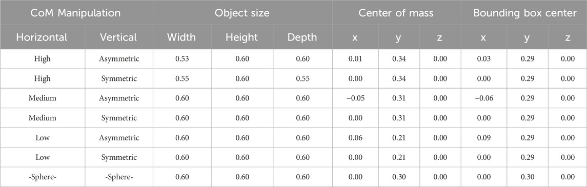
Table 1. Object dimensions and centers of mass and bounding box for each object. All values in meters.
2.4 Object pointing task
Each participant performed the pointing task in three sessions which were run in counterbalanced order. Sessions differed in the type of visual feedback participants received about their index finger position: Either a blue cursor sphere (2.5 cm diameter) aligned with the participant’s calibrated index finger tip; a rigid 3D hand model of a pointing hand (cf. Figure 1B), aligned with the finger tip and wrist position and orientation during the task, or no visual feedback at all. We included the hand model because no experimental setup that could accommodate fully articulated hand tracking was available for this study, but prior work indicated higher pointing accuracy with cursor and hand or body visualizations (Schwind et al., 2018). Each session began with a calibration of the alignment between the wrist Vive Tracker and index finger tip, allowing to set the position of the sphere cursor or virtual hand index finger tip to the calibrated location. This was followed by the built-in calibration routine of the Vive Pro Eye eye tracker. A five-point gaze validation procedure was performed after calibration to measure eye tracker calibration accuracy for each session (Schuetz et al., 2022). Participants were able to take a break and remove the VR headset in between sessions if desired.
Next, baseline pointing accuracy for both gaze and pointing endpoints was assessed by presenting nine calibration targets (bright green spheres, 5 cm diameter; cf. Figure 1A) on the back wall of the virtual room, arranged in a
After the baseline trials, participants performed the object pointing task (Figure 1B). Each of the seven objects (six vase shapes and control sphere) was presented twice from each of five different viewpoints. Viewpoints were defined by the object’s angle of rotation around the vertical axis (yaw angles: 0°, 90°, 135°, and 215°) as well as the object’s vertical position as defined by the height of the central marble column (0.8 m or 1.2 m). Each object was presented from 0°, 90°, and 215°at a height of 0.8 m, and additionally from 0°, and 135° at a height of 1.2 m. In each trial, participants first saw an empty room containing only a fixation target (red sphere presented at eye level on the back wall; 5 cm diameter). After 0.5 s of successful fixation, the sphere disappeared and the column and object appeared in the room. Participants were instructed to look and point at the object with their right hand as naturally as possible, “as if they were pointing out the object to someone else,” with no constraints on location, speed or accuracy. After reaching their final pointing pose, participants pressed the trigger button on the controller in their left hand to confirm, ending the trial. The scene then faded to black and back to an empty room over an inter-trial interval (ITI) of 1.2 s. Each participant performed 18 baseline and 70 pointing trials per session. Sessions typically lasted less than 10 min, and the whole experiment took ca. 30 min to complete.
2.5 Data processing
Data for each participant and session were imported and separated into baseline and pointing trials. Gaze vectors were reported by the eye tracker as 3D direction vectors originating at either eye, or at a combined (“cyclopean”) eye position. Pointing vectors for each trial were computed by calculating a 3D vector originating at the participant’s measured eye position for this trial and extending through the calibrated index finger tip position into the scene. We computed these Eye-Finger-Raycasts (EFRC) separately for each eye and additionally using the averaged eye position and gaze vector. Because participants’ eye dominance was tested before the experiment, we were also able to select vectors specifically from the participant’s dominant eye in an additional analysis.
For the baseline pointing accuracy task, we measured the point of intersection between the pointing vector (EFRC) and back wall of the virtual room, then computed baseline pointing accuracy as the Euclidean distance between the wall intersection point and current target position at the moment the controller button was pressed down. Trials without valid gaze data at button press due to blinks were removed (17 trials), as were trials where the wall endpoint deviated more than 3 standard deviations from the participant mean (16 trials). In total, 1,263 of 1,296 (24 participants
For the object pointing task, we first aligned gaze and pointing vector data across the five different viewpoints. Participants had stood in one place while the object was shown from multiple orientations, therefore all 3D vector data was first rotated around the Y (yaw) axis by the corresponding presentation angle to align the data with the correct object orientation. Trials where pointing vectors intersected with the floor rather than the target object (Y coordinate
Next, we computed average pointing vectors for each participant, object, and viewpoint, leading to five vectors per object and participant. Finally, 3D pointing endpoints were determined by minimizing the sum of perpendicular distances between the common point of intersection and the five averaged pointing vectors using a least squares fit approach. The process is illustrated in Figure 3, which also plots the group-level 3D endpoint (black circle) for one example object by averaging all pointing vectors across participants. In some cases, 3D endpoints could not be computed due to missing individual pointing vectors from the previous step; this affected between 42 (8.3%, left eye) and 55 (10.9%, right eye) out of the 504 total possible 3D endpoints (24 participants
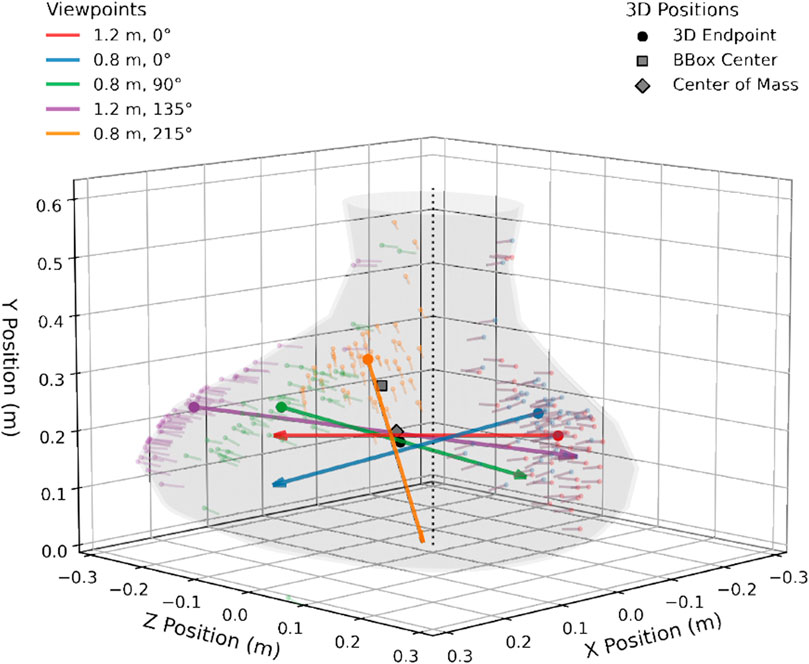
Figure 3. Example of 3D endpoint computation, illustrated using the “low CoM/asymmetric” object. Colors indicate the different viewpoints from which participants pointed at the object. Small, transparent arrows indicate individual trial pointing vectors, large arrows indicate averaged pointing vectors per viewpoint. The 3D endpoint (black circle) is then computed as closest intersection point of the five average pointing vectors. Gray square shows center of object bounding box, gray diamond object center of mass.
The same least-squares method was applied to compute 3D gaze endpoints from averaged gaze direction vectors for each object and viewpoint. Due to a limitation in the experimental code, only vectors based on the binocular gaze position were saved for gaze endpoint analysis. First, we averaged gaze vectors during a time frame of 55.5 ms (5 gaze samples at 90 Hz) immediately before a recorded controller button press and applied viewpoint rotation as detailed above. Gaze vectors were then corrected for outliers using the same criteria as for pointing vectors (see above). Out of 5,040 total trials, a total of 123 trials or 2.4% were removed due to this, and when computing 3D gaze endpoints, 5 endpoints out of 504 (0.99%) could not be estimated.
2.6 Statistical analysis
To investigate whether object CoM predicts observers’ pointing endpoints overall, we computed 3D endpoint errors, defined as the 3D Euclidean distance between the endpoint for each participant and object and the CoM of the corresponding object mesh (assuming uniform object density). To compare to alternative hypotheses, we computed the same error metric also to the center of each object’s bounding box (i.e., a box aligned with the three coordinate axes that fully encompasses the object), as well as an average of errors to a random reference model consisting of a set of 100 random points drawn from within the bounding box. To determine whether shifting the CoM by manipulating the object mesh would induce corresponding shifts in participants’ 3D pointing endpoints, we further analyzed average 3D endpoints using a
Data processing and analysis was performed in Python (v. 3.9) using the trimesh library for 3D object mesh processing and the lstsq function in the numpy package for least-squares fitting. Statistical analyses were performed in Jamovi (v. 2.4.11). We used linear mixed models (LMMs) for statistical analyses and included by-subject random intercepts to capture inter-individual variability. Significant effects are reported on the
3 Results
3.1 Eye tracking accuracy
Average eye tracking calibration accuracy, as measured for each participant and session using the five-point validation procedure, ranged from 0.37° to 1.67°(mean: 0.76°, median: 0.67°). Individual session precision, measured as the standard deviation of gaze samples during the validation procedure, ranged from 0.16° to 1.85°(mean: 0.44°, median: 0.34°).
Note that these values were measured directly after calibration, using target positions that remained static during head movement and covered only a small part of the field of view (FOV). A better estimate of real-world eye tracking accuracy during the task is therefore given by the accuracy of gaze endpoints during the baseline task, measured relative to the baseline pointing targets (spheres; Figure 1A). Average Euclidean distances in meters between gaze endpoints and targets in the baseline task are shown as stars in Figure 4 (gaze endpoints computed using binocular gaze only). Mean gaze error was 0.076 m or 1.24° at the wall distance of 3.5 m, and gaze error was unaffected by visual feedback method (F (2, 1,213) = 1.49; p = .226; cursor: 0.077 m or 1.27°, hand: 0.078 m or 1.28°; no feedback: 0.072 m or 1.18°).
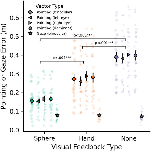
Figure 4. Average baseline pointing and gaze error (m) when pointing to known targets at a distance of 3.5 m. Data shown by visual feedback type (cursor sphere, static hand model, no feedback) and using different eye tracker measures as pointing vector origin: Binocular gaze (diamond), left (left triangle) and right (right triangle) monocular gaze, and using each participant’s dominant eye (circle). Gaze error (m) shown for comparison (stars). Error bars indicate
3.2 Baseline pointing accuracy
Pointing error during the baseline task was defined as Euclidean distance between the intersection of each pointing vector with the far wall and the center of the corresponding target sphere. The resulting error is displayed in Figure 4, separately for each visual feedback method. Pointing vectors (EFRC) could be computed using either the left eye, right eye, or a binocular gaze representation as the vector origin. Additionally, we wanted to determine whether using each participant’s dominant eye would lead to more accurate pointing, as has been suggested previously (Plaumann et al., 2018). Therefore, Figure 4 also compares errors for the different pointing vector origins to determine the most accurate vector type. Finally, the accuracy of measured pointing vectors here fundamentally depends on eye tracking accuracy due to the eye-hand coordination necessary for free-hand pointing, thus Figure 4 also includes gaze error for comparison (distance between the gaze-wall intersection point and each target in the baseline task).
Pointing errors were significantly influenced by visual feedback type (F (2, 5,013) = 1,321.3), p
3.3 3D pointing endpoints
As a first step, we were interested in whether the computed 3D endpoints landed close to each object’s CoM in general and could not be better explained by other reference points, such as an object’s bounding box center or random sampling. Average and per-participant pointing errors for each visual feedback type are shown in Figure 5. We defined 3D pointing errors as the 3D Euclidean distance between endpoints and the corresponding reference model: Either the object’s CoM, center of the object’s bounding box, or average error to 100 randomly selected points from within the bounding box.
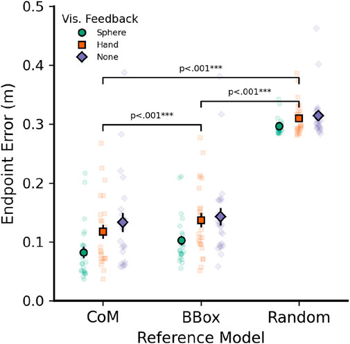
Figure 5. Average pointing errors (3D Euclidean distance between endpoint and corresponding reference point) for three different reference models: Object center of mass (CoM), center of each object’s bounding box (BBox), and average of 100 randomly selected points within the bounding box (Random). Data shown by visual feedback used: Cursor sphere (circles), Hand Model (Squares), or no feedback (Diamonds). All pointing vectors were based on left eye data and sphere visual feedback. Error bars indicate
A
Performing post hoc comparisons (paired t-tests) for the above interaction term, it became clear that the interaction was mainly driven by two reasons: First, errors in the random sampling model did not differ between visual feedback conditions [all t (1,354)
Importantly, the CoM model was always the most accurate predictor of endpoint errors within the cursor sphere feedback condition [CoM vs. bounding box, t (1,354) = −3.848, p = .001; CoM vs. random, t (1,354) = −40.803, p
3.4 Effect of CoM on pointing
Next, we investigated whether computed 3D pointing endpoints would differ significantly between the different objects based on their explicit manipulation of CoM (Figure 2). If CoM plays a major role in free-hand pointing target selection, we hypothesized that a vertical change in object CoM (high, middle, low) should induce corresponding differences in the vertical (Y-axis) component of computed endpoints, while horizontal asymmetry away from the object midline should induce a change in the horizontal (X-axis) component. We only used the six vase shapes that included an explicit manipulation of CoM in this analysis (i.e., excluded the spherical control object). Furthermore, because cursor (sphere) feedback yielded the highest accuracy for both 2D and 3D endpoints, we here only report results from the sphere cursor condition. Figure 6A depicts the X (horizontal) and Y (vertical) components of the resulting 3D endpoints for all six objects, split by vertical CoM position and horizontal symmetry. Panels B and C plot the linear mixed model results when analyzing the vertical (Y) and horizontal (X) coordinates, respectively.
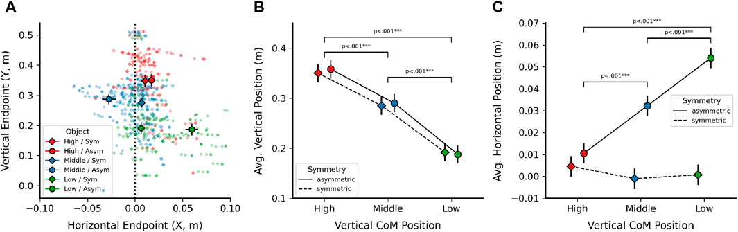
Figure 6. Effects of Center of Mass (CoM) manipulation on 3D endpoints. (A) X and Y coordinates of average 3D endpoints, shown by vertical CoM position (high, middle, low) and horizontal symmetry (diamond: symmetric, circle: asymmetric). Dotted vertical line indicates symmetric object midline. (B) Linear mixed model results (estimated marginal means) for vertical (Y) endpoint position, shown by vertical CoM position and horizontal symmetry. (C) Linear mixed model results (estimated marginal means) for horizontal (X) endpoint position, shown for the same factors as in (B). X coordinates for middle CoM objects were inverted [cf. (A)] to align signs. Error bars in all plots denote
For the vertical component (Figure 6B), there was a clear effect of vertical CoM position [F (2, 114) = 152.25, p
For the horizontal component of pointing endpoints (Figure 6C), we first inverted the X coordinate for the middle CoM object in order to have all horizontal manipulations show positive sign and not potentially mask an effect on endpoint position when averaging. Here, the model yielded significant main effects of vertical CoM position [F (2, 114) = 11.4, p
In post hoc comparisons, all individual object endpoints were different from each other, with the exception of the following: Endpoints for the symmetric objects did not differ significantly from each other [high vs. middle: t (114) = 0.950, p = 1.0; high vs. low: t (114) = 0.655, p = 1.0; middle vs. low: t (114) = −0.295, p = 1.0]. Additionally, endpoints for the high CoM, asymmetric object did not differ from any of the symmetric objects [vs. high/sym: t (114) = 1.002, p = 1.0; middle/sym: t (114) = 1.952, p = 0.501; low/sym: t (114) = 1.657, p = 0.320]. This suggests that for the top CoM object with the smallest CoM manipulation of 0.01 m, any effect of endpoint shift was likely too small to be detected. At the same time, the remaining pairwise comparisons suggest that endpoints were indeed shifted proportional to the object mesh manipulations in agreement with hypothesis 3, and Figure 6A further suggests that all endpoint shifts went into the expected direction (figure shows endpoints before the X coordinate of the middle CoM objects was inverted for LMM analysis).
3.5 Effect of CoM on gaze
Prior work suggests that object CoM, even when only hinted at using shading in a 2D object image, strongly attracts gaze fixations (Vishwanath and Kowler, 2004). Therefore, we also investigated whether shifting object CoM had a direct impact on gaze during pointing. This analysis investigated binocular gaze direction immediately before the moment when participants confirmed their pointing movement using the controller and found a similar overall pattern of results to pointing endpoints. Horizontal (X) and vertical (Y) coordinates of the resulting 3D gaze endpoints are depicted in Figure 7A, together with the LMM results of vertical and horizontal CoM manipulations on vertical (Figure 7B) and horizontal (Figure 7C) gaze endpoint components.
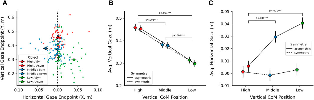
Figure 7. Effects of Center of Mass (CoM) manipulation on estimated 3D gaze endpoints, computed from binocular gaze data using the same methodology as for pointing endpoints. (A) X and Y coordinates of average 3D gaze points, shown by vertical CoM position (high, middle, low) and horizontal CoM symmetry (diamond: symmetric, circle: asymmetric). Dotted vertical line indicates symmetric object midline. (B) Linear mixed model results (estimated marginal means) for vertical (Y) 3D gaze position, shown by vertical CoM position and horizontal symmetry. (C) Linear mixed model results (estimated marginal means) for horizontal (X) 3D gaze position, shown for the same factors as in (B). X coordinates for middle CoM objects were inverted [cf. (A)] to align signs. Error bars in all plots denote
The vertical component of gaze endpoints (Figure 7B) was strongly influenced by vertical object CoM position [F (2, 114) = 107.17, p
As done for pointing endpoints, we inverted the horizontal component for the middle CoM objects to align all CoM manipulations in the same direction. Horizontal gaze endpoints (Figure 7C) were significantly influenced by horizontal symmetry [F (1, 114) = 62.6, p
4 Discussion
In this study, we asked participants to perform free-hand pointing movements to objects in a virtual environment. We then estimated 3D pointing and gaze endpoints for each object by combining vectors from five different viewpoints. Objects were complex 3D shapes and differed in their center of mass (CoM). Endpoints were well predicted by an object’s CoM and shifted accordingly if the CoM was shifted by modifying the object mesh, and this effect was found for both pointing (in agreement with hypothesis 2 and 3) and gaze direction.
We found smaller baseline pointing errors when participants pointed to known targets with visual feedback of their index finger position (cursor sphere, hand model) compared to without any feedback, in agreement with previous work on free-hand pointing (Mayer et al., 2015, 2018; Schwind et al., 2018) and our first hypothesis. However, errors when using a 3D hand model were significantly larger than using the cursor sphere, which was unexpected based on these prior works. A likely explanation is that no experimental setup with fully articulated hand tracking was available for this study, and that the rigid hand model used did not well approximate participants’ actual hand even though hand gestures were similar. This is supported by statements during the informal debrief after the experiment, where the static hand was occasionally labeled as, e.g., “weird” or “unnatural.”
Compared to the work of Schwind et al. (2018), it may also appear that our study produced larger pointing errors; however, it is of note that in their study targets were presented on a screen that was at a distance of 2 m from the participant, while targets here were presented at 3.5 m. When errors are converted to the smaller distance used by Schwind and colleagues via computation of angular errors, the resulting errors for our data were similar to published values (e.g., 0.154 m for cursor pointing at 3.5 m in our study yields 0.088 m when converted to a 2 m distance). Due to this, we are confident that the finger tip calibration method we employed allowed for measurement of realistic pointing vectors despite the possibly lower accuracy compared to a full marker-based tracking system. Because we wanted to investigate object-directed perception and action in the present study, we also refrained from including previously reported methods to compensate for pointing errors Mayer et al. (2015), Mayer et al. (2018). It would be interesting to study whether pointing endpoints still show a strong association with the CoM after applying such error compensation methods.
Previous work also suggests higher accuracy of pointing vectors when the participant’s dominant eye is taken into account (Plaumann et al., 2018), but we did not observe such an effect here. This may be attributable to technical differences in the motion and eye tracking systems used, or to variance in the sample of participants. It is further of note that the lowest pointing errors in our baseline task were found when only vectors based on the left eye were used, and that eye tracking data for the left eye showed the smallest number of invalid trials for the participants tested here. Therefore, a difference in the number of valid trials might explain some of the differences in accuracy and the indiscernible effect of eye dominance; however, the absolute number of trials affected by this difference was quite limited (13/504 trials or 1.6%).
When pointing to 3D objects that differed in their 3D mesh and corresponding CoM, we found that each object’s CoM was the best predictor of average pointing endpoints, compared to the center of an object’s bounding box or a set of 100 randomly sampled positions. There might of course be other relevant reference positions that could be taken into account by the human sensorimotor system, and that were not tested in the above comparison. At the same time, evidence from eye movements suggests the CoM as a major factor in the selection of gaze fixation positions (He and Kowler, 1991; Kowler and Blaser, 1995; Vishwanath and Kowler, 2004), and it is unlikely that pointing, which heavily relies on eye-hand alignment and requires fixating the target object, would utilize a completely different representation.
Beyond a simple Euclidean distance comparison between object-related pointing endpoints and their CoM, endpoints also varied together with CoM when objects were directly manipulated by deforming their 3D mesh, and did so in the expected direction and magnitude. At least for the relatively simple, smooth and convex shapes employed in this study, this suggests a strong association of an object’s 3D CoM with the selection of free-hand pointing target locations. A similar pattern of results was observed for gaze direction during the time when participants indicated that they were pointing at the object, which underlines the strong coupling between eye and hand movements in pointing.
Computed gaze endpoints lay slightly higher than pointing endpoints by about 0.1 m, which could be related to the fact that gaze vectors beginning at eye height intersected the object with a different angle than the eye-hand pointing vector for the same trial. Small angular variations could then translate to a larger change in 3D endpoint position. Alternatively, this difference might be related to the fixation point which participants had to look at before the target object would appear, which was placed higher on the far wall. In fast pointing responses, estimated gaze direction at button press might not have fully caught up with the participant’s gaze fixation due to eye tracker latency. As the pointing vector only uses eye position as its origin, but does not utilize gaze direction, this would affect gaze direction vectors and corresponding endpoints differentially.
Because perception and action mutually interact, the endpoint bias seen here towards an object’s CoM might be linked to perceptual processes, motor execution, or a combination of both factors. Previous work has shown that eye movements are attracted to the implied 3D CoM in 2D shapes with 3D shading (Vishwanath and Kowler, 2004), and our results suggest that this is also true for stereoscopic presentation of 3D shapes in VR. It is likely that the initial eye fixation on an object is then used as the target position to align the eye-hand vector when pointing to the same object. Alternatively, by aligning the hand with the CoM, the motor system might also be able to maximise the object area the finger tip is pointing at to reduce ambiguity or the effects of motor variability. This is especially true for convex objects, where the CoM usually lies within the object mesh. A follow-up experiment could explore what endpoint is selected for concave or more complex shapes where the CoM lies outside the object volume. Object affordances (relating to the tendency to perceive objects specific to how we might interact with them, such as grasping; Gibson, 2014) might also influence the selection of pointing targets, for example, driven by handles or other “interactable” parts of a complex object. Similar affordance effects have been shown to influence eye fixations beyond the initial saccade towards an object (Belardinelli et al., 2015; van Der Linden et al., 2015). Performing a similar pointing task with objects with and without affordances (e.g., a stick compared to a hammer) could shed light on higher level processes involved in pointing target selection.
As a first investigation into endpoint selection when pointing to 3D objects, the present study includes some limitations that might be resolved in future work. For example, due to the limited number of pointing trials for each object and viewpoint (2 per visual feedback condition), we could compute only one 3D endpoint per object and participant in this study. Increasing the number of repetitions for each condition would allow for sampling multiple 3D endpoints per participant and thus estimating individual endpoint variability. Additionally, in the high CoM object used here, the manipulation due to asymmetry was very small (0.01 m) and thus did not yield an object-specific effect despite a trend in the expected direction. In future work, CoM shifts might be more pronounced or span multiple axes to confirm that endpoints fully follow the manipulation. The use of a fully articulated hand tracking system, such as the one now available, e.g., in Meta Quest VR devices, could also increase both accuracy and embodiment of the user’s hand representation, which would allow for a more naturalistic study of free-hand pointing movements in VR. In the present study, we selected the HTC Vive headset and tracker due to familiarity and because our lab room was already set up for this system, whereas a Quest Pro device was not available when the study was conducted. Finally, a VR task such as the one employed here can only serve as a model of naturalistic pointing interactions, but future work might employ motion tracking and 3D-printed objects to allow for a direct comparison between the effects of virtual and real object geometry.
Lastly, the accuracy achieved by eye trackers in VR devices currently still lags somewhat behind that of lab-grade devices such as Eyelink, and variability in the eye tracking signal could conceivably have influenced our pointing and gaze endpoint computations (Schuetz and Fiehler, 2022). For pointing endpoints (Figure 6), vectors were computed using the estimated eye position (relative to the eye tracker in the headset) as the origin and the measured finger tip position as the directional component; therefore, the impact of eye tracker variability on pointing vectors and endpoints is limited to variability in detecting the pupil position within the headset frame of reference, which should be small compared to errors typically observed for estimated gaze vectors. At the same time, it is possible that our reported gaze errors (i.e., stars in Figure 5) are larger than could be expected if we had used a research-grade device. However, due to the fact that gaze errors overall were still much smaller than those recorded for pointing, and the qualitatively very similar pattern of results across Figures 6, 7, we believe that limited eye tracker accuracy had no significant impact on our hypotheses regarding object center of mass.
In summary, our present study provides a first insight into the selection of pointing endpoints on 3D objects in virtual reality, going beyond the current knowledge about pointing to small and well-defined target positions. Our results suggest that object center of mass (CoM) plays a major role in the computation of free-hand pointing vectors in the human sensorimotor system. A better understanding of the computation of implicit pointing targets can also be applied beyond basic research, for example, in ensuring pointing as a communicative gesture is interpreted correctly by bystanders in virtual meetings or educational settings, or correct performance of gestures can be ensured in a medical rehabilitation setting. Taken together, our paradigm and findings open the door to more naturalistic study of human free-hand pointing movements in more complex virtual environments.
Data availability statement
The original contributions presented in the study are publicly available. The data, experimental code, and analysis code for this study are available at https://osf.io/msjhz/.
Ethics statement
The studies involving humans were approved by the local ethics committee at Justus Liebig University, Giessen, Germany. The studies were conducted in accordance with the local legislation and institutional requirements. The participants provided their written informed consent to participate in this study.
Author contributions
IS: Conceptualization, Formal Analysis, Methodology, Software, Writing–original draft, Writing–review and editing. KF: Conceptualization, Funding acquisition, Supervision, Writing–original draft, Writing–review and editing, Methodology.
Funding
The author(s) declare that financial support was received for the research, authorship, and/or publication of this article. This project was supported by the Cluster Project “The Adaptive Mind” funded by the Hessian Ministry for Higher Education, Research, Science and the Arts.
Acknowledgments
The authors thank Leah Trawnitschek for her work on data collection and initial analysis for this study.
Conflict of interest
The authors declare that the research was conducted in the absence of any commercial or financial relationships that could be construed as a potential conflict of interest.
Publisher’s note
All claims expressed in this article are solely those of the authors and do not necessarily represent those of their affiliated organizations, or those of the publisher, the editors and the reviewers. Any product that may be evaluated in this article, or claim that may be made by its manufacturer, is not guaranteed or endorsed by the publisher.
References
Bebko, A. O., and Troje, N. F. (2020). bmltux: design and control of experiments in virtual reality and beyond. i-Perception 11, 204166952093840. doi:10.1177/2041669520938400
Behne, T., Liszkowski, U., Carpenter, M., and Tomasello, M. (2012). Twelve-month-olds’ comprehension and production of pointing. Br. J. Dev. Psychol. 30, 359–375. doi:10.1111/j.2044-835x.2011.02043.x
Belardinelli, A., Herbort, O., and Butz, M. V. (2015). Goal-oriented gaze strategies afforded by object interaction. Vis. Res. 106, 47–57. doi:10.1016/j.visres.2014.11.003
Brookes, J., Warburton, M., Alghadier, M., Mon-Williams, M., and Mushtaq, F. (2019). Studying human behavior with virtual reality: the unity experiment framework. Behav. Res. methods 52, 455–463. doi:10.3758/s13428-019-01242-0
Brouwer, A.-M., Franz, V. H., and Gegenfurtner, K. R. (2009). Differences in fixations between grasping and viewing objects. J. Vis. 9, 18. doi:10.1167/9.1.18
Butterworth, G. (2003). “Pointing is the royal road to language for babies,” in Pointing (New York, NY, United States: Psychology Press), 17–42.
Clarke, A. D. F., and Tatler, B. W. (2014). Deriving an appropriate baseline for describing fixation behaviour. Vis. Res. 102, 41–51. doi:10.1016/j.visres.2014.06.016
Firestone, C., and Scholl, B. J. (2014). “please tap the shape, anywhere you like” shape skeletons in human vision revealed by an exceedingly simple measure. Psychol. Sci. 25, 377–386. doi:10.1177/0956797613507584
Fox, J., Arena, D., and Bailenson, J. N. (2009). Virtual reality: a survival guide for the social scientist. J. Media Psychol. 21, 95–113. doi:10.1027/1864-1105.21.3.95
Gibson, J. J. (2014). The ecological approach to visual perception. classic edition. New York, NY, United States: Psychology press.
He, P., and Kowler, E. (1991). Saccadic localization of eccentric forms. JOSA A 8, 440–449. doi:10.1364/josaa.8.000440
Henriques, D. Y. P., and Crawford, J. D. (2002). Role of eye, head, and shoulder geometry in the planning of accurate arm movements. J. Neurophysiol. 87, 1677–1685. doi:10.1152/jn.00509.2001
Herbort, O., and Kunde, W. (2016). Spatial (mis-) interpretation of pointing gestures to distal referents. J. Exp. Psychol. Hum. Percept. Perform. 42, 78–89. doi:10.1037/xhp0000126
Herbort, O., and Kunde, W. (2018). How to point and to interpret pointing gestures? instructions can reduce pointer–observer misunderstandings. Psychol. Res. 82, 395–406. doi:10.1007/s00426-016-0824-8
Khan, A. Z., and Crawford, J. D. (2001). Ocular dominance reverses as a function of horizontal gaze angle. Vis. Res. 41, 1743–1748. doi:10.1016/s0042-6989(01)00079-7
Khan, A. Z., and Crawford, J. D. (2003). Coordinating one hand with two eyes: optimizing for field of view in a pointing task. Vis. Res. 43, 409–417. doi:10.1016/s0042-6989(02)00569-2
Kowler, E., and Blaser, E. (1995). The accuracy and precision of saccades to small and large targets. Vis. Res. 35, 1741–1754. doi:10.1016/0042-6989(94)00255-K
Krause, L.-M., and Herbort, O. (2021). The observer’s perspective determines which cues are used when interpreting pointing gestures. J. Exp. Psychol. Hum. Percept. Perform. 47, 1209–1225. doi:10.1037/xhp0000937
Leung, E. H., and Rheingold, H. L. (1981). Development of pointing as a social gesture. Dev. Psychol. 17, 215–220. doi:10.1037//0012-1649.17.2.215
Mayer, S., Reinhardt, J., Schweigert, R., Jelke, B., Schwind, V., Wolf, K., et al. (2020). “Improving humans’ ability to interpret deictic gestures in virtual reality,” in Proceedings of the 2020 CHI conference on human factors in computing systems, 1–14.
Mayer, S., Schwind, V., Schweigert, R., and Henze, N. (2018). “The effect of offset correction and cursor on mid-air pointing in real and virtual environments,” in Proceedings of the 2018 CHI conference on human factors in computing systems, 1–13.
Mayer, S., Wolf, K., Schneegass, S., and Henze, N. (2015). “Modeling distant pointing for compensating systematic displacements,” in Proceedings of the 33rd annual ACM conference on human factors in computing systems, 4165–4168.
Mutasim, A. K., Stuerzlinger, W., and Batmaz, A. U. (2020). Gaze tracking for eye-hand coordination training systems in virtual reality. Ext. Abstr. 2020 CHI Conf. Hum. Factors Comput. Syst., 1–9. doi:10.1145/3334480.3382924
Niehorster, D. C., Li, L., and Lappe, M. (2017). The accuracy and precision of position and orientation tracking in the htc vive virtual reality system for scientific research. i-Perception 8, 204166951770820. doi:10.1177/2041669517708205
Nuthmann, A., Einhäuser, W., and Schütz, I. (2017). How well can saliency models predict fixation selection in scenes beyond central bias? a new approach to model evaluation using generalized linear mixed models. Front. Hum. Neurosci. 11, 491. doi:10.3389/fnhum.2017.00491
Nuthmann, A., and Henderson, J. M. (2010). Object-based attentional selection in scene viewing. J. Vis. 10, 20. doi:10.1167/10.8.20
Oldfield, R. C. (1971). The assessment and analysis of handedness: the Edinburgh inventory. Neuropsychologia 9, 97–113. doi:10.1016/0028-3932(71)90067-4
Pajak, M., and Nuthmann, A. (2013). Object-based saccadic selection during scene perception: evidence from viewing position effects. J. Vis. 13, 2. doi:10.1167/13.5.2
Plaumann, K., Weing, M., Winkler, C., Müller, M., and Rukzio, E. (2018). Towards accurate cursorless pointing: the effects of ocular dominance and handedness. Personal Ubiquitous Comput. 22, 633–646. doi:10.1007/s00779-017-1100-7
Porac, C., and Coren, S. (1976). The dominant eye. Psychol. Bull. 83, 880–897. doi:10.1037/0033-2909.83.5.880
Porta, G. d. (1593). LatinDe refractione optices parte: libri novem. Naples, Italy: Neapoli: Ex officina Horatii Salviani, apud Jo. Jacobum Carlinum, and Antonium Pacem.
Scarfe, P., and Glennerster, A. (2015). Using high-fidelity virtual reality to study perception in freely moving observers. J. Vis. 15, 3. doi:10.1167/15.9.3
Schuetz, I., and Fiehler, K. (2022). Eye tracking in virtual reality: vive pro eye spatial accuracy, precision, and calibration reliability. J. Eye Mov. Res. 15, 3. doi:10.16910/jemr.15.3.3
Schuetz, I., Karimpur, H., and Fiehler, K. (2022). vexptoolbox: a software toolbox for human behavior studies using the vizard virtual reality platform. Behav. Res. Methods 55, 570–582. doi:10.3758/s13428-022-01831-6
Schwind, V., Mayer, S., Comeau-Vermeersch, A., Schweigert, R., and Henze, N. (2018). “Up to the finger tip: the effect of avatars on mid-air pointing accuracy in virtual reality,” in Proceedings of the 2018 annual symposium on computer-human interaction in play, 477–488.
Sipatchin, A., Wahl, S., and Rifai, K. (2021). Eye-tracking for clinical ophthalmology with virtual reality (vr): a case study of the htc vive pro eye’s usability. Healthc. Multidiscip. Digit. Publ. Inst. 9, 180. doi:10.3390/healthcare9020180
Sousa, M., dos Anjos, R. K., Mendes, D., Billinghurst, M., and Jorge, J. (2019). “Warping deixis: distorting gestures to enhance collaboration,” in Proceedings of the 2019 CHI conference on human factors in computing systems, 1–12.
Stoll, J., Thrun, M., Nuthmann, A., and Einhäuser, W. (2015). Overt attention in natural scenes: objects dominate features. Vis. Res. 107, 36–48. doi:10.1016/j.visres.2014.11.006
Tatler, B. W. (2007). engThe central fixation bias in scene viewing: selecting an optimal viewing position independently of motor biases and image feature distributions. J. Vis. 7 (4), 1–417. doi:10.1167/7.14.4
Taylor, J. L., and McCloskey, D. (1988). Pointing. Behav. Brain Res. 29, 1–5. doi:10.1016/0166-4328(88)90046-0
Tomasello, M., Carpenter, M., and Liszkowski, U. (2007). A new look at infant pointing. Child. Dev. 78, 705–722. doi:10.1111/j.1467-8624.2007.01025.x
van Der Linden, L., Mathôt, S., and Vitu, F. (2015). The role of object affordances and center of gravity in eye movements toward isolated daily-life objects. J. Vis. 15, 8. doi:10.1167/15.5.8
Vishwanath, D., and Kowler, E. (2004). Saccadic localization in the presence of cues to three-dimensional shape. J. Vis. 4, 4–458. doi:10.1167/4.6.4
Voigt-Antons, J.-N., Kojic, T., Ali, D., and Möller, S. (2020). “Influence of hand tracking as a way of interaction in virtual reality on user experience,” in 2020 twelfth international conference on quality of multimedia experience (QoMEX) (IEEE), 1–4.
Wang, X. M., and Troje, N. F. (2023). Relating visual and pictorial space: binocular disparity for distance, motion parallax for direction. Vis. Cogn. 31, 107–125. doi:10.1080/13506285.2023.2203528
Keywords: pointing, eye movements, hand-eye coordination, 3D objects, center of mass (CoM), virtual reality, virtual environment
Citation: Schuetz I and Fiehler K (2024) Object center of mass predicts pointing endpoints in virtual reality. Front. Virtual Real. 5:1402084. doi: 10.3389/frvir.2024.1402084
Received: 16 March 2024; Accepted: 25 July 2024;
Published: 13 August 2024.
Edited by:
Jesús Gutiérrez, Universidad Politécnica de Madrid, SpainReviewed by:
Pierre Raimbaud, École Nationale d'Ingénieurs de Saint-Etienne, FranceTim Vanbellingen, University of Bern, Switzerland
Copyright © 2024 Schuetz and Fiehler. This is an open-access article distributed under the terms of the Creative Commons Attribution License (CC BY). The use, distribution or reproduction in other forums is permitted, provided the original author(s) and the copyright owner(s) are credited and that the original publication in this journal is cited, in accordance with accepted academic practice. No use, distribution or reproduction is permitted which does not comply with these terms.
*Correspondence: Immo Schuetz, c2NodWV0ei5pbW1vQGdtYWlsLmNvbQ==