 Bahram Talebjedi1
 Mohammadamin Heydari1
 Erfan Taatizadeh1
 Nishat Tasnim1
 Isaac T. S. Li2Mina Hoorfar1,3*
- 1School of Engineering, University of British Columbia, Kelowna, BC, Canada
- 2Department of Chemistry, The University of British Columbia, Kelowna, BC, Canada
- 3Faculty of Engineering and Computer Science, University of Victoria, Victoria, BC, Canada
The advancement in microfluidics has provided an excellent opportunity for shifting from conventional sub-micron-sized isolation and purification methods to more robust and cost-effective lab-on-chip platforms. The acoustic-driven separation approach applies differential forces acting on target particles, guiding them towards different paths in a label-free and biocompatible manner. The main challenges in designing the acoustofluidic-based isolation platforms are minimizing the reflected radio frequency signal power to achieve the highest acoustic radiation force acting on micro/nano-sized particles and tuning the bandwidth of the acoustic resonator in an acceptable range for efficient size-based binning of particles. Due to the complexity of the physics involved in acoustic-based separations, the current existing lack in performance predictive understanding makes designing these miniature systems iterative and resource-intensive. This study introduces a unique approach for design automation of acoustofluidic devices by integrating the machine learning and multi-objective heuristic optimization approaches. First, a neural network-based prediction platform was developed to predict the resonator’s frequency response according to different geometrical configurations of interdigitated transducers In the next step, the multi-objective optimization approach was executed for extracting the optimum design features for maximum possible device performance according to decision-maker criteria. The results show that the proposed methodology can significantly improve the fine-tuned IDT designs with minimum power loss and maximum working frequency range. The examination of the power loss and bandwidth on the alternation and distribution of the acoustic pressure inside the microfluidic channel was carried out by conducting a 3D finite element-based simulation. The proposed methodology improves the performance of the acoustic transducer by overcoming the constraints related to bandwidth operation, the magnitude of acoustic radiation force on particles, and the distribution of pressure acoustic inside the microchannel.
1 Introduction
Contactless manipulation and conversion of biological sample mixtures to distinct populations is a critical step in many bioanalytical and biomedical applications such as water quality assessment (Carugo et al., 2014), disease diagnosis and prognosis (Talebjedi et al., 2021a), (Antfolk and Laurell, 2017), and public health monitoring (Li et al., 2017). The majority of traditional particle separation techniques commonly used in clinical settings require intricate sample preparation, bulky equipment, and a high volume of samples (Talebjedi et al., 2021a). Conventional label-free methods are density gradient-based techniques involving centrifugation; however, this method has multiple drawbacks, such as low bioparticles’ recovery rate, viability, and functionality (Yang et al., 2002). The microfluidics platform offers an accurate and sensitive sorting of different types and sizes of bioparticles by decreasing the reaction time, consumed reagents, manufacturing cost, and experimental time (Zhang et al., 2016). There have been different microfluidics particle enrichment methods such as on-chip centrifugation (Yeo et al., 2018), deterministic lateral displacement (DLD) (Wunsch et al., 2016), filtration (Liang et al., 2017), viscoelastic flow (Liu et al., 2016), inertial focusing (Li et al., 2021) and acoustofluidic (Ramshani et al., 2019), (Dalili et al., 2019). Among these techniques, acoustic-based microfluidic devices have attracted extensive attention due to wide-ranging advantages in throughput, biocompatibility, and compact device size (Xie et al., 2020). Moreover, the separation is label-free and only relies on biophysical markers such as density and compressibility (Ahmed et al., 2018). The microfluidics acoustic-based devices benefit from acoustic radiation force for micro/nanoparticle confinement at predefined locations in a continuous flow. There are two main acoustic-based separation techniques, bulk acoustic wave (BAW) based systems (Leibacher et al., 2015), and surface acoustic wave (SAW) based systems (Wang et al., 2019a), (Fu et al., 2017). In SAW-based microdevices, a pair of interdigitated transducers electrodes are patterned at two sides of the fluidic channel, generating two opposite-direction surface acoustic waves by the piezoelectric surface actuation. The constructive and destructive interference of two surface acoustic waves forms standing surface acoustic waves (SSAW) and radiates acoustic energy into the flow domain. The formation of SSAW results in the periodic distribution of pressure nodes (PNs) and antinodes (ANs) inside the microchannel. The particles inside the microchannels migrate laterally in response to acoustic radiation force and will be pushed towards the minimum or maximum acoustic radiation pressure lines based on their acoustic contrast factor (Taatizadeh et al., 2021). The particles with positive acoustic contrast factor (e.g., cells and vesicles suspended in aqueous solutions) are pushed towards the pressure nodes and particles with negative acoustic contrast factor (e.g., some subgroups of lipoproteins) are pushed to the pressure anti-nodes by the acoustic radiation force. As the acoustic radiation force is proportional to the volume of the particles, the amplitude of the applied acoustic radiation force due to the size difference of the suspended particles results in different lateral migration across the channel and makes the separation possible.
There have been several studies in the manipulation and separation of submicron bioparticles. A study conducted by Lee et al. (2015), presented an ultrasound transducer for size-specifically separation of Microvesicles (MVs) with high separation yield and resolution in a continuous and contact-free manner. They showed that their acoustic filtering technique is fast, gentle on vesicles, and compatible with limited sample volumes compared to conventional isolation methods. Another study conducted by Wang et al. (2020), introduced an acoustofluidic platform for size-based isolation of exosomes from a saliva sample. Compared to conventional isolation methods (e.g., gold standard, differential centrifugation, droplet digital RT-PCR analysis), it was seen that the average yield for the suggested acoustic-based device was 15 times higher. Zhao et al. (2020) developed a disposable acoustofluidic platform with unidirectional interdigital transducers for nano/microparticle separation. The results indicated that the exposed acoustic radiation force to the particles with the disposable channel was comparable with the permanently bonded devices. The suggested unidirectional IDT-based device could differentiate bacteria from human red blood cells (RBCs) with 96% purity. In a study conducted by Liu et al. (2021), the authors developed a microfluidics platform for separating the blood cells from plasma by using acoustic microstreaming. The blood plasma separation was performed with 31.8% plasma yield and 99.9% plasma purity.
Many parameters such as microchannel and IDT geometry, working voltage, flowrate, etc., are involved in defining the performance efficiency of the acoustofluidic devices that need to be tuned and optimized. Two main critical parameters that drastically influence the performance and cover both electrical and mechanical characteristics of the acoustofluidic devices are the reflection coefficient and bandwidth. The acoustofluidic devices should be designed to show the minimum reflection coefficient and maximum bandwidth for effective isolation of particles from a wide size range (from sub-micron to micron) without significant heat and bubble generation. As the acoustofluidic devices work under radio frequency signals (RF), the RF generator and transmission line impedance should be matched with load for the highest power delivery to the load. Any impedance mismatch between the source and load causes the signal to be reflected to the source (Wang et al., 2019b). The best way to address the impedance matching problem is designing the impedance of the acoustofluidic device equal to the source impedance (function generator), which is usually
In this study, we leverage a robust machine learning-based framework for performance prediction and optimization of an acoustic transducer for a diverse set of IDTs geometrical configurations. The multi-layer perceptron (MLP) neural network was developed to create an accurate radio frequency prediction platform for acoustofluidic devices. As the geometrical features of the IDTs are the main influential parameters on the radio frequency response of the SAW resonator, the electrodes’ length, distance and numbers are considered as design parameters, and reflection coefficient and quality factors were taken as output parameters. After developing the neural networks and performing the accuracy assessments, two developed neural networks were fed to a multi-objective genetic algorithm (MOGA) to be optimized for minimum reflection coefficient and quality factor measures by establishing a Pareto-optimal front. The sensitivity analysis on reflection coefficient and bandwidth variation was carried out by conducting different experimental and numerical studies. The result of this study shows that optimization of the power loss and bandwidth of the acoustofluidic device has a remarkable influence on the amplitude of the acoustic radiation force and the pattern of the acoustic pressure distribution inside the microchannel.
2 Material and Method
2.1 Fabrication Process
Due to perfect optical transparency and high electromechanical coupling coefficient of lithium niobate (LiNbO3) over other piezoelectric substrates, A 128° YX cut LiNbO3 was used for SAW generation. The acoustic microdevice consisted of a LiNbO3 substrate with gold interdigitated electrodes patterned on the surface and a polydimethylsiloxane (PDMS) microchannel bonded between the area of two IDTs. For fabricating the IDTs on the substrate, first, a 200 Å of chromium layer followed by 1,000 Å of the gold layer was sputtered on double-side polished 128° YX LiNbO3 substrate by sputtering machine (Angstrom Engineering Inc.). In the next step, the wafer was spin-coated with an S1813 positive photoresist (MicroChem Corp.) to form a
2.2 Experimental Setup
The experimental setup comprised of acoustofluidic microchip mounted on an inverted fluorescent microscope (REVOLVE 4, ECHO). The SSAW was formed by applying a sinusoidal signal to the IDTs. The function generator (81110A, Agilent Technologies Inc.) was employed for providing the RF signal, and the output of the function generator was connected to a power amplifier (325LA, Electronics & Innovation Ltd.) for amplifying the transmitted power. The process of monitoring the power amplification and wave formation was done by an oscilloscope (DSOX 2024A, Keysight). Two individual syringe pumps (Cole-Parmer Instrument Company LLC.) controlled the sample and sheath-flow flowrate. The PTFE microtubes (Fisher Scientific) with an inner diameter of
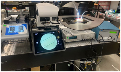
FIGURE 1. A view of experimental setup including syringe pump, microscope, function generator, and RF amplifier.
2.3 Neural Network Design
The Artificial Neural Networks (ANNs) capability in highly nonlinear data recognition in multivariate systems makes them an ideal technique for microfluidics design automation applications (Rizkin et al., 2019; Honrado et al., 2020; Lashkaripour et al., 2021). In most of the microfluidic devices, there are some dominating parameters (such as flowrates, voltage, geometrical features etc.) that significantly influence the performance of the micro devices; tuning these parameters for the desired application is one of the major challenges of the field. The prediction capability of the machine learning platforms makes them an ideal tool for eliminating trial and error in the design process. This technique could be easily applied for design automation of different types of active and passive microfluidics devices (such as micromixers, dielectrophoresis, and optical microseparators). In this paper, the feedforward backpropagation neural network based on Levenberg-Marquardt algorithm is proposed for the quality assessment of acoustofluidic devices. Levenberg-Marquardt is a supervised technique for properly tuning the neural network weights, which fine-tunes the weights according to the gradient of a loss function calculated in the previous epoch (i.e., iteration). This method is an adaptive function network that utilizes the Jacobian matrix and evaluates the network performance as the mean squared of the error. The MSE measure between the desired
where
where
where term
where
2.4 Multi-Objective Optimization
Combining neural networks with optimization algorithms can provide a robust optimization platform for microfluidic systems. The multi-objective heuristic optimization approaches have shown their superiority in tuning the operating parameters and design optimization of microfluidic devices (Talebjedi et al., 2021c). In this study, for identifying the optimum combination of the design factors for minimum reflection coefficient and quality factor, the trained neural network model was used in connection with NSGA-II multi-objective genetic algorithm. The GA first starts by generating an initial population of the chromosome, which are a possible solution for genetic algorithm optimization. The fitness function is used for determining the best chromosomes with highest survival ability and reproducibility. Here, the fitness function was created according to the developed ANN model. Individuals’ competition with their parents produces the offspring for next-generation creation, so that the superb individuals are retained, leading to a rise in the overall population evolution level. The newly generated population outperforms the previous population by continuing the process of selection, crossover and mutation on each generation (Talebjedi et al., 2020). Here, the Nondominated Sorting Genetic Algorithm (NSGA-II) is utilized for global optimization objectives of the reflection coefficient and quality factor as the algorithm is fast and avoids local optimal solution. The multi-objective optimization problems return the Pareto-optimal solution, showing a trade-off between objective functions subjected to defined constraints. The suggested solutions on the Pareto front are equally suitable and none of them have superiority over others. The decision-maker chooses between points according to the application to meet the required criteria. The flowchart of the ANN-GA algorithm is shown in Figure 2.
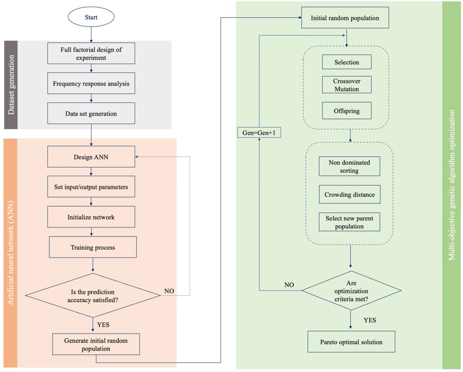
FIGURE 2. Flowchart of ANN-GA algorithm.
2.5 Governing Equations
The computation of harmonic acoustic pressure distribution was obtained by Helmholtz wave equation defined as follow:
where
where
where
3 Results and Discussion
3.1 Validation
In this study, the numerical analysis was performed using the finite element analysis (FEA) software package (COMSOL Multiphysics, version 5.6). The preliminary mesh dependency test was carried out to find the optimum grid size. The resonant frequency and reflection coefficient measures were the controlling parameters for monitoring the convergency test and validation. Four different mesh setups with 754,321, 1,256,798, 1,794,532 and 2,1457,68 grids were used for experiment number 108 simulation. This experiment’s resonant frequency and reflection coefficient are
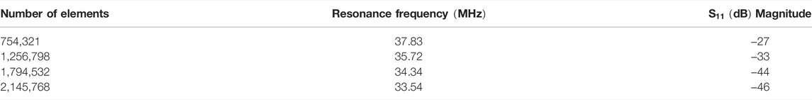
TABLE 1. Different meshing systems for the Grid-dependency test.
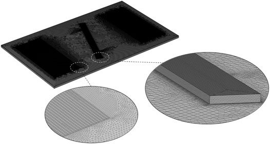
FIGURE 3. Numerical grids of a 3D acoustic actuator.
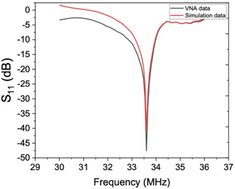
FIGURE 4. Comparison of the frequency response results from numerical simulation and experimental data for experiment number 108.
3.2 Frequency Response Prediction
Here we develop two multi-layer perceptron (MLP) neural networks for creating accurate prediction models of the resonator frequency response (reflection coefficient and Q-factor) according to different IDT geometry features. The dataset was obtained by laying out a full factorial design of experiment (DOE). Three main parameters, including length of the electrodes
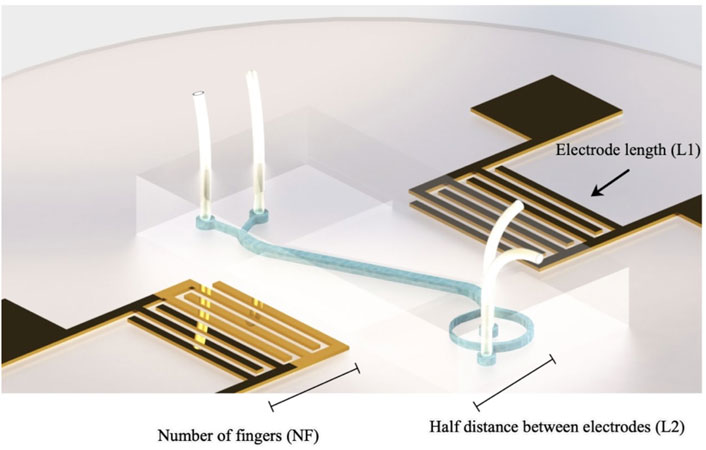
FIGURE 5. Schematic view of the acoustofluidic microseparator and IDT features.
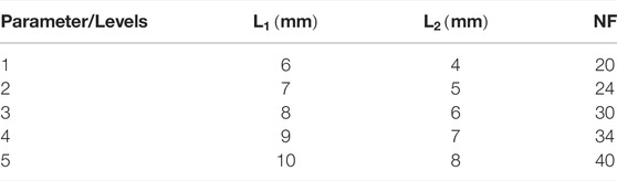
TABLE 2. Microseperator design parameters and levels.
Figure 6 demonstrates the coefficient of determination
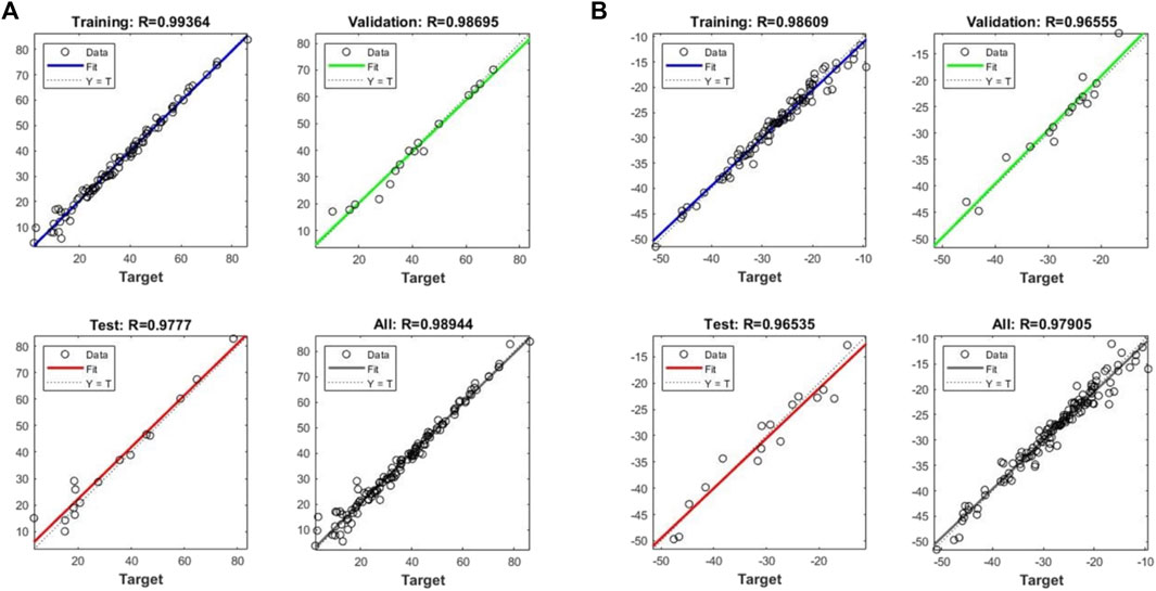
FIGURE 6. Measures of the R-squared for train, validation, and entire data for (A) Reflection coefficient and (B) Q-factor models.
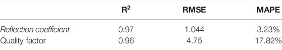
TABLE 3. The measures of the performance analysis of the prediction model.
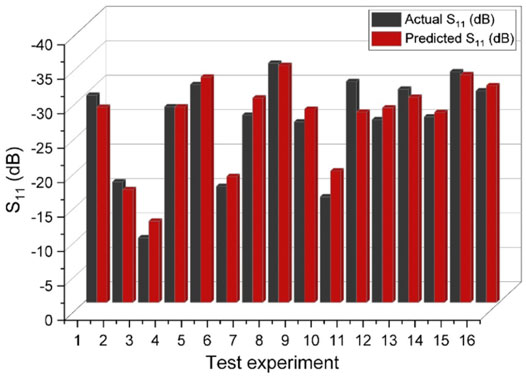
FIGURE 7. The comparison of actual and predicted reflection coefficient values for different experiments.
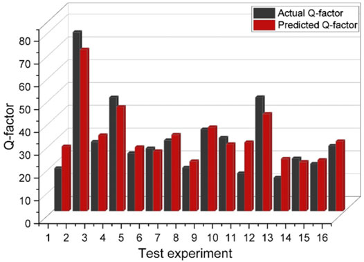
FIGURE 8. The comparison of actual and predicted Q-factor values for different experiments.
3.3 Multi-Objective Optimization of Artificial Neural Networks
To demonstrate the capability of the prediction models in delivering the best optimized user-specified performance in terms of reflection coefficient and Q-factor, we benefited from a heuristic multi-objective optimization approach. In this regard, we considered two ANNs as objective functions of the Genetic algorithm subjected to some constraints. In this study, the constraints were considered as the lower and upper bounds of the IDT features. A Pareto-optimal front was created with an optimized trade-off between the objectives (i.e., minimum reflection coefficient and Q-factor). As each point of the Pareto front is a globally optimal solution, non of the Pareto-optimal solutions have superiority over others for both objectives; thus, the solution’s choice depends on the performance that meets the designer’s need. Figure 9 demonstrates the Pareto front of two objective functions. To examine how multi-objective optimization aids in improving the performance of the acoustofluidic device in separating and confining the particles, we picked up a point on the Pareto front with reflection coefficient as
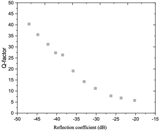
FIGURE 9. Pareto front of the reflection coefficient and Q-factor models.
3.4 Sensitivity Analysis
3.4.1 Reflection Coefficient
The range of reflection coefficient for different geometrical configurations was observed between
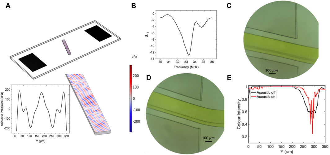
FIGURE 10. The results of the numerical and experimental studies corresponding to experiment number 36 with tilt angle 20°. (A) Contours of the acoustic pressure field distribution inside the fluidic domain. (B) The frequency response of the resonator. (C) The flow of
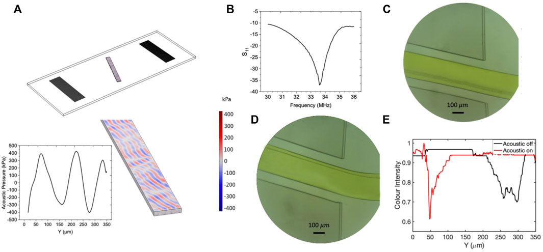
FIGURE 11. The results of the numerical and experimental studies corresponding to experiment number 90 with tilt angle 20°. (A) Contours of the acoustic pressure field distribution inside the fluidic domain. (B) The frequency response of the resonator. (C) The flow of
3.4.2 Quality Factor
The other key parameter strongly affecting the isolation efficiency is the bandwidth. Finding the exact value of the resonant frequency requires the VNA machine, which is very expensive and space-consuming. Moreover, sometimes the resonant frequency does not stay constant and shifts slightly during the experiment. For devices with narrow bandwidth, the minute shift in the resonant frequency causes a remarkable rise in return loss, while the wideband coverage means that the system can still operate with some degree of deviation from the resonant frequency without any considerable change in return loss. The elimination of using VNA machine for finding the resonant frequency and benefiting from simple equation
To investigate the role of bandwidth on separation efficiency, we conducted two experiments with high and low-quality factors. Experiment number 12 with quality factor 14 and experiment number 5 with quality number 78 were selected for numerical and experimental studies. The frequency response of these two experiments are represented in Figure 12. As Figure 12 reveals, both devices show similar reflection coefficient value about
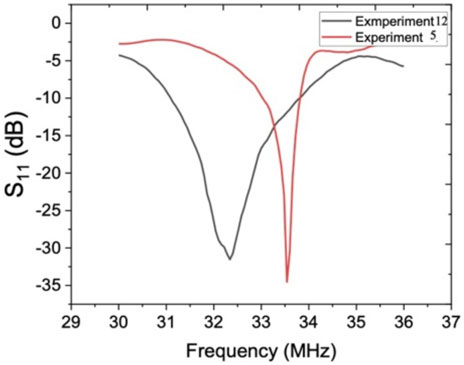
FIGURE 12. Frequency response of experiment numbers 12 and 5.
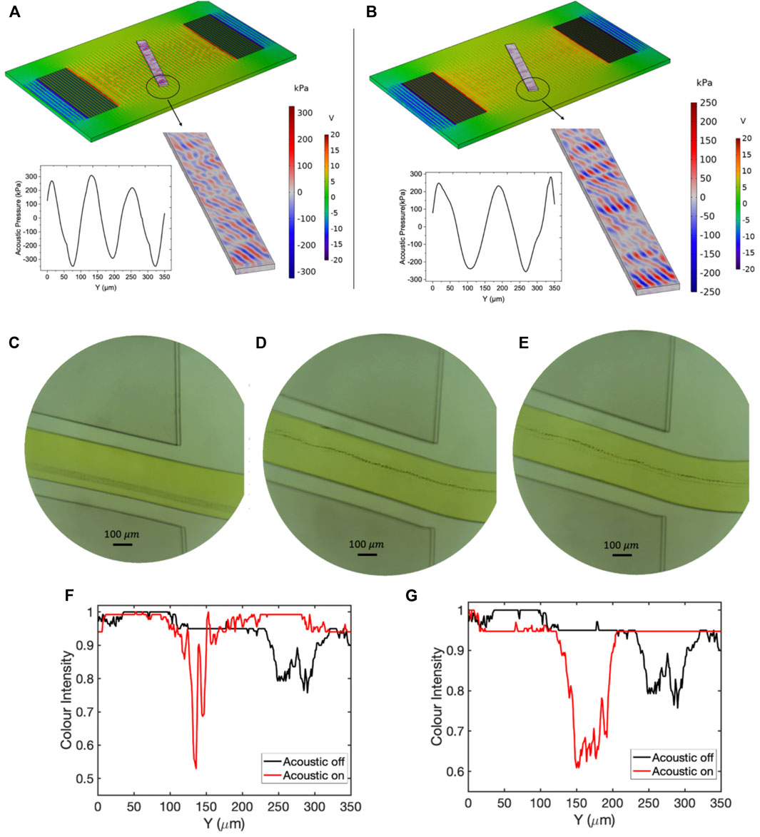
FIGURE 13. The results of pressure distribution and experimental tests for experiment number 12 with Q-factor 14 in resonant frequency and
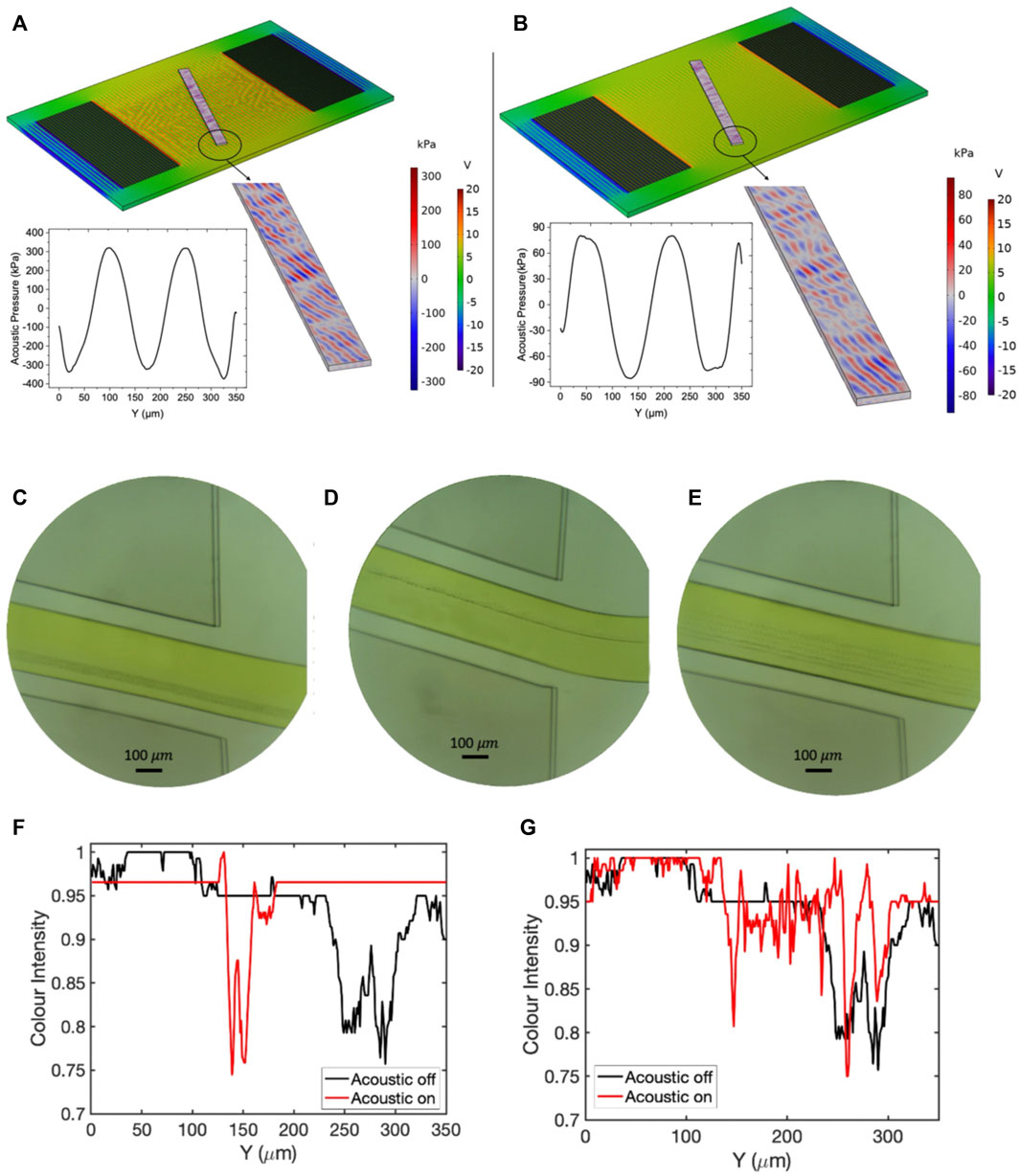
FIGURE 14. The results of pressure distribution and experimental tests for experiment number 5 with Q-factor 78 in resonant frequency and
4 Conclusion
A learning-based approach for optimizing an acoustic transducer by combining the ANN and MOGA was introduced for the first time. The developed ANNs revealed an equivalent accuracy to experimental test with
Data Availability Statement
The raw data supporting the conclusion of this article will be made available by the authors, without undue reservation.
Author Contributions
BT: Conceptualization, methodology, software, writing—original draft, formal analysis, writing—review and editing. Mohammadamin Heydari; Data acquisition, device fabrication, investigation. ET: Numerical simulation, conceptualization. NT: writing—review and editing. IL: Supervision, funding acquisition, writing—review and editing. MH: Supervision, funding acquisition, project administration, writing—review and editing.
Funding
This work was supported by the Eminence Fund from The University of British Columbia and the Discovery Grant (RGPIN-2017-04407) from the Natural Sciences and Engineering Research Council (NSERC) of Canada.
Conflict of Interest
The authors declare that the research was conducted in the absence of any commercial or financial relationships that could be construed as a potential conflict of interest.
Publisher’s Note
All claims expressed in this article are solely those of the authors and do not necessarily represent those of their affiliated organizations, or those of the publisher, the editors and the reviewers. Any product that may be evaluated in this article, or claim that may be made by its manufacturer, is not guaranteed or endorsed by the publisher.
Supplementary Material
The Supplementary Material for this article can be found online at: https://www.frontiersin.org/articles/10.3389/fbioe.2022.878398/full#supplementary-material
References
Ahmed, H., Destgeer, G., Park, J., Afzal, M., and Sung, H. J. (2018). Sheathless Focusing and Separation of Microparticles Using Tilted-Angle Traveling Surface Acoustic Waves. Anal. Chem. 90 (14), 8546–8552. doi:10.1021/acs.analchem.8b01593
Antfolk, M., and Laurell, T. (2017). Continuous Flow Microfluidic Separation and Processing of Rare Cells and Bioparticles Found in Blood - A Review. Analytica Chim. Acta 965, 9–35. doi:10.1016/j.aca.2017.02.017
Carugo, D., Octon, T., Messaoudi, W., Fisher, A. L., Carboni, M., Harris, N. R., et al. (2014). A Thin-Reflector Microfluidic Resonator for Continuous-Flow Concentration of Microorganisms: A New Approach to Water Quality Analysis Using Acoustofluidics. Lab. Chip 14 (19), 3830–3842. doi:10.1039/c4lc00577e
Chen, L., and Wang, Y. (2021). Dependence of Modified Butterworth Van-Dyke Model Parameters and Magnetoimpedance on Dc Magnetic Field for Magnetoelectric Composites. Materials 14 (16), 4730. doi:10.3390/ma14164730
Dalili, A., Samiei, E., and Hoorfar, M. (2019). A Review of Sorting, Separation and Isolation of Cells and Microbeads for Biomedical Applications: Microfluidic Approaches. Analyst 144 (1), 87–113. doi:10.1039/C8AN01061G
Fu, Y. Q., Luo, J. K., Nguyen, N. T., Walton, A. J., Flewitt, A. J., Zu, X. T., et al. (2017). Advances in Piezoelectric Thin Films for Acoustic Biosensors, Acoustofluidics and Lab-On-Chip Applications. Prog. Mater. Sci. 89, 31–91. doi:10.1016/j.pmatsci.2017.04.006
Honrado, C., McGrath, J. S., Reale, R., Bisegna, P., Swami, N. S., and Caselli, F. (2020). A Neural Network Approach for Real-Time Particle/cell Characterization in Microfluidic Impedance Cytometry. Anal. Bioanal. Chem. 412 (16), 3835–3845. doi:10.1007/s00216-020-02497-9
Lashkaripour, A., Rodriguez, C., Mehdipour, N., Mardian, R., McIntyre, D., Ortiz, L., et al. (2021). Machine Learning Enables Design Automation of Microfluidic Flow-Focusing Droplet Generation. Nat. Commun. 12 (1). doi:10.1038/s41467-020-20284-z
Lee, K., Shao, H., Weissleder, R., and Lee, H. (2015). Acoustic Purification of Extracellular Microvesicles. ACS Nano 9 (3), 2321–2327. doi:10.1021/nn506538f
Leibacher, I., Reichert, P., and Dual, J. (2015). Microfluidic Droplet Handling by Bulk Acoustic Wave (BAW) Acoustophoresis. Lab. Chip 15 (13), 2896–2905. doi:10.1039/C5LC00083A
Li, B.-W., Wei, K., Liu, Q.-Q., Sun, X.-G., Su, N., Li, W.-M., et al. (2021). Enhanced Separation Efficiency and Purity of Circulating Tumor Cells Based on the Combined Effects of Double Sheath Fluids and Inertial Focusing. Front. Bioeng. Biotechnol. 9 (10), 1–15. doi:10.3389/fbioe.2021.750444
Li, S., Ma, F., Bachman, H., Cameron, C. E., Zeng, X., and Huang, T. J. (2017). Acoustofluidic Bacteria Separation. J. Micromech. Microeng. 27 (1), 015031. doi:10.1088/1361-6439/27/1/015031
Liang, L.-G., Kong, M.-Q., Zhou, S., Sheng, Y.-F., Wang, P., Yu, T., et al. (2017). An Integrated Double-Filtration Microfluidic Device for Isolation, Enrichment and Quantification of Urinary Extracellular Vesicles for Detection of Bladder Cancer. Sci. Rep. 7, 1–10. doi:10.1038/srep46224
Liu, C., Ding, B., Xue, C., Tian, Y., Hu, G., and Sun, J. (2016). Sheathless Focusing and Separation of Diverse Nanoparticles in Viscoelastic Solutions with Minimized Shear Thinning. Anal. Chem. 88 (24), 12547–12553. doi:10.1021/acs.analchem.6b04564
Liu, S. C., Yoo, P. B., Garg, N., Lee, A. P., and Rasheed, S. (2021). A Microfluidic Device for Blood Plasma Separation and Fluorescence Detection of Biomarkers Using Acoustic Microstreaming. Sensors Actuators A: Phys. 317, 112482. doi:10.1016/j.sna.2020.112482
Ramshani, Z., Zhang, C., Richards, K., Chen, L., Xu, G., Stiles, B. L., et al. (2019). Extracellular Vesicle microRNA Quantification from Plasma Using an Integrated Microfluidic Device. Commun. Biol. 2 (1), 189. doi:10.1038/s42003-019-0435-1
Rizkin, B. A., Popovich, K., and Hartman, R. L. (2019). Artificial Neural Network Control of Thermoelectrically-Cooled Microfluidics Using Computer Vision Based on IR Thermography. Comput. Chem. Eng. 121, 584–593. doi:10.1016/j.compchemeng.2018.11.016
Taatizadeh, E., Dalili, A., Rellstab-Sánchez, P. I., Tahmooressi, H., Ravishankara, A., Tasnim, N., et al. (2021). Micron-sized Particle Separation with Standing Surface Acoustic Wave-Experimental and Numerical Approaches. Ultrason. Sonochem. 76, 105651. doi:10.1016/j.ultsonch.2021.105651
Talebjedi, B., Ghazi, M., Tasnim, N., Janfaza, S., and Hoorfar, M. (2021). Performance Optimization of a Novel Passive T-Shaped Micromixer with Deformable Baffles. Chem. Eng. Process. - Process Intensification 163 (3), 108369. doi:10.1016/j.cep.2021.108369
Talebjedi, B., Khosravi, A., Laukkanen, T., Holmberg, H., Vakkilainen, E., and Syri, S. (2020). Energy Modeling of a Refiner in Thermo-Mechanical Pulping Process Using ANFIS Method. Energies 13 (19), 5113. doi:10.3390/en13195113
Talebjedi, B., Laukkanen, T., Holmberg, H., Vakkilainen, E., and Syri, S. (2021). Energy Simulation and Variable Analysis of Refining Process in Thermo-Mechanical Pulp Mill Using Machine Learning Approach. Math. Comp. Model. Dynamical Syst. 27 (1), 562–585. doi:10.1080/13873954.2021.1990967
Talebjedi, B., Tasnim, N., Hoorfar, M., Mastromonaco, G. F., and De Almeida Monteiro Melo Ferraz, M. (2021). Exploiting Microfluidics for Extracellular Vesicle Isolation and Characterization: Potential Use for Standardized Embryo Quality Assessment. Front. Vet. Sci. 7, 1139. doi:10.3389/fvets.2020.620809
Turan, B., Masuda, T., Lei, W., Noor, A. M., Horio, K., Saito, T. I., et al. (2018). A Pillar-Based Microfluidic Chip for T-Cells and B-Cells Isolation and Detection with Machine Learning Algorithm. Robomech J. 5 (1). doi:10.1186/s40648-018-0124-8
Wang, H., Liu, Z., Shin, D. M., Chen, Z. G., Cho, Y., Kim, Y.-J., et al. (2019). A Continuous-Flow Acoustofluidic Cytometer for Single-Cell Mechanotyping. Lab. Chip 19 (3), 387–393. doi:10.1039/c8lc00711j
Wang, T., Green, R., Guldiken, R., Wang, J., Mohapatra, S., and Mohapatra, S. S. (2019). Finite Element Analysis for Surface Acoustic Wave Device Characteristic Properties and Sensitivity. Sensors 19 (8), 1749. doi:10.3390/s19081749
Wang, Z., Li, F., Rufo, J., Chen, C., Yang, S., Li, L., et al. (2020). Acoustofluidic Salivary Exosome Isolation: A Liquid Biopsy Compatible Approach for Human Papillomavirus-Associated Oropharyngeal Cancer Detection. J. Mol. Diagn. 22 (no. 1), 50–59. doi:10.1016/j.jmoldx.2019.08.004
Wunsch, B. H., Smith, J. T., Gifford, S. M., Wang, C., Brink, M., Bruce, R. L., et al. (2016). Nanoscale Lateral Displacement Arrays for the Separation of Exosomes and Colloids Down to 20 Nm. Nat. Nanotech 11 (8), 936–940. doi:10.1038/nnano.2016.134
Xie, Y., Mao, Z., Bachman, H., Li, P., Zhang, P., Ren, L., et al. (2020). Acoustic Cell Separation Based on Density and Mechanical Properties. J. Biomech. Eng. 142 (3), 1–9. doi:10.1115/1.4046180
Yang, J., Hooper, W. C., Phillips, D. J., Tondella, M. L., and Talkington, D. F. (2002). Centrifugation of Human Lung Epithelial Carcinoma A549 Cells Up-Regulates Interleukin-1beta Gene Expression. Clin. Diagn. Lab. Immunol. 9 (5), 1142–1143. doi:10.1128/CDLI.9.5.1142-1143.2002
Yeo, J. C., Kenry, , , Zhao, Z., Zhang, P., Wang, Z., and Lim, C. T. (2018). Label-free Extraction of Extracellular Vesicles Using Centrifugal Microfluidics. Biomicrofluidics 12 (2), 024103. doi:10.1063/1.5019983
Yiannacou, K., and Sariola, V. (2021). Controlled Manipulation and Active Sorting of Particles inside Microfluidic Chips Using Bulk Acoustic Waves and Machine Learning. Langmuir 37 (14), 4192–4199. doi:10.1021/acs.langmuir.1c00063
Zhang, P., He, M., and Zeng, Y. (2016). Ultrasensitive Microfluidic Analysis of Circulating Exosomes Using a Nanostructured Graphene Oxide/polydopamine Coating. Lab. Chip 16 (16), 3033–3042. doi:10.1039/c6lc00279j
Keywords: acoustofluidics, microfluidics, particle separation, artificial neural network, multi-objective optimization, pareto front
Citation: Talebjedi B, Heydari M, Taatizadeh E, Tasnim N, Li ITS and Hoorfar M (2022) Neural Network-Based Optimization of an Acousto Microfluidic System for Submicron Bioparticle Separation. Front. Bioeng. Biotechnol. 10:878398. doi: 10.3389/fbioe.2022.878398
Received: 18 February 2022; Accepted: 01 April 2022;
Published: 19 April 2022.
Edited by:
Petra Paie, Consiglio Nazionale delle Ricerche, ItalyCopyright © 2022 Talebjedi, Heydari, Taatizadeh, Tasnim, Li and Hoorfar. This is an open-access article distributed under the terms of the Creative Commons Attribution License (CC BY). The use, distribution or reproduction in other forums is permitted, provided the original author(s) and the copyright owner(s) are credited and that the original publication in this journal is cited, in accordance with accepted academic practice. No use, distribution or reproduction is permitted which does not comply with these terms.
*Correspondence: Mina Hoorfar, bWluYS5ob29yZmFyQHViYy5jYQ==