 Pedram Azizi
 Christoph Drobek1
 Silvia Budday
 Hermann Seitz
- 1Chair of Microfluidics, Faculty of Mechanical Engineering and Marine Technology, University of Rostock, Rostock, Germany
- 2Department of Mechanical Engineering, Institute of Applied Mechanics, Friedrich-Alexander-University Erlangen-Nürnberg, Erlangen, Germany
3D-structured hydrogel scaffolds are frequently used in tissue engineering applications as they can provide a supportive and biocompatible environment for the growth and regeneration of new tissue. Hydrogel scaffolds seeded with human mesenchymal stem cells (MSCs) can be mechanically stimulated in bioreactors to promote the formation of cartilage or bone tissue. Although in vitro and in vivo experiments are necessary to understand the biological response of cells and tissues to mechanical stimulation, in silico methods are cost-effective and powerful approaches that can support these experimental investigations. In this study, we simulated the fluid-structure interaction (FSI) to predict cell differentiation on the entire surface of a 3D-structured hydrogel scaffold seeded with cells due to dynamic compressive load stimulation. The computational FSI model made it possible to simultaneously investigate the influence of both mechanical deformation and flow of the culture medium on the cells on the scaffold surface during stimulation. The transient one-way FSI model thus opens up significantly more possibilities for predicting cell differentiation in mechanically stimulated scaffolds than previous static microscale computational approaches used in mechanobiology. In a first parameter study, the impact of the amplitude of a sinusoidal compression ranging from 1% to 10% on the phenotype of cells seeded on a porous hydrogel scaffold was analyzed. The simulation results show that the number of cells differentiating into bone tissue gradually decreases with increasing compression amplitude, while differentiation into cartilage cells initially multiplied with increasing compression amplitude in the range of 2% up to 7% and then decreased. Fibrous cell differentiation was predicted from a compression of 5% and increased moderately up to a compression of 10%. At high compression amplitudes of 9% and 10%, negligible areas on the scaffold surface experienced high stimuli where no cell differentiation could occur. In summary, this study shows that simulation of the FSI system is a versatile approach in computational mechanobiology that can be used to study the effects of, for example, different scaffold designs and stimulation parameters on cell differentiation in mechanically stimulated 3D-structured scaffolds.
1 Introduction
Hydrogels are polymer networks that can hold large amounts of water, and their mechanical properties can be adjusted to match many native tissues (Blache et al., 2022). Their material characteristics have made them proper choices for producing scaffolds in tissue engineering. These hydrogel-based scaffolds form an artificial microenvironment that can mimic many properties of the native extracellular matrix (ECM) and respond to different stimuli similarly to the native ECM (Neves et al., 2020). Many cell activities in their microenvironment depend on mechanical stimulation. For example, organ formation, tissue regeneration, repair, and aging depend highly on the dynamic interaction between cells and their microenvironment (Iskratsch et al., 2014). The application of 3D hydrogel scaffolds in cartilage and bone tissue engineering for studying the repair processes both in vitro and in vivo is of great scientific interest (Song et al., 2020). The 3D structured scaffolds, which are modeled using computer-aided design (CAD), can be fabricated using additive manufacturing (AM) strategies. One printing technique within AM that has been utilized to create 3D structured scaffolds is the direct ink writing (DIW) method (Saadi et al., 2022). For example, DIW-printed scaffolds can be applied to repair and regenerate load-bearing bone defects (Fu et al., 2011; Deliormanli and Rahaman, 2012). The printed bio-scaffolds’ mechanical behavior is in good agreement with human bone and cartilage tissues, and they have outstanding biocompatibility (Saadi et al., 2022). Hydrogel scaffolds are designed to mimic biological structures, and since cells can be seeded into them homogeneously, they are great options for creating in vitro cell culture systems (Naveena et al., 2012). Bioreactors allow to create an environment for these cell cultures, which imitates the in vivo physiological conditions (Schulz and Bader, 2007). As an example of bioreactors’ application in tissue engineering, Meinert et al., 2017 created a novel bioreactor system to develop human cartilage neotissue promoted by mechanical stimulation in a controlled and monitored manner. Cell proliferation and differentiation processes inside the bioreactors are dependent on applied mechanical stimuli and, as a result, on the reconstructed cells’ microenvironment (Castro et al., 2020). The biological response of tissue and cells to mechanical stimulation is the subject of mechanobiology (Giorgi et al., 2016).
The use of in silico models in mechanobiology is a cost-effective method to broaden knowledge in tissue engineering and reduce the number of in vitro experiments. Moreover, computational mechanobiology is a powerful method to assess biological processes and provides valuable information on biophysical parameters that cannot be measured experimentally (Dolan et al., 2018). The finite element (FE) analysis and computational fluid dynamic (CFD) are the two main numerical methods applied in this field of study. The FE analysis has been performed to investigate the relationship between structural (porosity, pore size, pore architecture, etc.) and mechanical properties (stress, strain, elastic modulus, etc.) of regular and irregular scaffolds (Olivares et al., 2009; Gomez et al., 2016; Du et al., 2019; Arjunan et al., 2020). The CFD approach has been widely used to study scaffolds’ permeability and wall shear stress (WSS) caused by fluid flow inside the scaffolds (Ali and Sen, 2018; Ouyang et al., 2019; Zhianmanesh et al., 2019; Mahammod et al., 2020). In addition to CFD simulation of unseeded scaffolds, researchers have also utilized CFD to understand the influence of cell (or tissue) growth on the flow field surrounding the scaffold (Lesman et al., 2010; Guyot et al., 2015). However, mechanobiology is a multiscale and multiphysics problem. Hence, the fluid-structure interaction (FSI) simulation provides new opportunities for researchers to study mechanobiology (Giorgi et al., 2016).
Simulation of an FSI system can simultaneously analyze fluid and solid environments for tissue engineering applications. Tresoldi et al. (2017) conducted a two-dimensional axial-symmetric FSI simulation to evaluate mechanical stimulations acting on a scaffold system for vascular cells. They showed that FSI-computed working pressure and circumferential strains were in good agreement with the experimental values. In a recent work by Zhao et al. (2020) a multiscale FSI model was applied to evaluate the mechanical stimulation received by the cells in a perfusion bioreactor before (at day 0) and after tissue growth (at day 28). Their numerical investigation employed the FSI simulation at the microscale level (cell/ECM) at 12 locations in the scaffold, and the flow was modeled steady-state in the perfusion bioreactor. In the study of Ferroni et al. (2016) a 3D FSI micro-scale model of a porous scaffold was created to evaluate the WSS inside it. From a comparison of the computed WSS between the simple laminar flow model and FSI, they concluded that implementing an FSI model is mandatory to accurately predict the interaction between media and the scaffold during mechanical stimulation. The influence of structural parameters of regular scaffolds on mechanical stimulation and mass transport was studied by Malve et al. (2018) using the FSI simulation. Their investigation reported that cells should be seeded in the central regions of the scaffold to avoid high WSS values near the outer edges of the scaffold and to have uniform nutrient distribution within it. Fu et al. (2021) used a two-way method to simulate the FSI system and investigate the effect of the structural design of the scaffolds on the WSS on the surface of the deformable cells. In the computational study by Zhao et al. (2015) osteoblasts were modeled as cells attached to the scaffold or as cells bridged within the scaffold pores. Their FSI results found that fluid flow stimulated bridged cells more significantly than attached cells. In their computational analysis, similar to the study by Zhao et al. (2020) FSI simulation was employed in the microscale level for stimulation by perfusion under steady-state fluid flow.
Numerical methods are also utilized to predict the cell phenotype in tissue differentiation. Computational models of tissue differentiation consider mechanical loads that produce biophysical stimuli, including stress, strain, fluid flow, pressure, electrical potential, etc.(Prendergast et al., 2010,356). Prendergast et al. (1997) presented a mechano-regulationtheory in which mesenchymal stem cells’ fate is regulated by the combined biophysical stimuli(S) of tissue shear strain and fluid flow. Researchers used this theory to predict tissue phenotypes, especially with poroelastic FE analysis (Huiskes et al., 1997; Lacroix et al., 2002; Isaksson et al., 2006; Byrne et al., 2007; Milan et al., 2010; Koh et al., 2019; Perier-Metz et al., 2020). However, some other studies have adopted the mentioned mechano-regulation concept to alternative numerical methods (Olivares et al., 2009; Sandino and Lacroix, 2011; Hendrikson et al., 2017; Castro and Lacroix, 2018). Castro and Lacroix (2018) modeled the scaffold and its local environment as poro-hyperelastic materials. Their computational study evaluated the mechanical stimuli for different geometry models (CAD- and μCT-derived models) under unconfined and confined compression using nine FE models. Two separate FE simulations were performed in the investigation by Sandino and Lacroix (2011). In one FE analysis, the octahedral shear strain (OSS) was computed as a result of compressive strain, and in the other FE model, steady-state perfusion fluid flow inside the scaffold was simulated to obtain the WSS. From the computed values of WSS and OSS, the mechano-regulatory stimulus (S) was computed at each element, and consequently, the differentiated tissues were predicted within the scaffold. Olivares et al. (2009) calculated the initial stimuli sensed by the cells by analyzing two different solid and fluid phases. They computed OSS using a linear elastic FE analysis of the scaffold and WSS using a steady-state CFD simulation within the pore volume to obtain the mechanical stimuli. Hendrikson et al. (2017) also studied the influence of compressive loads on cell differentiation of different scaffold architectures by employing a combination of FE and CFD simulations. Their study concentrated on the influence of the additive manufactured scaffold architecture on the stress and strain distribution and, thus, on the calculated mechanical stimuli.
In this study we present a transient one-way FSI model that considers mechanical and fluid dynamic influences on cells cultivated on a porous 3D scaffold. To the authors’ best knowledge, this is the first FSI-based model that can predict the phenotype of cells on the entire surface of dynamically stimulated scaffolds. In contrast to previous multiscale approaches that considered only a limited number of locations in the scaffold in a steady-state simulation (Zhao et al., 2015; Zhao et al., 2020), we simulated the complete scaffold transiently at the macroscale level to study the spatially resolved stimulation effects over the entire scaffold surface. This allows the numerical prediction of cell differentiation on the surface of a porous hydrogel scaffold as a result of mechanical compression stimulation. In a first parameter study, we used this model to analyze the differentiation of the cells on the surface of a 3D-structured hydrogel scaffold surface as a function of the load amplitude.
2 Materials and methods
2.1 Geometry
A stimulation bioreactor was considered in which a small piston could move vertically to compress a scaffold inside a 12-well microwell plate. Accordingly, the diameter and height of the well were 21 and 8.5 mm, respectively, as shown in Figure 1. The top surface of the well is open so that the piston can move freely vertically to compress the scaffold.
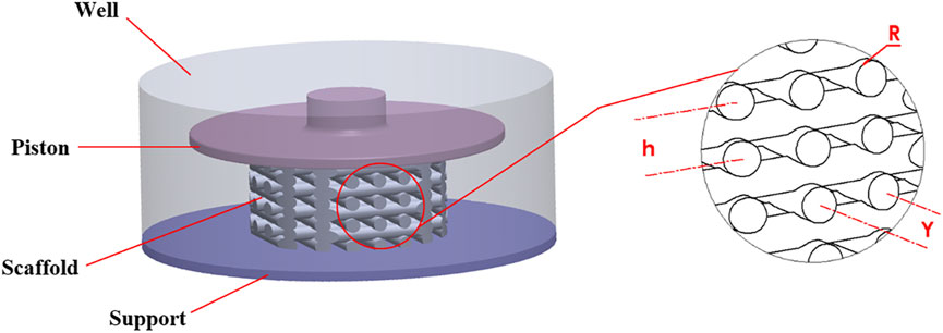
FIGURE 1. Geometry of the well, scaffold and piston (left side), scaffold details (right side).
The scaffold dimensions were chosen so that the scaffold could both be manufactured using DIW and fit into the 12-well microwell plate. The scaffold had a regular structure and was modeled with the CAD tool SOLIDWORKS (Dassault Systèmes SolidWorks Corporation, MA, United States). It had a height of 4.8 mm and a diameter of 10 mm. As shown in Figure 1, the geometrical parameters of the scaffold were defined as R = 0.35 mm (strand radius), Y = 1.4 mm (horizontal span), and h = 1.12 mm (vertical distance between two adjacent strands).
2.2 Mesh generation
To generate the mesh and run the simulations ANSYS 2020R2 (ANSYS Inc., PA, United States) was utilized. The entire structural and fluid domains were spatially discretized using ANSYS Meshing. During the mesh generation, particular attention was paid to the scaffold surface, as this region needed to be properly refined for the calculation of the mechano-regulatory forces. The mesh configurations of the FE and CFD models are shown in Figures 2A, B, respectively, where the areas with refined mesh can be recognized. Scaffold and piston were discretized using tetrahedral (Tet10) elements in the solid model while hexahedral elements (Hex20) were applied for the support (Figure 2A). The whole fluid domain was meshed using tetrahedral (Tet10) elements (Figure 2B). It can be seen from Figure 2C that the conformal meshing technique is applied between solid and fluid environments on the scaffold surface. As a result, FE and CFD nodes matched at each element on the scaffold surface, and calculating structural and fluidic properties at the same node was possible.
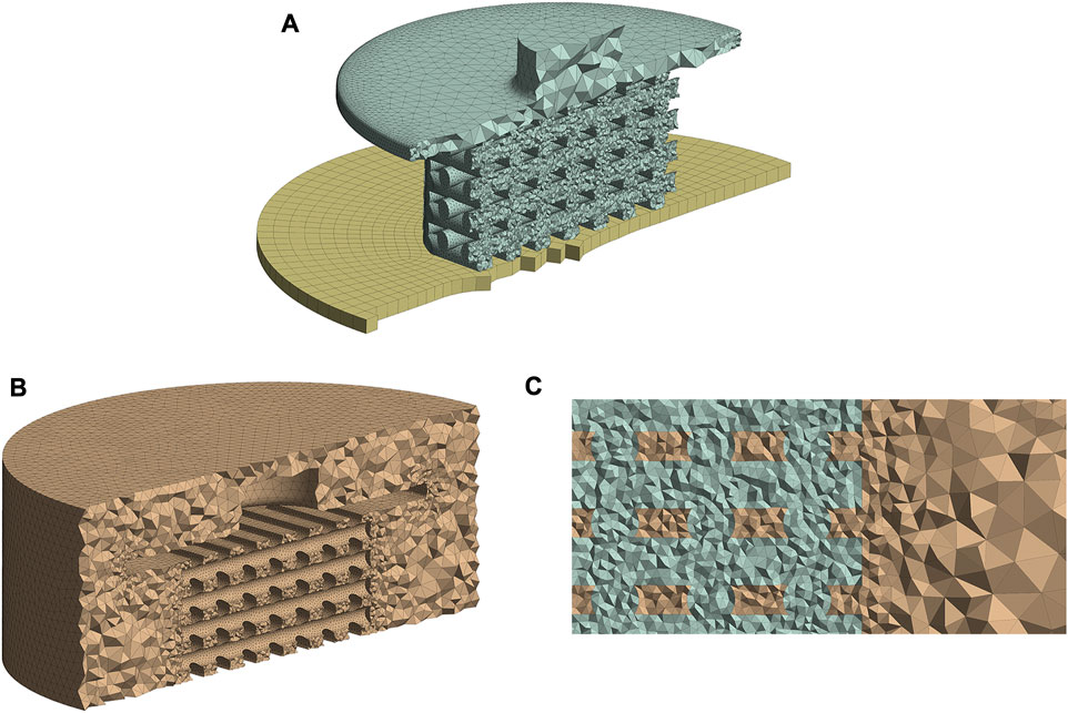
FIGURE 2. Mesh structures of the FE (A) and CFD (B) models. Conformal meshing between fluid and solid zones was applied to the scaffold surface (C). All figure panels show section views of the numerical models.
A mesh independence study was performed to understand the influence of element numbers on the simulation results (Supplementary Table S1 in Supplementary Material). Considering the mesh size influence on cell phenotypes prediction (Supplementary Table S2 in Supplementary Material), a mesh configuration of 7,80,094 FE model elements and 1,216,293 CFD elements (Medium mesh from Supplementary Table S1 in Supplementary Material) had good agreement with the finest studied mesh. Therefore, this mesh setup was chosen for all simulations in our study.
2.3 FE model
The boundary conditions were determined in ANSYS Transient Structural to perform FE analysis. Figure 3A shows the three parts of the FE model: piston, scaffold, and support. The piston can move vertically (y direction) to compress the scaffold, while the support is fixed and cannot move or rotate in any direction. Both piston and support have frictional contact with the scaffold, and the vertical displacement of the piston was defined sinusoidally with a frequency of 1Hz, as shown in Figure 3B. Sinusoidal displacement with a frequency of 1 Hz was successfully applied in the study by Pioletti et al. (2003) to experimentally stimulate osteoblast-like cells. Moreover, previous studies also investigated mechanical stimulation in tissue-engineered cartilage, applying a dynamic compression load at 1 Hz (Mauck et al., 2000; Kisiday et al., 2004), because this frequency mimics the pace of the human gait (Salinas et al., 2018). We performed ten simulations with ten different compression amplitudes to study the influence of compression amplitude on cell differentiation. These values were 1%–10% of the original scaffold height with an interval of 1%. Previous in vitro studies of dynamic compressive loading on tissue-engineered cartilage confirms that amplitudes up to 10% improves biomechanical and biochemical properties (El-Ayoubi et al., 2011; Nebelung et al., 2012; Shahin and Doran, 2012; Salinas et al., 2018). Furthermore, Michalopoulos et al. (2012) found that seeded human mesenchymal stem cells (MSCs) differentiate toward osteogenesis on scaffolds stimulated with a cyclic compressive strain of 10%.
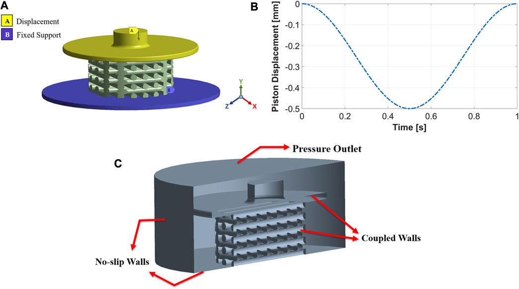
FIGURE 3. The FE model includes a movable piston on the top, support at the bottom, and a scaffold between the two (A). Implemented compression load during one cycle for an amplitude of 10% (B). Boundary conditions of the CFD model (C).
A pure oxidized alginate-gelatin (ADA-GEL) hydrogel was chosen as the scaffold material. Based on compression-tension experiments (Distler et al., 2021), we have previously shown that the hyperelastic response of pure ADA-GEL can be well captured by the one-term Ogden model (Ogden, 1972). We used the ANSYS hyperelastic material model in this study. To determine hyperelastic materials, a strain-energy density function (usually denoted as
where W is the strain energy potential,
The set of material parameters was identified based on compression-tension experiments by Distler et al. (2021). We defined them for N = 1 as μ1 = −5.8 kPa and α1 = −1.3 on the assumption of a fully incompressible material behavior (d1 = 0). For fully incompressible materials, mixed u-P formulation had to be applied by ANSYS to get the solutions (Ansys® Academic Research Mechanical, 2020b).
The material properties did not change during the loading cycle because the viscoelastic behavior of the scaffold was not considered. Therefore, only one loading cycle was simulated.
2.4 CFD model
Fluid flow inside the mechanically stimulated 3D-structured scaffold was modeled using ANSYS Fluent, which is based on the finite volume method (FVM). The fluid zones which received displacements from the structural model, i.e., piston and scaffold walls, were treated with a dynamic mesh approach. This approach combined smoothing based on the diffusion method with the remeshing method for all deforming zones. These parts of the fluid domain were coupled to the FE model and meshed as fluid-solid interface zones. No-slip wall boundary conditions were applied to the well’s bottom and cylindrical walls, as seen in Figure 3C. The fluid domain’s top surface was considered a pressure-outlet boundary with atmospheric pressure (Figure 3C).
The culture medium was modeled as a Newtonian, incompressible fluid with a density of 1,000 kg/
2.5 FSI system
A 3D fluid-structure interaction (FSI) transient one-way model was used to analyze fluidic and mechanical properties of the regular scaffold. The FSI system was modeled based on a co-simulation strategy, in which a converged solution from the FE model was obtained at each coupling iteration. These results defined the CFD model’s new boundary conditions, i.e., deformation from the FE model induced fluid flow in the CFD model. The two physics solvers were coupled using ANSYS System Coupling. The co-simulation process was repeated at each simulation time step until the cycle of the compressive stimulation reached the end (i.e., after 1 s simulation time). Due to the physics of this FSI problem, a one-way FSI approach was sufficient instead of a two-way approach because the solid motion induced the fluid flow. Nevertheless, the fluid flow did not significantly affect the solid deformation. All simulations were performed on a Windows workstation with a 24-core processor and 256 GB RAM. Subsequently, the results of the FSI simulations were read with a MATLAB R2021a (Math Works Inc., MA, United States) script, and cell phenotypes were predicted using a mechano-regulatory algorithm described in chapter 2.6.
The accuracy of the results in the transient FSI model depends not just on the mesh size but also on choosing the appropriate time step size. In our study, the CFD model’s dynamic mesh method decides the time step size. According to ANSYS Fluent User’s Guide, Release 2020 R2, the relative mesh motion should not exceed the smallest element. This condition can be written as:
where
Piston speed, mesh size, and compression amplitude are the three parameters influencing choosing time step size. The piston movement influences
Taking the criteria of Eq. 2 into account, three different time step sizes were considered to assess their influence on the simulation results for a compression of 10%: large (0.004 s), medium (0.002 s), and small (0.001 s) time step sizes. Comparing the average and maximum values of OSS and WSS indicated that the three chosen time intervals result in almost similar structural and fluidic behavior. Moreover, the relative errors in cell phenotype prediction (bone, cartilage, and fibrous cells) of the large time step size compared with the small time step size were calculated at three sample simulation times. The relative error was less than 2% in all examined simulation times. As a result, the large time step size (0.004 s) was applied to perform the simulations with a lower computational cost.
2.6 Evaluation of mechanical stimuli
A German orthopedic surgeon, Friedrich Pauwels, related the biophysical stimuli to MSCs’ fate (Pauwels, 1960; Prendergast et al., 2010, 360–361). He hypothesized that deformation leads to the differentiation of MSCs into fibrous tissue, while hydrostatic compression gives rise to the differentiation of MSCs into cartilage; a mixture of these stimuli leads to fibrocartilage tissue (Prendergast, 2004, 119–120; Prendergast et al., 2010, 360–361). Based on the ideas of Pauwels, Prendergast et al. (1997) developed a mechano-regulation theory that proposed that the fate of MSCs is controlled by strain and fluid flow. A modified version of this theory (Olivares et al., 2009; Sandino and Lacroix, 2011; Hendrikson et al., 2017) which substitutes fluid velocity with wall shear stress (WSS), has been implemented in the current study to compute the mechano-regulatory stimulus as:
where S is the stimulus, OSS is the octahedral shear strain, WSS is wall shear stress, and constants a and b are equal to 0.0375 and 10 mPa (Olivares et al., 2009; Sandino and Lacroix, 2011; Hendrikson et al., 2017). The tissue phenotype was predicted by computing the stimulus (S) and its classification according to the modified mechano-regulation theory (Olivares et al., 2009; Sandino and Lacroix, 2011; Hendrikson et al., 2017): If
The OSS was computed from the FE model as follows:
where
where
As mentioned in Section 2.3, the material model of the scaffold is not time-dependent because the viscoelastic properties of the scaffold are not considered. Therefore, the computed OSS values do not differ during successive loading cycles.
The WSS on the scaffold surfaces were calculated from the laminar CFD model as follows:
where
The two output parameters, OSS and WSS, had to be computed at the same element nodes to calculate S. Therefore, as mentioned in Section 2.2, a conformal meshing technique was applied to match the element nodes of the FE and CFD models. The FE and CFD results were matched at the same nodes using a MATLAB script; thus, the stimuli could be calculated. Since we developed a transient FSI model with dynamic loading conditions, different configurations of cell phenotypes on the scaffold surface could be calculated at each position of the moving piston (i.e., at each simulation time point). To predict tissue phenotypes after a single complete loading cycle, the following calculations were performed using MATLAB: First, the average value of stimuli (
3 Results
In the FSI simulation of a dynamic mechanical stimulation process, the prediction of the cell phenotype on the scaffold surface changes at each simulation time point (piston position), as explained in Section 2.6. Figures 4A–C show the results used to determine the simulation time points at which the cell phenotypes were predicted. Figure 4A shows that
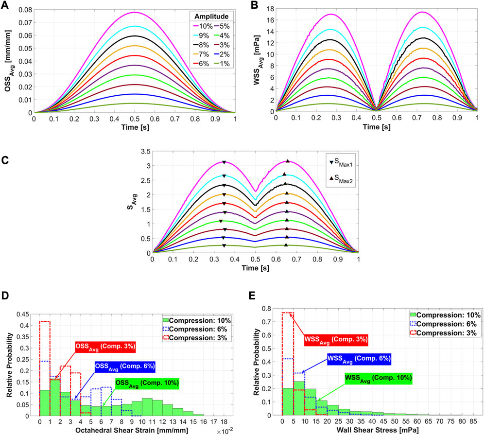
FIGURE 4. Average octahedral shear strain (A) and area-weighted averaged wall shear stress (B) during the loading cycle for different compression amplitudes. The average values of stimuli (
Figure 5 shows both the fluid flow field and mechanical deformation of the scaffold during stimulation with a compression amplitude of 10% at three different simulation time points. The piston displacement curve as well as the three normalized curves of
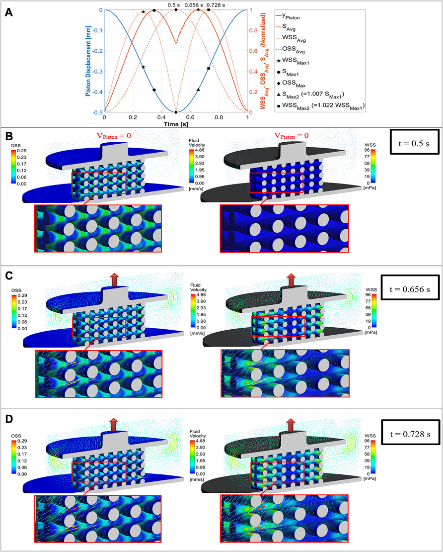
FIGURE 5. Mechano-regulatory stimuli (solid red curve) based on average values of WSS (dotted curve) and OSS (dashed curve) plotted versus simulation time along with the displacement curve of the piston (blue curve) for one loading cycle (A), OSS distribution on the scaffold surface (left) compared with WSS distribution (right) for a compression amplitude of 10% at three different simulation time points (piston positions), when the maximum value of OSS (B), the maximum value of
The cell distributions on the scaffold surface for the three exemplary compression amplitudes 3%, 6%, and 10% are shown in Figure 6 at
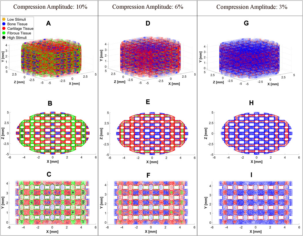
FIGURE 6. Cell differentiation on the scaffold surface at a compression amplitude of 10% (A), 6% (D), and 3% (G). Top view (XZ Plane) of cell differentiation on the scaffold surface at a compression amplitude of 10% (B), 6% (E), and 3% (H). Side view (XY Plane) of cell differentiation on the scaffold surface at a compression amplitude of 10% (C), 6% (F), and 3% (I). The cell differentiation was predicted at
An overview of the cell differentiation for the compression range between [1% 10%] with an interval of 1% is depicted in Figure 7. It can be seen from this graph that with increasing compression amplitude, bone cell differentiation decreased. Cartilage cell differentiation rose from 2% to 7% compression and decreased slightly thereafter. From 5% to 10% compression, a fibrous cell phenotype was predicted to develop on larger areas of the scaffold with increasing compression amplitude. At high compressions of 9%–10%, the stimuli were too high in very small areas of the scaffold to lead to any cell differentiation.
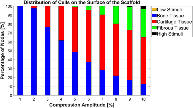
FIGURE 7. Percentage distribution of cell phenotypes on the scaffold surface for 10 different compression amplitudes.
4 Discussion
In this study, a transient one-way FSI model was developed to analyze the influence of mechanical stimulation on cell differentiation. After selecting a reliable simulation setup (e.g., ensuring the independency of results from mesh size and simulation time step size), the influence of the sinusoidal compression loads on cell differentiation was studied. At low compressive loads, the bone cell phenotype was predominantly predicted, which is also confirmed by previous research (Byrne et al., 2007; Milan et al., 2010; Castro and Lacroix, 2018; Horner et al., 2018). Increasing compression amplitudes resulted in differentiation of stem cells into cartilage and fibrous tissues, whereas the percentage of differentiated bone cells decreased.
The location of maximum strain was determined at the intersections of the strands, which was also found in previous studies (Hendrikson et al., 2017; Malve et al., 2018). It has been assumed that cell death may occur at OSS values higher than 0.225 (Olivares et al., 2009; Sandino and Lacroix, 2011). Our results report that the average values of OSS for all compression loads are below this value (Figure 4A). Considering the histogram for the highest compression amplitude of 10%, it can be seen that no region on the scaffold has an OSS higher than 0.225 (Figure 4D). Despite this fact, cell apoptosis occurs in a small area of the scaffold surface (Figure 7). This demonstrates that cell differentiation depends not only on the OSS, but also on the WSS caused by the fluid flow and both effects have to be considered simultaneously.
The acceptable WSS range for cell differentiation was assumed to be [0.01 60] mPa (Sandino and Lacroix, 2011), while a peak shear stress of 57 mPa was associated with cell apoptosis (Porter et al., 2005). Our analysis of
Although in vitro and in vivo experiments have shown that dynamic compression promotes MSCs’ differentiation, the mechanism which explains the influence of compression stimulus on MSCs has not yet been wholly understood (Sun et al., 2022). Thus, selecting the appropriate simulation time point when the mechanical stimulation could determine the cell phenotype was one of the challenges in predicting tissue phenotype using the dynamic FSI model. Since the mechanical stimulation depends on both the WSS induced by fluid flow and the OSS due to the deformation of the scaffold, it was impossible to determine the maximum stimulus at each node during simulation. Each scaffold area experienced variable fluid shear stress stimuli and compression strain stimuli. The maximum values of these two stimuli types did not occur at the same time point. Other researchers also reported that certain scaffold areas are affected by maximum values of just one of these stimuli (Sandino et al., 2008; Malve et al., 2018). Therefore, averaged values of these parameters were investigated during one loading cycle. However, the maximum
The literature describes that the magnitude of compression is a possible parameter to control MSC differentiation (Sun et al., 2022). Our study also demonstrated that the compression amplitude is a crucial factor for cell differentiation. For instance, when the compression amplitude was increased from 5% to 10%, the portion of bone cell phenotype on the scaffold surface decreased from 48.64% to 12.53%. Conversely, the fibrous cell phenotype showed an increase from 1.12% to 31.62% while no significant change in the proportion of cartilage cell phenotype was observed (Figure 7). Prediction of cell differentiation on a scaffold as a function of compression amplitude was previously investigated by Hendrikson et al. (2017). Their computed cell differentiation results, based on the combination of OSS and WSS for scaffolds with orthogonal strands (0/90 scaffold architecture), show qualitatively almost the same trend as the results in Figure 7. However, their computational analysis did not consider compression-induced fluid flow. In addition, their modeled scaffolds differed from the scaffolds in the current study, leading to quantitatively different results.
The combination of FE analysis and FVM within a transient FSI model allows us to obtain valuable data from both the fluid and solid domains. However, the accuracy of the model in predicting cell differentiation depends on the meshing strategy and the number of elements, since in FVM, the results are computed at element centers. In contrast, in our FE model, they are determined at element nodes and also at internal nodes for elements with Lagrangian multiplier (Ansys® Academic Research Mechanical, 2020b). Therefore, transferring the FVM results from element centers to the element nodes is necessary to calculate stimuli, but this requires interpolating these results. A reduction of the element size is required to reduce the differences between nodal and central values of the CFD model. This leads to the use of a fine mesh for both the FE and CFD models, with the chosen conformal meshing approach being computationally expensive.
Although a one-way FSI model was applied in this study, fluid flow in other bioreactor configurations, such as perfusion bioreactors, may cause deformation of the scaffold, and this resulting displacement may also affect fluid motion. For such problems, two-way FSI simulations should be considered.
Since the material properties of the model did not change over time, the analysis of cell differentiation in a single loading cycle, as performed in this study, is sufficient. Due to the constant material properties, the prediction of the cell phenotypes does not change with the presented model when the simulation is performed for additional loading cycles. In other words, the model just considered the homeostatic state of the scaffold, and the intermediate situations that influence cell differentiation were neglected. In future analyses, the changes in material characteristics and scaffold morphology due to neo-tissue formation should be updated over the loading cycles during long-term stimulations. Hence, real in vitro changes in scaffold properties can be considered, and the model will make better predictions. Moreover, the hyperplastic material used cannot mimic all the properties of hydrogels. Therefore, the application of time-dependent parameters of hyper-viscoelastic material models can also improve the predictability of cell differentiation (Weizel et al., 2023). This will particularly be of interest as the viscoelastic properties, i.e., the stress relaxation behavior, has been shown to control cell behavior (Chaudhuri et al., 2015; Chaudhuri et al., 2016). Finally, even though our study predicts cell differentiation based on an experimentally validated mechano-regulation theory (Prendergast et al., 1997), a compression bioreactor could be utilized to validate the numerical results of our model.
5 Conclusion
In this study, a transient one-way FSI model for predicting cell differentiation on the surface of a mechanically stimulated porous hydrogel scaffold was presented. This model considers both stimulation due to mechanical deformation of the scaffold and due to compression-induced fluid flow during dynamic compressive stimulation. The presented model thus goes beyond previous FSI studies in the field of computational mechanobiology, which were mainly dealing with perfusion flows and steady-state-flow models. Stimulation due to structural strain and fluid shear stress stimuli were calculated simultaneously. It was shown that the amplitude of the compression load is a decisive factor for the control of cell differentiation. The results showed good agreement with previous studies and highlighted the applicability of the model in computational mechanobiology. This model can be used to not only analyze the influence of load amplitude but also of other stimulation parameters such as frequency, scaffold structure, and material properties on cell differentiation in early stages of cell cultivation. Consequently, the model can be used to optimize scaffold designs and stimulation protocols. Future studies should consider the change in material properties and tissue morphology that occur during long-term stimulation to improve the predictability of the model. For this purpose, the model parameters must be adjusted in simulations over several loading cycles. The FSI simulation is a powerful approach that can help to reduce in vitro and in vivo experiments and lower costs. In the field of mechanobiology, the presented approach can be applied in numerous other studies in the future to predict cell differentiation in similar tissue engineering problems based on mechanical stimulation.
Data availability statement
The original contributions presented in the study are included in the article/Supplementary Material, further inquiries can be directed to the corresponding author.
Author contributions
PA, HS, and CD conceptualized the study. PA created the model (except material modelling) and performed the simulations, analyzed and interpreted the computational results. HS acquired funding. SB modeled the hydrogel material properties based on experimental data. HS and CD substantially contributed to the interpretation of the simulation results. PA wrote the original draft. HS, CD, and SB contributed to manuscript writing and formatting. All authors contributed to the article and approved the submitted version.
Funding
This study is funded by the Deutsche Forschungsgemeinschaft (DFG, German Research Foundation) -SFB 1270/1; 2 -299150580 and INST 264/166-1 FUGG.
Acknowledgments
We thank Dr. Andy L. Olivares of Pompeu Fabra University for his valuable comments on the creation of the model.
Conflict of interest
The authors declare that the research was conducted in the absence of any commercial or financial relationships that could be construed as a potential conflict of interest.
Publisher’s note
All claims expressed in this article are solely those of the authors and do not necessarily represent those of their affiliated organizations, or those of the publisher, the editors and the reviewers. Any product that may be evaluated in this article, or claim that may be made by its manufacturer, is not guaranteed or endorsed by the publisher.
Supplementary material
The Supplementary Material for this article can be found online at: https://www.frontiersin.org/articles/10.3389/fbioe.2023.1249867/full#supplementary-material
References
Ali, D., and Sen, S. (2018). Permeability and fluid flow-induced wall shear stress of bone tissue scaffolds: computational fluid dynamic analysis using newtonian and non-newtonian blood flow models. Comput. Biol. Med. 99, 201–208. doi:10.1016/j.compbiomed.2018.06.017
Ansys® Academic Research Fluent, (2020). Release 2020 R2, help system, ANSYS fluent user’s Guide. Canonsburg, Pennsylvania, United States: ANSYS, Inc.
Ansys® Academic Research Mechanical, (2020a). Release 2020 R2, help system, mechanical APDL theory reference. Canonsburg, Pennsylvania, United States: ANSYS, Inc.
Ansys® Academic Research Mechanical, (2020b). Release 2020 R2, help system, mechanical APDL element reference. Canonsburg, Pennsylvania, United States: ANSYS, Inc.
Arjunan, A., Demetriou, M., Baroutaji, A., and Wang, C. (2020). Mechanical performance of highly permeable laser melted Ti6Al4V bone scaffolds. J. Mech. Behav. Biomed. Mater. 102, 103517. doi:10.1016/j.jmbbm.2019.103517
Blache, U., Ford, E. M., Ha, B., Rijns, L., Chaudhuri, O., Dankers, P. Y., et al. (2022). Engineered hydrogels for mechanobiology. Nat. Rev. Methods Prim. 2 (1), 98–22. doi:10.1038/s43586-022-00179-7
Byrne, D. P., Lacroix, D., Planell, J. A., Kelly, D. J., and Prendergast, P. J. (2007). Simulation of tissue differentiation in a scaffold as a function of porosity, young's modulus and dissolution rate: application of mechanobiological models in tissue engineering. Biomaterials 28 (36), 5544–5554. doi:10.1016/j.biomaterials.2007.09.003
Castro, A. P. G., and Lacroix, D. (2018). Micromechanical study of the load transfer in a polycaprolactone–collagen hybrid scaffold when subjected to unconfined and confined compression. Biomechanics Model. Mechanobiol. 17 (2), 531–541. doi:10.1007/s10237-017-0976-5
Castro, N., Ribeiro, S., Fernandes, M. M., Ribeiro, C., Cardoso, V., Correia, V., et al. (2020). Physically active bioreactors for tissue engineering applications. Adv. Biosyst. 4 (10), 2000125. doi:10.1002/adbi.202000125
Chaudhuri, O., Gu, L., Darnell, M., Klumpers, D., Bencherif, S. A., Weaver, J. C., et al. (2015). Substrate stress relaxation regulates cell spreading. Nat. Commun. 6 (1), 6365. doi:10.1038/ncomms7365
Chaudhuri, O., Gu, L., Klumpers, D., Darnell, M., Bencherif, S. A., Weaver, J. C., et al. (2016). Hydrogels with tunable stress relaxation regulate stem cell fate and activity. Nat. Mater. 15 (3), 326–334. doi:10.1038/nmat4489
Deliormanlı, A. M., and Rahaman, M. N. (2012). Direct-write assembly of silicate and borate bioactive glass scaffolds for bone repair. J. Eur. Ceram. Soc. 32 (14), 3637–3646. doi:10.1016/j.jeurceramsoc.2012.05.005
Distler, T., Kretzschmar, L., Schneidereit, D., Girardo, S., Goswami, R., Friedrich, O., et al. (2021). Mechanical properties of cell-and microgel bead-laden oxidized alginate-gelatin hydrogels. Biomaterials Sci. 9 (8), 3051–3068. doi:10.1039/D0BM02117B
Dolan, E. B., Verbruggen, S. W., and Rolfe, R. A. (2018). “Techniques for studying mechanobiology,” in Mechanobiology in health and disease (Cambridge, Massachusetts, United States: Academic Press), 1–53. doi:10.1016/B978-0-12-812952-4.00001-5
Du, Y., Liang, H., Xie, D., Mao, N., Zhao, J., Tian, Z., et al. (2019). Finite element analysis of mechanical behavior, permeability of irregular porous scaffolds and lattice-based porous scaffolds. Mater. Res. Express 6 (10), 105407. doi:10.1088/2053-1591/ab3ac1
El-Ayoubi, R., DeGrandpré, C., DiRaddo, R., Yousefi, A. M., and Lavigne, P. (2011). Design and dynamic culture of 3D-scaffolds for cartilage tissue engineering. J. biomaterials Appl. 25 (5), 429–444. doi:10.1177/0885328209355332
Ferroni, M., Giusti, S., Nascimento, D., Silva, A., Boschetti, F., and Ahluwalia, A. (2016). Modeling the fluid-dynamics and oxygen consumption in a porous scaffold stimulated by cyclic squeeze pressure. Med. Eng. Phys. 38 (8), 725–732. doi:10.1016/j.medengphy.2016.04.016
Fu, M., Wang, F., and Lin, G. (2021). Design and research of bone repair scaffold based on two-way fluid-structure interaction. Comput. Methods Programs Biomed. 204, 106055. doi:10.1016/j.cmpb.2021.106055
Fu, Q., Saiz, E., and Tomsia, A. P. (2011). Direct ink writing of highly porous and strong glass scaffolds for load-bearing bone defects repair and regeneration. Acta biomater. 7 (10), 3547–3554. doi:10.1016/j.actbio.2011.06.030
Giorgi, M., Verbruggen, S. W., and Lacroix, D. (2016). In silico bone mechanobiology: modeling a multifaceted biological system. Wiley Interdiscip. Rev. Syst. Biol. Med. 8 (6), 485–505. doi:10.1002/wsbm.1356
Gómez, S., Vlad, M. D., López, J., and Fernández, E. (2016). Design and properties of 3D scaffolds for bone tissue engineering. Acta biomater. 42, 341–350. doi:10.1016/j.actbio.2016.06.032
Guyot, Y., Luyten, F. P., Schrooten, J., Papantoniou, I., and Geris, L. (2015). A three-dimensional computational fluid dynamics model of shear stress distribution during neotissue growth in a perfusion bioreactor. Biotechnol. Bioeng. 112 (12), 2591–2600. doi:10.1002/bit.25672
Hendrikson, W. J., Deegan, A. J., Yang, Y., Van Blitterswijk, C. A., Verdonschot, N., Moroni, L., et al. (2017). Influence of additive manufactured scaffold architecture on the distribution of surface strains and fluid flow shear stresses and expected osteochondral cell differentiation. Front. Bioeng. Biotechnol. 5, 6. doi:10.3389/fbioe.2017.00006
Horner, C. B., Hirota, K., Liu, J., Maldonado, M., Hyle Park, B., and Nam, J. (2018). Magnitude-dependent and inversely-related osteogenic/chondrogenic differentiation of human mesenchymal stem cells under dynamic compressive strain. J. tissue Eng. Regen. Med. 12 (2), e637–e647. doi:10.1002/term.2332
Huiskes, R., Driel, W. V., Prendergast, P. J., and Søballe, K. (1997). A biomechanical regulatory model for periprosthetic fibrous-tissue differentiation. J. Mater. Sci. Mater. Med. 8 (12), 785–788. doi:10.1023/a:1018520914512
Isaksson, H., Wilson, W., van Donkelaar, C. C., Huiskes, R., and Ito, K. (2006). Comparison of biophysical stimuli for mechano-regulation of tissue differentiation during fracture healing. J. biomechanics 39 (8), 1507–1516. doi:10.1016/j.jbiomech.2005.01.037
Iskratsch, T., Wolfenson, H., and Sheetz, M. P. (2014). Appreciating force and shape—The rise of mechanotransduction in cell biology. Nat. Rev. Mol. Cell Biol. 15 (12), 825–833. doi:10.1038/nrm3903
Kisiday, J. D., Jin, M., DiMicco, M. A., Kurz, B., and Grodzinsky, A. J. (2004). Effects of dynamic compressive loading on chondrocyte biosynthesis in self-assembling peptide scaffolds. J. biomechanics 37 (5), 595–604. doi:10.1016/j.jbiomech.2003.10.005
Koh, Y. G., Lee, J. A., Kim, Y. S., Lee, H. Y., Kim, H. J., and Kang, K. T. (2019). Optimal mechanical properties of a scaffold for cartilage regeneration using finite element analysis. J. tissue Eng. 10, 204173141983213. doi:10.1177/2041731419832133
Lesman, A., Blinder, Y., and Levenberg, S. (2010). Modeling of flow-induced shear stress applied on 3D cellular scaffolds: implications for vascular tissue engineering. Biotechnol. Bioeng. 105 (3), 645–654. doi:10.1002/bit.22555
Lacroix, D., Prendergast, P. J., Li, G., and Marsh, D. (2002). Biomechanical model to simulate tissue differentiation and bone regeneration: application to fracture healing. Med. Biol. Eng. Comput. 40 (1), 14–21. doi:10.1007/BF02347690
Mahammod, B. P., Barua, E., Deb, P., Deoghare, A. B., and Pandey, K. M. (2020). Investigation of physico-mechanical behavior, permeability and wall shear stress of porous HA/PMMA composite bone scaffold. Arabian J. Sci. Eng. 45 (7), 5505–5515. doi:10.1007/s13369-020-04467-w
Malvè, M., Bergstrom, D. J., and Chen, X. B. (2018). Modeling the flow and mass transport in a mechanically stimulated parametric porous scaffold under fluid-structure interaction approach. Int. Commun. Heat Mass Transf. 96, 53–60. doi:10.1016/j.icheatmasstransfer.2018.05.014
Mauck, R. L., Soltz, M. A., Wang, C. C., Wong, D. D., Chao, P. H. G., Valhmu, W. B., et al. (2000). Functional tissue engineering of articular cartilage through dynamic loading of chondrocyte-seeded agarose gels. J. Biomech. Eng. 122 (3), 252–260. doi:10.1115/1.429656
Meinert, C., Schrobback, K., Hutmacher, D. W., and Klein, T. J. (2017). A novel bioreactor system for biaxial mechanical loading enhances the properties of tissue-engineered human cartilage. Sci. Rep. 7 (1), 16997. doi:10.1038/s41598-017-16523-x
Michalopoulos, E., Knight, R. L., Korossis, S., Kearney, J. N., Fisher, J., and Ingham, E. (2012). Development of methods for studying the differentiation of human mesenchymal stem cells under cyclic compressive strain. Tissue Eng. Part C. Methods 18 (4), 252–262. doi:10.1089/ten.tec.2011.0347
Milan, J. L., Planell, J. A., and Lacroix, D. (2010). Simulation of bone tissue formation within a porous scaffold under dynamic compression. Biomechanics Model. Mechanobiol. 9 (5), 583–596. doi:10.1007/s10237-010-0199-5
Naveena, N., Venugopal, J., Rajeswari, R., Sundarrajan, S., Sridhar, R., Shayanti, M., et al. (2012). Biomimetic composites and stem cells interaction for bone and cartilage tissue regeneration. J. Mater. Chem. 22 (12), 5239–5253. doi:10.1039/C1JM14401D
Nebelung, S., Gavenis, K., Lüring, C., Zhou, B., Mueller-Rath, R., Stoffel, M., et al. (2012). Simultaneous anabolic and catabolic responses of human chondrocytes seeded in collagen hydrogels to long-term continuous dynamic compression. Ann. Anatomy-Anatomischer Anzeiger 194 (4), 351–358. doi:10.1016/j.aanat.2011.12.008
Neves, S. C., Moroni, L., Barrias, C. C., and Granja, P. L. (2020). Leveling up hydrogels: hybrid systems in tissue engineering. Trends Biotechnol. 38 (3), 292–315.doi:10.1016/j.tibtech.2019.09.004
Ogden, R. W. (1972). Large deformation isotropic elasticity–on the correlation of theory and experiment for incompressible rubberlike solids. Proc. R. Soc. Lond. A. Math. Phys. Sci. 326 (1567), 565–584. doi:10.1098/rspa.1972.0026
Olivares, A. L., Marsal, È., Planell, J. A., and Lacroix, D. (2009). Finite element study of scaffold architecture design and culture conditions for tissue engineering. Biomaterials 30 (30), 6142–6149. doi:10.1016/j.biomaterials.2009.07.041
Ouyang, P., Dong, H., He, X., Cai, X., Wang, Y., Li, J., et al. (2019). Hydromechanical mechanism behind the effect of pore size of porous titanium scaffolds on osteoblast response and bone ingrowth. Mater. Des. 183, 108151. doi:10.1016/j.matdes.2019.108151
Pauwels, F. (1960). Eine neue Theorie über den Einfluß mechanischer Reize auf die Differenzierung der Stützgewebe. Z. für Anat. Entwicklungsgeschichte 121 (6), 478–515. doi:10.1007/bf00523401
Perier-Metz, C., Duda, G. N., and Checa, S. (2020). Mechano-biological computer model of scaffold-supported bone regeneration: effect of bone graft and scaffold structure on large bone defect tissue patterning. Front. Bioeng. Biotechnol. 8, 585799. doi:10.3389/fbioe.2020.585799
Pioletti, D. P., Müller, J., Rakotomanana, L. R., Corbeil, J., and Wild, E. (2003). Effect of micromechanical stimulations on osteoblasts: development of a device simulating the mechanical situation at the bone–implant interface. J. Biomechanics 36 (1), 131–135. doi:10.1016/S0021-9290(02)00301-9
Porter, B., Zauel, R., Stockman, H., Guldberg, R., and Fyhrie, D. (2005). 3-D computational modeling of media flow through scaffolds in a perfusion bioreactor. J. biomechanics 38 (3), 543–549. doi:10.1016/j.jbiomech.2004.04.011
Prendergast, P. J., Checa, S., and Lacroix, D. (2010). “Computational models of tissue differentiation,” in Computational modeling in biomechanics (Dordrecht, Netherlands: Springer), 353–372. doi:10.1007/978-90-481-3575-2_12
Prendergast, P. J. (2004). “Computational mechanobiology,” in Computational bioengineering: Current trends and applications. Editors M. Cerrolaza, M. Doblare, G. Martinez, and B. Calvo (London, UK: Imperial College Press), 117–133.
Prendergast, P. J., Huiskes, R., and Søballe, K. (1997). Biophysical stimuli on cells during tissue differentiation at implant interfaces. J. biomechanics 30 (6), 539–548. doi:10.1016/S0021-9290(96)00140-6
Song, J., Michas, C., Chen, C. S., White, A. E., and Grinstaff, M. W. (2020). From simple to architecturally complex hydrogel scaffolds for cell and tissue engineering applications: opportunities presented by two-photon polymerization. Adv. Healthc. Mater. 9 (1), 1901217. doi:10.1002/adhm.201901217
Saadi, M. A. S. R., Maguire, A., Pottackal, N. T., Thakur, M. S. H., Ikram, M. M., Hart, A. J., et al. (2022). Direct ink writing: A 3D printing technology for diverse materials. Adv. Mater. 34 (28), 2108855. doi:10.1002/adma.202108855
Salinas, E. Y., Hu, J. C., and Athanasiou, K. (2018). A guide for using mechanical stimulation to enhance tissue-engineered articular cartilage properties. Tissue Eng. Part B Rev. 24 (5), 345–358. doi:10.1089/ten.teb.2018.0006
Sandino, C., and Lacroix, D. (2011). A dynamical study of the mechanical stimuli and tissue differentiation within a CaP scaffold based on micro-CT finite element models. Biomechanics Model. Mechanobiol. 10 (4), 565–576. doi:10.1007/s10237-010-0256-0
Sandino, C., Planell, J. A., and Lacroix, D. (2008). A finite element study of mechanical stimuli in scaffolds for bone tissue engineering. J. biomechanics 41 (5), 1005–1014. doi:10.1016/j.jbiomech.2007.12.011
Schulz, R. M., and Bader, A. (2007). Cartilage tissue engineering and bioreactor systems for the cultivation and stimulation of chondrocytes. Eur. Biophysics J. 36, 539–568. doi:10.1007/s00249-007-0139-1
Shahin, K., and Doran, P. M. (2012). Tissue engineering of cartilage using a mechanobioreactor exerting simultaneous mechanical shear and compression to simulate the rolling action of articular joints. Biotechnol. Bioeng. 109 (4), 1060–1073. doi:10.1002/bit.24372
Sun, Y., Wan, B., Wang, R., Zhang, B., Luo, P., Wang, D., et al. (2022). Mechanical stimulation on mesenchymal stem cells and surrounding microenvironments in bone regeneration: regulations and applications. Front. Cell Dev. Biol. 10, 808303. doi:10.3389/fcell.2022.808303
Tresoldi, C., Bianchi, E., Pellegata, A. F., Dubini, G., and Mantero, S. (2017). Estimation of the physiological mechanical conditioning in vascular tissue engineering by a predictive fluid-structure interaction approach. Comput. methods Biomechanics Biomed. Eng. 20 (10), 1077–1088. doi:10.1080/10255842.2017.1332192
Weizel, A., Distler, T., Detsch, R., Boccaccini, A. R., Seitz, H., and Budday, S. (2023). Time-dependent hyper-viscoelastic parameter identification of human articular cartilage and substitute materials. J. Mech. Behav. Biomed. Mater. 138, 105618. doi:10.1016/j.jmbbm.2022.105618
Zhao, F., Van Rietbergen, B., Ito, K., and Hofmann, S. (2020). Fluid flow-induced cell stimulation in bone tissue engineering changes due to interstitial tissue formation in vitro. Int. J. Numer. methods Biomed. Eng. 36 (6), e3342. doi:10.1002/cnm.3342
Zhao, F., Vaughan, T. J., and Mcnamara, L. M. (2015). Multiscale fluid–structure interaction modelling to determine the mechanical stimulation of bone cells in a tissue engineered scaffold. Biomechanics Model. Mechanobiol. 14 (2), 231–243. doi:10.1007/s10237-014-0599-z
Keywords: cell differentiation, tissue engineering, fluid-solid interaction, computational fluid dynamic, finite element analysis, in silico
Citation: Azizi P, Drobek C, Budday S and Seitz H (2023) Simulating the mechanical stimulation of cells on a porous hydrogel scaffold using an FSI model to predict cell differentiation. Front. Bioeng. Biotechnol. 11:1249867. doi: 10.3389/fbioe.2023.1249867
Received: 29 June 2023; Accepted: 07 September 2023;
Published: 19 September 2023.
Edited by:
Ralph Müller, ETH Zürich, SwitzerlandCopyright © 2023 Azizi, Drobek, Budday and Seitz. This is an open-access article distributed under the terms of the Creative Commons Attribution License (CC BY). The use, distribution or reproduction in other forums is permitted, provided the original author(s) and the copyright owner(s) are credited and that the original publication in this journal is cited, in accordance with accepted academic practice. No use, distribution or reproduction is permitted which does not comply with these terms.
*Correspondence: Pedram Azizi, cGVkcmFtLmF6aXppQHVuaS1yb3N0b2NrLmRl