 Thomas J. Gilbert
 Zexiao Lin1
 Antonia F. de C. Hamilton
 Jamie A. Ward
- 1Engineering Department, University College London, London, United Kingdom
- 2Institute of Cognitive Neuroscience, University College London, London, United Kingdom
- 3Department of Computer Science, Goldsmiths, University of London, London, United Kingdom
This paper presents a novel method to synchronize multiple wireless inertial measurement unit sensors (IMU) using their onboard magnetometers. The basic method uses an external electromagnetic pulse to create a known event measured by the magnetometer of multiple IMUs and in turn uses this to synchronize the devices. An initial evaluation using four commercial IMUs reveals a maximum error of 40 ms per hour as limited by a 25 Hz sample rate. Building on this we introduce a novel method to improve synchronization beyond the limitations imposed by the sample rate and evaluate this in a further study using 8 IMUs. We show that a sequence of electromagnetic pulses, in total lasting <3-s, can reduce the maximum synchronization error to 8 ms (for 25 Hz sample rate, and accounting for the transient response time of the magnetic field generator). An advantage of this method is that it can be applied to several devices, either simultaneously or individually, without the need to remove them from the context in which they are being used. This makes the approach particularly suited to synchronizing multi-person on-body sensors while they are being worn.
1 Introduction
In the last decade there has been a huge growth in applications for IMU-enabled wearable and IOT devices. Applications stretch from the wider topics of human activity recognition (Bulling et al., 2014; Bian et al., 2022) and multi-sensor fusion (Gravina et al., 2017), to studies measuring social interaction and engagement in real-world settings (e.g., Gao et al., 2020; Sun et al., 2023). Many such applications require precise synchronization between separate IMU devices, an issue that is made all the more difficult over longer timescales. For example in Ward et al. (2018), recordings of multiple autistic children and actors performing together over several hours are analyzed to uncover fine-grained moments of motion synchrony. Similarly, Gao et al. (2020) records detailed physical and physiological data from students in class over a period of several weeks. In both of these examples, data is recorded offline on individual devices and then uploaded at the end of a session. To perform any time-series analysis or fine-grained fusion of such data, then precise synchronization between data sources is essential.
Most commercial IMUs include an on-board real-time clock (RTC). Unfortunately, typical RTCs tend to drift over time, such that over a long recording duration the clocks across multiple devices will vary wildly. This means that RTC-only based synchronization is not a viable option for longer experiments.
Efforts to overcome the synchronization problem can be grouped into three categories: network-based, event/gesture-based, or a combination. Much work has been done using Network Time Protocol (NTP; Li and Sinha, 2012; Wang et al., 2019; Yan et al., 2019; Raman et al., 2020) and Precision Time Protocol (PTP; Idrees et al., 2020) for time synchrony in IoT, however such protocols have been proven to be noisy with errors exceeding 1,800 ms or impractical for common mobile sensing task (Luo et al., 2017). Moreover, most commercial IMU devices do not have network options requiring external network chips to be included. One solution is to use sync events within the data itself, creating a common signal across different sensors and sensor types to facilitate temporal alignment. Kinetic events are most commonly used requiring the experimenter or participant to make a predefined movement, such as clapping or hitting the table (Plotz et al., 2012; Ward et al., 2017; Wang et al., 2019), or even tapping the ear (Hoelzemann et al., 2019). Bannach et al. (2009) show that synchronizing events can be collected from various sensors, including sound and light sensors. LED-sourced light has been used previously to update clock signals in IoT devices (Guo et al., 2016). ECG sensors have also been used to synchronize across wearable devices (Wolling et al., 2021a,b).
Electromagnetic fields have been previously used to synchronize wireless sensor networks (WSN). Rowe et al. (2009) developed an LC tank receiver circuit tuned to 60 Hz such that they can use the stochastic nature of the magnetic fields radiating from AC power lines to create a synchronizing signal. The method described achieves an average synchronization error of less than 1 ms. This requires the WSN to be near AC power lines which might limit the use in wearable applications (e.g., when outdoors). Another limitation pointed out by Rowe et al. (2009) is that the system temporarily fails when any objects get within proximity of the LC circuit creating a very strict synchronizing environment. Additionally, this method requires adding new hardware to commercial IMU devices.
In a recent work most similar to that presented here, Spilz and Munz (2023) demonstrate the use of inductors to create an electromagnetic event which is captured by magnetometers on Shimmer3 IMUs. They are able to achieve sub-sample period accuracy by looking at which transient responses have a sample present. This technique allows them to achieve a 2.6 ms offset error using 100 Hz magnetometers, requiring a synchronization time of 8 s. The method described is highly dependent on the IMUs being still relative to the inductors, therefore a synchronization box was developed to hold the IMUs in place. As the method described relies on a sample “hitting” a transient response, the chances of this happening decrease as the sample rate decreases, increasing the synchronization time proportionately to the decrease in sample frequency. Another limitation of the method is that all the IMUs must be synchronized at the same time meaning experiments are limited to the number of inductors in the synchronization box.
Most of the previous methods, particularly those requiring a kinetic event, can be disruptive often requiring the subjects to stop what they are doing to perform an action or even in some cases transfer their wearable sensors to holders. The method proposed by this paper minimizes these disruptions and replaces them with a wireless solution that requires no new hardware to be added to the commercial IMU devices.
The rest of the paper is structured as follows: The preliminary proof-of-concept experiment and results are discussed (as originally presented in Gilbert et al., 2022). We then introduce an extended method that improves synchronization beyond the limitations of the sample frequency and describe an experimental setup to evaluate this. Finally we present the results of these experiments and discuss the wider practical implications of the work.
2 Preliminary EMP study
A simple electromagnetic pulse generator (EMPG) was built by attaching an electromagnet to an Arduino UNO via a full h-bridge, as shown in Figure 1. This EMPG was configured to transmit a 4 period length pulse at 0.5 Hz. The electromagnet powered at 2 W has a magnetic field strength of 0.2μT at 11 cm. Below 0.2μT the magnetometer fails to measure the pulses giving an active range of 11 cm.
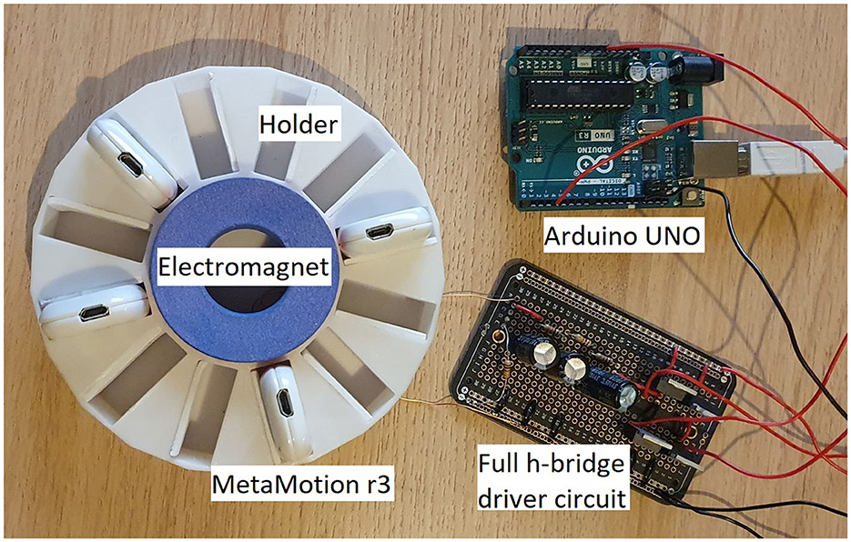
Figure 1. Experimental setup showing a simple 2 W EMPG circuit and holder with four MetaMotion IMUs.
Four MetaMotion R3 modules, from: Mbientlabs Inc, USA, were set up using an iPad. Each module was configured to logging mode. The magnetometer is activated to record at 25 Hz. Because the kinetic events will be used as an approximation of the “gold standard” (having been used in many previous works) against which the magnetic method will be evaluated, the accelerometer and gyroscopes are sampled at a higher rate of 100 Hz. The gyroscope was set to ±1600°/s. The accelerometer was set to ±16gs. The magnetometer's resolution is fixed at ±1300μT. The only physical requirement of the magnetometer method is that the sensors are within range of the EMPG. However, to ensure the efficacy of the kinetic method, the modules are placed in a holder so that they might be moved in synchrony together, as shown in Figure 1.
Two synchronizing events were generated at the start and end of the recording. A 4 period-length electromagnetic pulse (EMP) event was generated using the EMPG. A kinetic event as described in Ward et al. (2018) was then completed by swiftly lifting and slamming the holder on a table. The devices were then worn by the experimenter for sim1 h of arbitrary movement. Afterwards the devices were returned to the holder and the EMP and kinetic event repeated.
The raw 3-axis accelerometer, gyroscope, and magnetometer data of the devices were uploaded to an iPad and saved for processing in MATLAB. The orientation-invariant magnitude (Euclidean norm) of each sensor was calculated and mapped relative to epoch time. The timestamps for each device's data are aligned at upload time to the iPad. This means that data points taken toward the end of the recording have the most accurate timing, with those toward the start of the recording subject to larger timing errors. The data for the four devices are plotted in Figure 2 with the first kinetic and EMP events magnified.
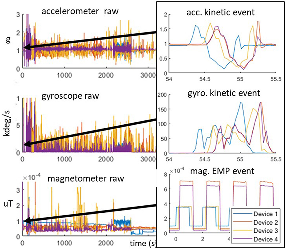
Figure 2. IMU magnitude data for four devices plotted against RTC time, highlighting “table slam” kinetic (accelerometer and gyroscope), and example of four equal-width EMP (magnetometer) pulses.
2.1 Preliminary results
The data is aligned manually using the kinetic (accelerometer) events, this is done in a similar way to that described by Bannach et al. (2009). Specifically, the data is plotted and aligned manually until they appear most correlated according to the “expert opinion” of the experimenter. To achieve this, an arbitrary device (device 1) is chosen as the reference to which all others are compared. The 1st kinetic event for each device is then aligned by translating their data. With the 1st events fixed, the data is then horizontally scaled (shortened or stretched) to align the 2nd events.
The RTC timing offsets for the two kinetic events (judged by expert opinion) are shown in Table 1. These show the offsets in ms of devices 2–4, relative to device 1. Note that after only 1 h of recording, there is a large RTC offset of 267 ms between devices 1 and 2.
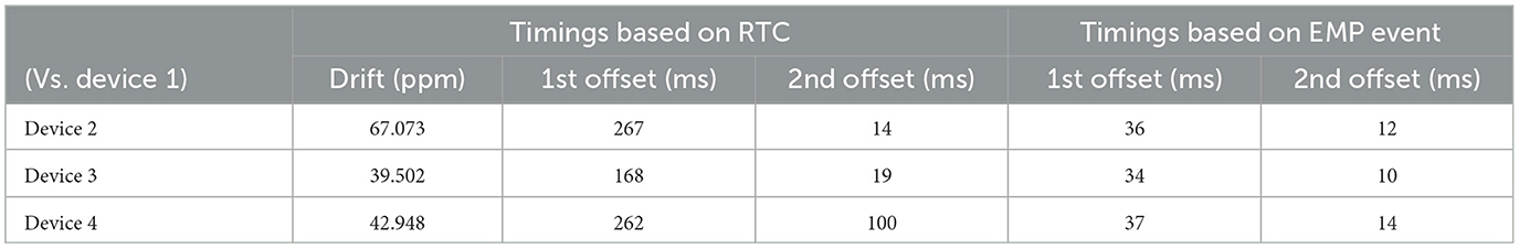
Table 1. Timing offsets between device 1 and the other IMU devices based on the RTC and EMP events for a 1 h recording.
Table 1 also shows the relative clock drift, in parts-per-million (ppm), of each device's RTC. Drift is calculated using , where Dd is the difference in offsets between each event, and D1 is the duration between the 1st and 2nd events for device 1. Refer to Figure 3 for a visual representation of the offsets and drift described in this paper.
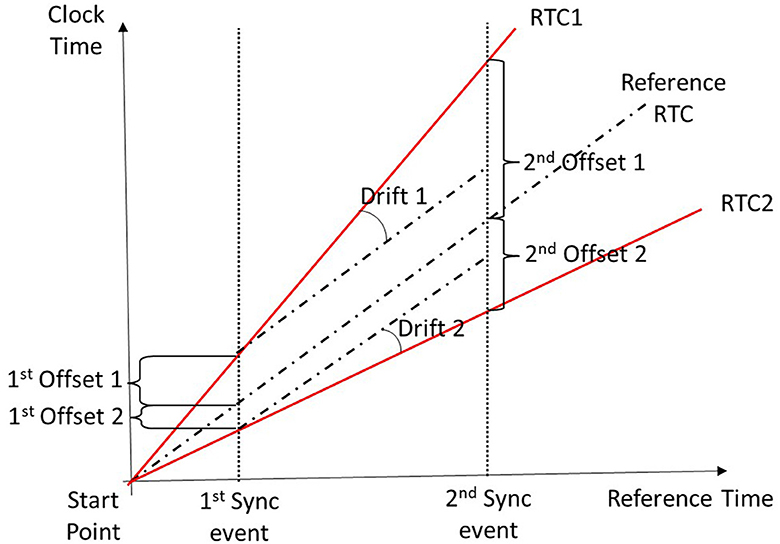
Figure 3. Timing diagram showing the offsets and drifts of 3 RTCs relative to one another.
The RTC crystal for each device has an accuracy of ~±40 ppm, so as the epoch time moves away from the RTC synchronization point the offset error will increase. The drift shown in Table 1 between devices 1 and 2 of 67 ppm indicates a large clock drift, but falling within the specified range (<40+40 = 80ppm for two devices).
To evaluate the EMP method, Devices 2–4 are re-aligned to device 1 by manually translating and scaling their data using the first rising edges of the 1st and 2nd EMP events. The difference between these EMP alignments and those of the kinetic events are shown in the rightmost columns of Table 1. A detailed plot of the events for the accelerometer and magnetometer before and after the EMP synchronization process are shown in Figure 4.
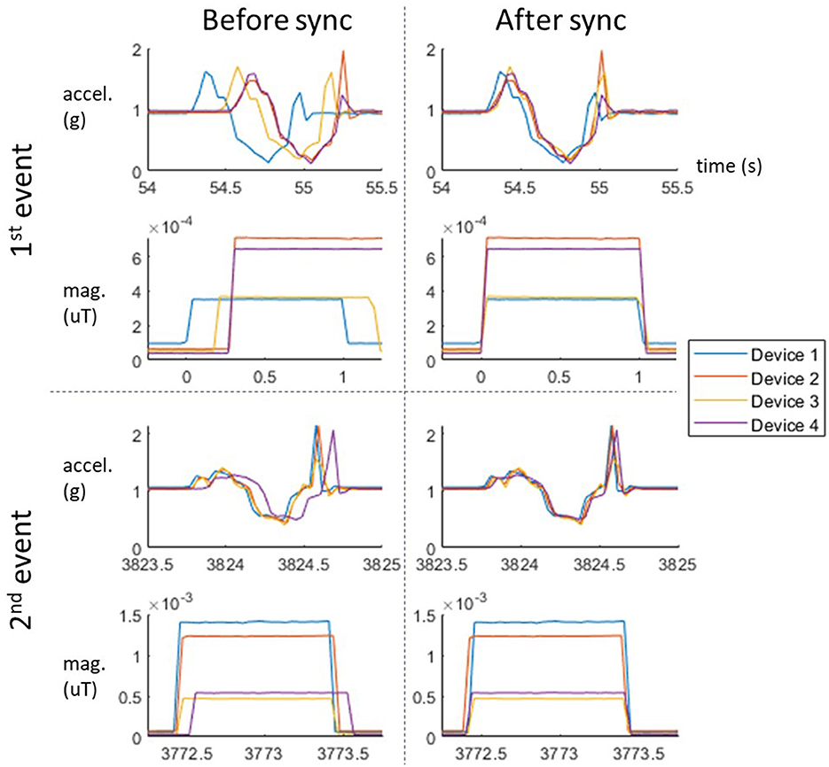
Figure 4. Closeups of 1st and 2nd kinetic (accel.) and EMP (mag.) events before and after synchronization.
2.1.1 EMP vs. kinetic
Because there is no ideal ground truth for the timings, all results are calculated using distinguishable features in the data. One of the limitations on using kinetic events is that the signals have slight variations due to noise and micro-vibrations, thus making precise alignment challenging. This is one of the reasons that expert opinion is typically more accurate than automated correlational methods. Despite the fact that the devices in this experiment are fixed into a container and moved together, the variations in their kinetic responses can still be clearly seen in Figure 4.
In contrast, the rising and falling edges of the EMP events are relatively consistent across devices. The amplitude of the signals varies depending on the distance to the magnetic field generator, however this is less critical for synchronization purposes. The defined edges remove the ambiguity associated with aligning a kinetic event. Because the shape and frequency of the EMP sequence are user-defined, it can be configured to provide additional information, such as unique identifiers to differentiate separate experiments or repeated sync events. In the rest of the paper, we make use of this flexibility to solve the problem of sample-rate limited accuracy.
2.1.2 Limitations on synchronization accuracy
After EMP synchronization, the offsets measured by the kinetic event for devices 2–4 are indistinguishable (<3 ms). However, device 1 retains an offset of between 34 and 37 ms compared to the other devices during the first event (as visible in the top right kinetic plot of Figure 4 and shown in the right 2 columns of Table 1). This post-synchronization offset is a result of the limitation imposed by the sampling rate. With a sample period s, a lower than s alignment error cannot be guaranteed using only a single synchronization edge. Given a sample frequency of 25 Hz, a synchronization error of up to 1/25=40 ms is possible. In the case of the MetaMotion R3 the magnetometer can be configured to sample up to 300 Hz giving a potential maximum error of ~3.3 ms. However, such a high sample rate is not always possible—nor desirable—for some applications when battery life and storage capacity is an issue.
3 Expanded method using multiple pulses
The accuracy of the fixed-pulse width method described above is fundamentally limited by the magnetometer sample rate. The expanded method described below bypasses this limitation by using a sequence of variable length pulses to locate a synchronization event with sub-sample-rate accuracy. Specifically, the method involves transmitting a fixed-width pulse w followed by a sequence of slightly longer pulses until alignment is achieved.
The relationship between sample rate and capturing an EMP square wave can be formalized as follows. If we say that m is the difference between an EMP edge and the next sample point, then m must be 0 ≤ m<s for a sample period of s. If the sample period decreases (rate increases), then the largest difference between the EMP edge and sample point will also decrease.
If a square pulse has a width of w and a sample period s, then it is expected that the pulse will be sampled k = w/s times during its duration. Note that w should be a factor of s. However, if m is 0 an additional sample point is taken on the falling edge, making the total number of sample points k+1, this phenomenon can be seen in Figure 5.
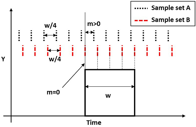
Figure 5. Example demonstrating how the alignment m dictates the number of samples capturing a pulse. Here the sample rate is 1/4 pulse width, w. With m > 0 set A captures the pulse using four samples, while set B with m = 0 uses five samples.
The expanded method uses this phenomenon to understand the alignment of the square EMP pulses to the set of captured samples. This is done by transmitting an initial square pulse with width w and several further pulses with a width of w+a, where a is the shift amount. This shift will result in the m value being reduced by the shift amount, a, after the next pulse, as shown after Pulse 1 in Figure 6. The following pulses will then have a distance m−(p−1)a, where p is the pulse number, between the rising/falling edge and the first sample. With each successive pulse, the distance between an EMP edge and the first sample point will decrease. Eventually the distance will be small enough to allow an additional sample point. This can be seen for the three samples, highlighted by dashed red lines, that fit within Pulse 3 in Figure 6.
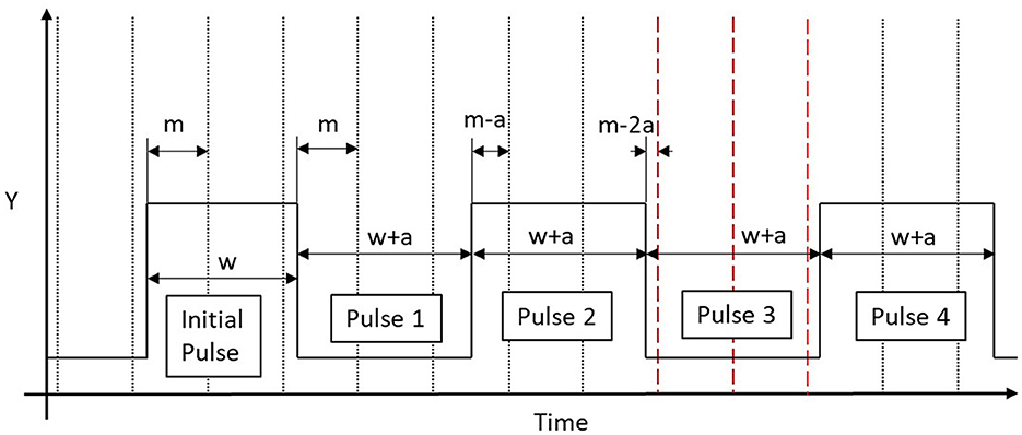
Figure 6. A graphical representation of the extended method demonstrating how the distance, m, between the starting edge of each pulse and the next sample reduces by the extended width, a. Note how pulses 1 and 2 only have two samples between the edges of the pulse, while pulse 3 has an additional sample point between its edges.
It is possible to determine within a range the initial m value from knowing the chosen a and which pulse has the additional sample point. For example if Pulse 1 has an additional sample point then 0 <m ≤ a, as this increase of a allows enough time for the additional sample point to occur on the pulse. Every subsequent pulse has an additional a shift from the initial pulse meaning (p−1)a<m ≤ pa is true. Therefore the shift amount, a, can be seen as a parameter which sets the maximum error. However reducing a also increases the number of possible shifts required to guarantee an additional sample will capture a pulse. The minimum number of pulses required to guarantee the additional sample is s/a+1. For example if the desired maximum error is 5 ms and the sample period is 40 ms, then the full synchronizing signal will need to be at least 9 pulses long (40/5+1 = 9).
The transient response of the electromagnet is also a crucial limiting factor. The solenoid used in this experiment no longer had a stable transient response below a w of 300 ms. Therefore considering that s must be a factor of w and the default s for the module used is 40 ms, it was decided to use a w of 320 ms. The length of the synchronizing signal is then calculated by s(w+a)/a+w. With w=320 ms, the nine pulse sequence signal will take 2.92 s.
3.1 Additional encoding
Although not essential for the functioning of the method described, it can be useful for some applications to encode further information into the EMP signal. For example, an identifying label might be added to address any issues with large offsets between the portable-EMPG RTC and any IMU RTC, which could lead to confusion and mis-identification of signals, see Figure 7.
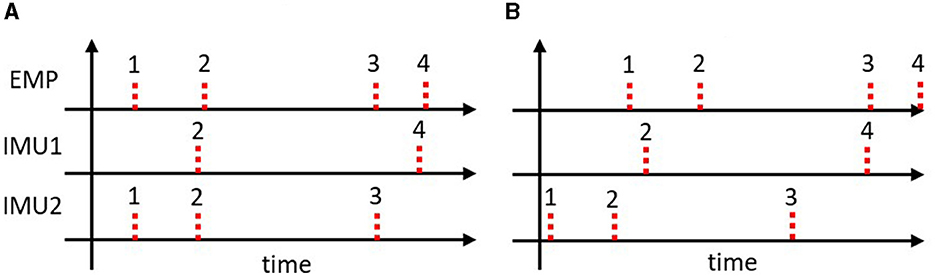
Figure 7. Example EMP events demonstrating typical and extreme de-synchronization for two IMUs. (A) Demonstrates how it is possible to associate the sync events from the portable-EMPG to the IMUs without a label using just their approximate location. (B) Demonstrates how a greater offset between the RTCs of the portable-EMPG and the IMUs requires a label to determine which events belong together: for both IMU1 and IMU2 the 2nd event could be mistaken for the 1st if the labels were not present.
Here we append a unique identifier number to the signal. This customizable label is appended after the synchronization signal, facilitating correspondence between the central records on the EMP and the signals obtained from the IMUs. The trade-off, however, is an increase in signal length, resulting in an extended time required to transmit the sequence of pulses. The signal length is dependent on the w value as well as the desired identifier word length, n. The desired number of bits would be chosen considering the number of synchronization events required for an experiment. In addition to the identifying bits, one start and one stop bit are added to the signal. The identifier length is ~w×(n+2). Therefore a 4-bit word identifier with a w value of 320 ms would last an additional 1.92 s.
If the de-synchronization of EMP is negligible compared to the time between synchronizing events, the removal of the identifier becomes a viable option, allowing for a reduction in synchronization time without compromising the synchronization quality.
3.2 Experimental setup
The EMPG of Figure 1 was adapted to incorporate an RTC such that the EMP events could have a centrally recorded reference timestamp. Additionally, the electromagnet was removed from the holder so that it could be brought to individual IMUs. This new portable-EMPG uses a low-power electromagnet that could be directly powered by an Arduino MKR 1010 board (provided by SeeedStudios).1 The experiment is conducted on a level surface, specifically a flat table, for two sessions of 2 h each using multiple IMUs (MetaMotionRs) whose data is recorded through the MetaBase app. Eight IMU devices were set up to record accelerometer and magnetometer data at a sample rate of 25 Hz. Meanwhile, a 60 FPS video was recorded, showing a laptop displaying the Unix timestamp using the website (time.is/Unix_time) while the events occurred. This recording allowed a timestamp to be taken of the synchronization events. This timestamp was then used to locate the events on MATLAB during post-processing.
The first event begins with generating an EM pulse using the portable-EMPG for each of the eight IMUs. Following this, the IMUs are placed into a 3D-printed container, designed to reduce the independent motion of the devices. Once all are placed in the container, the container is quickly lifted and hit back onto the table, creating a kinetic event. Following 2 h of recording arbitrary accelerometer and magnetometer data of the devices on the table, the IMU devices were removed from the container and the EMP event was repeated for each of the IMUs individually, while the IMUs were placed on the table with their Z-axis facing up. Following this, the IMUs were placed back into the container and a second kinetic event was performed. The orientation-invariant magnitude (Euclidean norm) was calculated for all data.
3.3 Procedure
We conducted two separate 2-h experiments to evaluate the method. One was conducted with an a value of 5 ms, while the other involved a combination of 10 and 20 ms. These parameters were chosen based on successive halving of the sample period (40 ms). The 2nd experiment, using 10 and 20 ms, demonstrates that rapid less accurate synchronizations as well as slower more accurate synchronizations can be performed within a single session. Each of the IMUs were synchronized using the methods previously described: using RTC timestamps only, using the original EMP method from the preliminary study, using the expanded EMP method described in this paper, and using cross-correlation of kinetic events. The cross-correlation of kinetic events was calculated by windowing the kinetic event, interpolating the timestamps and using the xcorr() method on MATLAB to determine the lag that results in the greatest correlation between the different IMUs; the IMUs time series were then translated by this lag value. All offsets are calculated with respect to the expert opinion based on the kinetic events.
3.4 Results
Figure 8 shows an example of the expanded EMP event sequence from one of the IMUs in this experiment. Note how the 3rd pulse has nine sample points while the other pulses only have 8. This indicates that the EMP event is offset by up to 15 ms (3*5 ms) and must be adjusted accordingly.
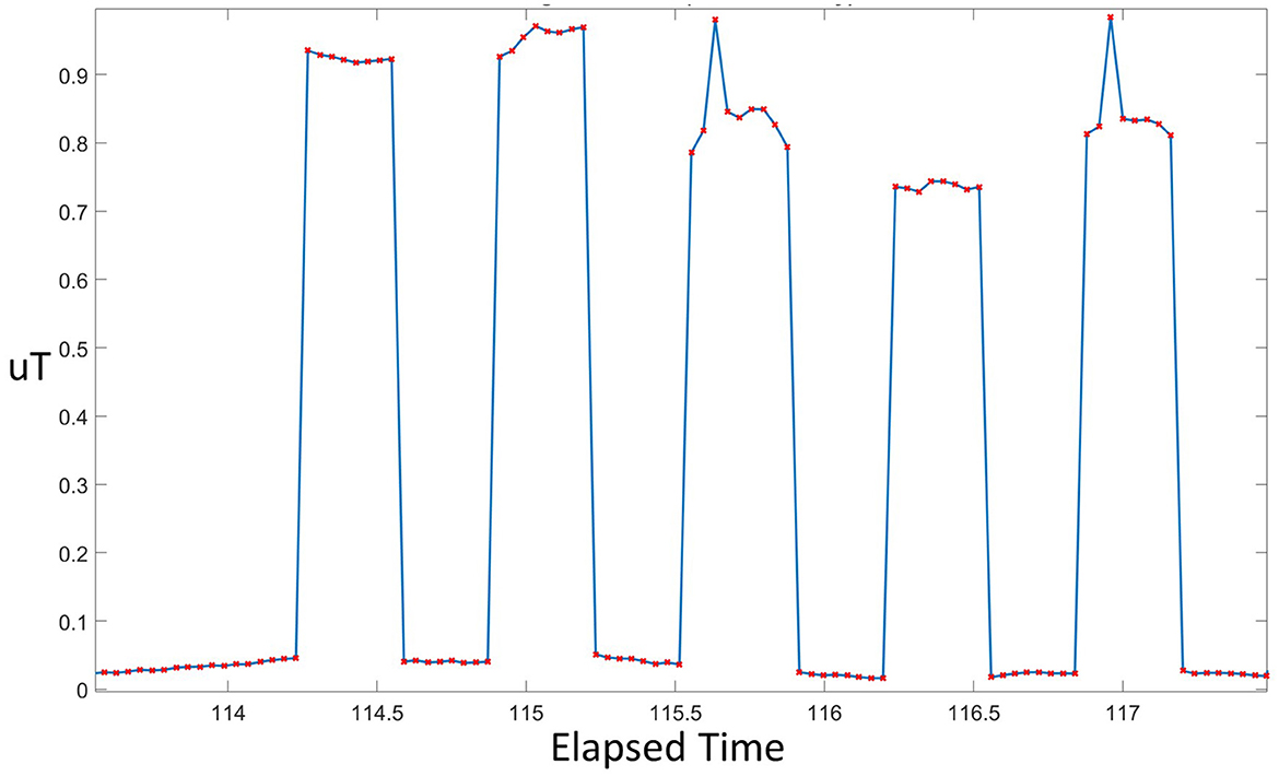
Figure 8. Electromagnetic pulses sampled by an IMU with the pulse width set to give a maximum error of a= 5 ms. Note that the 9-sample situation occurs during the 3rd pulse.
The signal offsets for each IMU are presented in Table 2 (for a=5 ms) and Table 3 (for a=10 and 20 ms) for the four synchronization scenarios. The plots in Figure 9 also show the kinetic events of all IMUs across the four scenarios at a=5 ms.

Table 2. Offsets (in ms) vs. expert opinion for four methods: RTC synchronization, original EMP method, expanded EMP method with a=5 ms, and kinetic event + cross-correlation method.
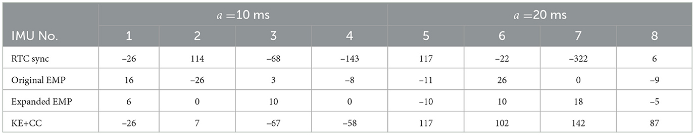
Table 3. Offsets (in ms) vs. expert opinion for four methods: RTC synchronization, original EMP method, expanded EMP method wth a=10 ms (IMU1-4) and a=20 ms (IMU5-8), kinetic event + cross-correlation.

Figure 9. The 1st kinetic event signals of nine devices after (A) RTC sync (B) standard EMP sync (C) kinetic event + cross corr (D) expanded EMP sync (E) expert opinion. Note that the output obtained using the expanded method is most similar to the expert opinion.
As found in the preliminary study, the RTC-only synchronization performs worse of all, with offset errors between 3 ms (Device 1) and up to 336 ms (Device 7). The original EMP method improves this by capping errors within the 40 ms sample period, with the largest error being 36 ms (Device 2).
Across all devices and a settings, the expanded method produces results most closely aligned with expert opinion. Table 2 reveals absolute offsets across the recording of no more than 7 ms for the expanded EMP method (Device 4), as comparable to offsets of up to 36 ms for the original EMP (Device 2). Similarly, for the 2nd experiment with a = 10 in Table 3, the maximum recorded offset is 10 ms (Device 3), and for a = 20, the maximum is 18 ms (Device 7). These values align closely with what might be expected from the desired a settings.
Although most of the results for the expanded method fall within the specified a value, for two devices the offset rises above this (Devices 1 and 4 in Table 2). This is explained by the additional transient response time of the electromagnet, which can be up to 3 ms. So whereas in an ideal system the offset error would be capped at a, in a real system this would actually be (a+3) ms.
Notably, the kinetic cross-correlation method achieves a very high variability in error - from between 3 ms (Device 1, Table 2) to as much as 142 ms (Device 7, Table 3). This can best be explained by the reliance of this method on calculating correlations across accelerometer signals that are noisy. Although plot (c) in Figure 9 achieved the highest between device correlation scores, it is clearly not as well-aligned as the expert-based alignment of plot (e)—or indeed the expanded EMP method shown in plot (d).
4 Discussion
The main goal of this paper is to demonstrate an in-situ synchronization method which is able to achieve sub sample accuracy without requiring any modifications to the hardware or firmware of commercial IMUs.
A simple method of using electromagnetic pulses was first demonstrated that achieves an accuracy dependent on the sample frequency. An expanded method then demonstrated how sub-sample accuracy can be achieved using encoded pulses and a central RTC.
Unlike in similar methods, the method demonstrated here does not heavily rely on the amplitude of the recorded event. The method only requires that the edges of the synchronizing signal are distinguishable. The distances between the IMU devices and the synchronizing unit do not need to be fixed, instead the IMU device must only be within the active range of the portable-EMPG. This means IMU devices are not required to be removed from their experimental setup to be synchronized, which is particularly useful when deploying a large number of IMU devices in wearables. Similar methods require the devices to be removed from the participants and placed into a synchronization box, which when working with a large number of IMUs can be a long process prone to mislabeling. Additionally, the size of the synchronization box limits the number of IMUs that can be used in the experiment as similar methods require all the devices to be synchronized simultaneously. The method demonstrated by this paper does not require a synchronization box nor simultaneous synchronization meaning there is no limit to the number of IMUs that be synchronized.
Two configurations of the expanded multi-pulse method were demonstrated, with the maximum error parameters set as a= 5 ms and a combination of a=10 and a= 20 ms. Note all three accuracy values are sub-sample accuracy, which for a 25 Hz magnetometer is 40 ms. The first configuration shows how the method can be used to achieve low synchronization offset comparable to similar studies, while the second configuration shows how the user could choose to go with quicker synchronization events when low offsets are not required. Additionally, the second configuration also shows how multiple offset values can be used in a single session, giving the user of the method even more flexibility, allowing them to choose an appropriate offset on the fly in response to live events.
4.1 Limitations
Although the expanded method synchronizes IMUs using the edges rather than the amplitude of the received signals, it still needs to be guaranteed that the signal can be distinguished from the noise background. Currently, the system is limited by the Electromagnetic Field (EMF) Regulations from applying powerful electromagnets (ICNIRP, 2009). This constrains the maximum effective distance for synchronization between EMPG and IMUs. The current active range of 11 cm limits the number of applications this method will be effective in, requiring small synchronization points. One caveat to this limitation is that the portability of the proposed method, and the fact that a central reference RTC is used, means that these synchronization points can simply be brought close to wherever each IMU is located if the experiment permits it.
A further limitation of this method is that the synchronization of all devices is dependent on the central RTC of the EMPG. This RTC is also susceptible to drift. Figure 3 is a timing diagram showing the offsets and drifts associated with the inaccuracies of an RTC. This diagram shows how two IMUs with opposing offsets and drifts can result in large de-synchronization of clocks. Note that in this diagram the drift of the electromagnetic generator's RTC is less than the two IMUs, in practice this may not be the case as this method is focused on synchronizing the clocks of multiple IMUs rather than determining absolute timing.
In situations where the portable-EMPG's RTC could induce significant desynchronization, then an additional 6-bit identifier can be appended to the signal to help differentiate sync events. The downside to this is that it would result in an extended synchronization time (1.92 s in the example given in this paper).
Overall, the expanded method can achieve higher synchronization performance by increasing the signal length; however, degree of accuracy is constrained by the transient response of the electromagnet. In experiments, the transient response resulted in an approximate width of 3 ms for each edge, which is a factor that should be taken into consideration when employing this approach.
5 Conclusion
This paper introduces a new method for synchronizing wearable IMUs using a portable electromagnetic pulse generator (portable-EMPG) to transmit magnetic pulses. This approach potentially enables synchronization of multiple wearable IMUs without requiring their removal from users. Through experiments with different maximum degrees of error (5, 10, and 20 ms), we demonstrate the method's flexibility in adjusting synchronization accuracy to user requirements. The trade-off is that more precise synchronization requires a longer sequence of EMP events. Additionally, we introduce the idea of using further encoding on the electromagnetic pulse to act as an identifier, allowing the user to identify specific events with a binary word.
Our study identifies a 3 ms error related to the solenoid's transient response and acknowledges drift and offset errors associated with synchronizing to a central RTC. Future research will focus on extending the portable-EMPG's active range and improving timestamp accuracy through Wi-Fi integration. These advancements aim to enhance the reliability and effectiveness of the synchronization technique, making it applicable across various domains reliant on precise IMU data synchronization. This work contributes to the development of synchronization methodologies in inertial measurement systems, promising improved data accuracy and usability in practical applications.
Data availability statement
The datasets presented in this study can be found in online repositories. The names of the repository/repositories and accession number(s) can be found in the article/supplementary material.
Author contributions
TG: Conceptualization, Formal analysis, Methodology, Project administration, Supervision, Validation, Visualization, Writing – original draft, Writing - review & editing, Data curation, Investigation, Software. ZL: Conceptualization, Data curation, Formal analysis, Investigation, Methodology, Software, Visualization, Writing - original draft. SD: Writing – original draft, Supervision. AH: Writing – original draft, Funding acquisition. JW: Funding acquisition, Writing – original draft, Conceptualization, Formal analysis, Methodology, Project administration, Resources, Supervision, Validation, Visualization, Writing – review & editing.
Funding
The author(s) declare that financial support was received for the research, authorship, and/or publication of this article. This work was funded in-part by the ERC SocSensors Project (Ref: 899779).
Conflict of interest
The authors declare that the research was conducted in the absence of any commercial or financial relationships that could be construed as a potential conflict of interest.
The author(s) declared that they were an editorial board member of Frontiers, at the time of submission. This had no impact on the peer review process and the final decision.
Publisher's note
All claims expressed in this article are solely those of the authors and do not necessarily represent those of their affiliated organizations, or those of the publisher, the editors and the reviewers. Any product that may be evaluated in this article, or claim that may be made by its manufacturer, is not guaranteed or endorsed by the publisher.
Footnotes
1. ^SeeedStudios Grove Electromagnet: https://wiki.seeedstudio.com/Grove-Electromagnet/.
References
Bannach, D., Amft, O., and Lukowicz, P. (2009). “Automatic event-based synchronization of multimodal data streams from wearable and ambient sensors,” in Smart Sensing and Context, Lecture Notes in Computer Science, eds. P. Barnaghi, K. Moessner, M. Presser and S. Meissner (Berlin; Heidelberg: Springer), 135–148.
Bian, S., Liu, M., Zhou, B., and Lukowicz, P. (2022). The state-of-the-art sensing techniques in human activity recognition: a survey. Sensors 22:4596. doi: 10.3390/s22124596
Bulling, A., Blanke, U., and Schiele, B. (2014). A tutorial on human activity recognition using body-worn inertial sensors. ACM Comput. Surv. 46, 1–33. doi: 10.1145/2499621
Gao, N., Shao, W., Rahaman, M. S., and Salim, F. D. (2020). n-gage: predicting in-class emotional, behavioural and cognitive engagement in the wild. Proc. ACM Interact. Mob. Wearable Ubiquit. Technol. 4:3411813. doi: 10.1145/3411813
Gilbert, T., Day, S., Hamilton, A. F. D. C., and Ward, J. (2022). “A simple method for synchronising multiple imus using the magnetometer,” in Proceedings of the 2022 ACM International Symposium on Wearable Computers, ISWC '22 (New York, NY: Association for Computing Machinery), 100–102.
Gravina, R., Alinia, P., Ghasemzadeh, H., and Fortino, G. (2017). Multi-sensor fusion in body sensor networks: state-of-the-art and research challenges. Inform. Fusion 35, 68–80. doi: 10.1016/j.inffus.2016.09.005
Guo, X., Mohammad, M., Saha, S., Chan, M. C., Gilbert, S., and Leong, D. (2016). “PSync: visible light-based time synchronization for Internet of Things (IoT),” in IEEE INFOCOM 2016—The 35th Annual IEEE International Conference on Computer Communications (Piscataway, NJ: IEEE), 1–9.
Hoelzemann, A., Odoemelem, H., and Van Laerhoven, K. (2019). “Using an in-ear wearable to annotate activity data across multiple inertial sensors,” in Proceedings of the 1st International Workshop on Earable Computing, 14–19. doi: 10.1145/3345615.3361136
ICNIRP (2009). ICNIRP statement on the “guidelines for limiting exposure to time-varying electric, magnetic, and electromagnetic fields (up to 300 ghz). Health Phys. 97, 257–258. doi: 10.1097/HP.0b013e3181aff9db
Idrees, Z., Granados, J., Sun, Y., Latif, S., Gong, L., Zou, Z., et al. (2020). IEEE 1588 for clock synchronization in industrial IoT and related applications: a review on contributing technologies, protocols and enhancement methodologies. IEEE Access 8, 155660–155678. doi: 10.1109/ACCESS.2020.3013669
Li, D., and Sinha, P. (2012). Rbtp: low-power mobile discovery protocol through recursive binary time partitioning. IEEE Trans. Mob. Comput. 13, 263–273. doi: 10.1109/TMC.2012.240
Luo, C., Koski, H., Korhonen, M., Goncalves, J., Anagnostopoulos, T., Konomi, S., et al. (2017). “Rapid clock synchronisation for ubiquitous sensing services involving multiple smartphones,” in Proceedings of the 2017 ACM International Joint Conference on Pervasive and Ubiquitous Computing and Proceedings of the 2017 ACM International Symposium on Wearable Computers, UbiComp '17 (New York, NY: Association for Computing Machinery), 476–481.
Plotz, T., Chen, C., Hammerla, N. Y., and Abowd, G. D. (2012). “Automatic synchronization of wearable sensors and video-cameras for ground truth annotation—a practical approach,” in 2012 16th International Symposium on Wearable Computers (Newcastle: IEEE), 100–103.
Raman, C., Tan, S., and Hung, H. (2020). “A modular approach for synchronized wireless multimodal multisensor data acquisition in highly dynamic social settings,” in Proceedings of the 28th ACM International Conference on Multimedia, MM '20 (New York, NY: Association for Computing Machinery), 3586–3594.
Rowe, A., Gupta, V., and Rajkumar, R. (2009). “Low-power clock synchronization using electromagnetic energy radiating from ac power lines,” in Proceedings of the 7th ACM Conference on Embedded Networked Sensor Systems (Berkeley, CA), 211–224. doi: 10.1145/1644038.1644060
Spilz, A., and Munz, M. (2023). Synchronisation of wearable inertial measurement units based on magnetometer data. Biomed. Eng. 2021:329. doi: 10.1515/bmt-2021-0329
Sun, Y., Greaves, D. A., Orgs, G., de C. Hamilton, A. F., Day, S., and Ward, J. A. (2023). Using wearable sensors to measure interpersonal synchrony in actors and audience members during a live theatre performance. Proc. ACM Interact. Mob. Wear. Ubiquit. Technol. 7, 1–29. doi: 10.1145/3580781
Wang, C., Sarsenbayeva, Z., Luo, C., Goncalves, J., and Kostakos, V. (2019). “Improving wearable sensor data quality using context markers,” in Adjunct Proceedings of the 2019 ACM International Joint Conference on Pervasive and Ubiquitous Computing and Proceedings of the 2019 ACM International Symposium on Wearable Computers, 598–601. doi: 10.1145/3341162.3349334
Ward, J. A., Pirkl, G., Hevesi, P., and Lukowicz, P. (2017). “Detecting physical collaborations in a group task using body-worn microphones and accelerometers,” in 2017 IEEE International Conference on Pervasive Computing and Communications Workshops (PerCom Workshops) (Kona, HI: IEEE), 268–273.
Ward, J. A., Richardson, D., Orgs, G., Hunter, K., and Hamilton, A. (2018). “Sensing interpersonal synchrony between actors and autistic children in theatre using Wrist-Worn accelerometers,” in Proceedings of the 2018 ACM International Symposium on Wearable Computers, ISWC '18 (New York, NY: Association for Computing Machinery), 148–155.
Wolling, F., Huynh, C. D., and Van Laerhoven, K. (2021a). “IbSync: intra-body synchronization of wearable devices using artificial ECG landmarks,” in Proceedings of the 2021 ACM International Symposium on Wearable Computers, 102–107. doi: 10.1145/3460421.3478815
Wolling, F., van Laerhoven, K., Siirtola, P., and Röning, J. (2021b). “PulSync: the heart rate variability as a unique fingerprint for the alignment of sensor data across multiple wearable devices,” in 2021 IEEE International Conference on Pervasive Computing and Communications Workshops and other Affiliated Events (PerCom Workshops) (Kassel: IEEE), 188–193.
Keywords: Wearabe sensors, Synchronization, IMU (Inertial measurement unit), Magnetic field sensor, multisensor
Citation: Gilbert TJ, Lin Z, Day S, Hamilton AFdC and Ward JA (2024) A magnetometer-based method for in-situ syncing of wearable inertial measurement units. Front. Comput. Sci. 6:1385392. doi: 10.3389/fcomp.2024.1385392
Received: 12 February 2024; Accepted: 04 April 2024;
Published: 19 April 2024.
Edited by:
Bo Zhou, German Research Center for Artificial Intelligence (DFKI), GermanyReviewed by:
Sizhen Bian, ETH Zürich, SwitzerlandPhilipp Marcel Scholl, University of Freiburg, Germany
Copyright © 2024 Gilbert, Lin, Day, Hamilton and Ward. This is an open-access article distributed under the terms of the Creative Commons Attribution License (CC BY). The use, distribution or reproduction in other forums is permitted, provided the original author(s) and the copyright owner(s) are credited and that the original publication in this journal is cited, in accordance with accepted academic practice. No use, distribution or reproduction is permitted which does not comply with these terms.
*Correspondence: Thomas J. Gilbert, dGhvbWFzLmouZ2lsYmVydEB1Y2wuYWMudWs=