 Xin Liu1Zhiwei Wang1Wenzhuo Wang1
 Yunling Lv2*Bo Yuan1Shijie Wang1Wujing Li1Qiufang Li1Qiwen Zhang1Qianchang Chen1
- 1Northwest Branch of State Grid Corporation of China, Xi’an, China
- 2School of Electrical Engineering, Xi’an University of Technology, Xi’an, China
In order to reduce the chattering caused by the discontinuity of the control function in the traditional sliding mode observer (SMO), this article proposes a sliding mode observer with phase-locked loop (PLL) to estimate the speed and position of the rotor. The back electromotive force (EMF) of a permanent magnet synchronous motor (PMSM) in a static coordinate system is accurately estimated by SMO, and then, PLL is constructed to combine the observed rotor position angle and back EMF to compensate the phase lag in angle estimation so as to obtain a more accurate speed. It solves the problems of poor robustness and complex algorithms in the traditional SMO prediction algorithm. The simulation results show that the SMO with PLL can effectively reduce the system chattering and effectively improve the accuracy of rotor speed and position estimation.
1 Introduction
Since electric drives for propulsion can eliminate the need for shafts and gearing while increasing vehicle stealth and power system flexibility, there has been a large number of advances on permanent magnet synchronous motors (PMSMs) for vehicle propulsion in power semiconductors, magnetic materials, and energy storage systems (Liu et al., 2018; Nguyen et al., 2018; Cui et al., 2020; Liu et al., 2021; Zhang et al., 2021; Fu et al., 2022). Novel propulsion configurations are pushing the need for the PMSM to operate at the location where torque is required, which in many propulsion systems is a harsh environment due to severe moisture, humidity, vibration, or temperature. In order to achieve accurate, fast, and small overshoot control of PMSM, the key part is to determine the position information and speed of the rotor magnetic pole. Generally speaking, mechanical sensors are installed to collect the specific parameter information of the signal through the photoelectric encoder and other sensors (Bourogaoui et al., 2017; Cao et al., 2020; Xu et al., 2021; Xiong et al., 2022). However, these sensors require the additional mounting space, increase the cost, and reduce the system reliability in environmental constraint. Hence, the sensorless methods have been developed to simplify the structure and reduce the manufacturing cost of the motor.
Currently, a lot of research has been done on the speed sensorless control of PMSM. In a sensorless permanent magnet synchronous motor, we extract the parameters related to speed and position from the stator voltage and current, which are easy to measure at the stator edge, to replace the mechanical sensor, and to realize the motor closed-loop control (Xiong et al., 2016a; Xiong et al., 2016b; Yi et al., 2020). At present, the sensorless control technology of a permanent magnet synchronous motor is mainly divided into three categories: high-frequency signal injection method (Li and Wang, 2018; Xiong et al., 2020; Yu et al., 2021), motor model method (Chen and Pi, 2016; Zhong and Lin, 2017; Luo et al., 2019; Sun et al., 2019; He et al., 2020; Rongyn et al., 2020), and intelligent algorithm (Urbanski and Janiszewski, 2019; Lu et al., 2020; Ma et al., 2020). Since high-frequency signal injection methods may affect the current signal and many artificial intelligence methods are still in the stage of simulation and theoretical exploration, motor model-based methods are widely used and they have received considerable research attention in the past few years.
The sliding mode observer (SMO) method is one of the algorithms based on the motor model. Compared with other methods, the SMO method is not sensitive to system parameter changes and external disturbances, so it has attracted extensive attention of experts and scholars, see Jin et al. (2014), Lin et al. (2014), Li et al. (2015), Zhang et al. (2016), Zhang et al. (2019), and Hu et al. (2020) and references therein. Due to the inertia of traditional SMO, the equivalent back EMF value observed by SMO contains high-frequency components, and the estimated value has the problem of chattering, which affects the application of traditional SMO in high-precision occasions, and the angle compensation after low-pass filtering also affects the observation accuracy in practical applications. Aiming at the chattering problem in the estimation of traditional SMO, a rotor position identification method of PLL is proposed based on the effective flux model (Zheng et al., 2015; Zhan et al., 2020; Zhao et al., 2020). The comparison link between the actual rotor position and the estimated rotor position of this method is equivalent to the phase detector in the phase-locked loop model. The one-time integration from the speed to the rotor position is equivalent to the voltage-controlled oscillation in the phase-locked loop model. The speed of the motor is adjusted through the error between the system input signal and the output signal.
This article focuses on eliminating the chattering phenomenon of traditional SMO in estimating rotor position and speed. Distinguished from traditional SMO, a sensorless control of the permanent magnet synchronous motor based on SMO with PLL has been designed to improve the accuracy of rotor speed and position estimation. Compared with the literature (Li and Wang, 2018; Yi et al., 2020; Yu et al., 2021), the main contributions of this article can be outlined as follows:
(1) The system and measurement have been modeled to formulate the state estimation problem for PMSM. The research of this problem has great significance for establishing an accurate PMSM mathematical model and selecting which algorithm to estimate the speed and position of the motor rotor in the next step.
(2) We propose an estimation scheme to weaken chattering. The function of the PLL controller is to adjust
(3) The simulated comparison between the proposed method and the traditional SMO shows that the proposed method can effectively suppress the jitter of the traditional SMO, and the phase-locked loop is used to track the rotor speed and position, which effectively improves the estimation accuracy, and proves the correctness and feasibility of the proposed method.
The rest of this article is organized as follows: in Section 2, we present the mathematical model of PMSM. In Section 3, we analyze the principle of the SMO with the PLL control scheme and present main results. A simulation result is used to verify the proposed method in Section 4. Finally, Section 5 concludes this article.
2 Mathematical Model of the Permanent Magnet Synchronous Motor
PMSM is a multivariable, strong-coupling, and nonlinear system. It needs to be simplified in mathematical modeling. Now, the following idealized assumptions are made:
(1) Idealization of the air gap magnetic field: the magnetic field generated by a permanent magnet and three-phase winding is sinusoidal in the air gap, regardless of the end effect and the influence of primary cogging on the magnetic field.
(2) Idealization of the magnetic circuit: the magnetic circuit is linear without considering magnetic leakage, hysteresis, and eddy current.
(3) Idealization of motor parameters: the parameters of the motor remain constant and do not change with the working state of the motor and the external environment.
Through the above assumptions, in order to simplify the mathematical model of PMSM and realize sensorless closed-loop control, correlation transformation must be carried out. Before transformation, the coordinate systems used in the PMSM control principle include the ABC three-phase coordinate system, the αβ two-phase stationary coordinate system, and the dq two-phase rotating coordinate system (Kawabata et al., 2014). The specific positional relationship of the three-coordinate systems is shown in Figure 1. θ is the electrical angle between the rotor shaft (d-axis) and the stator shaft (a-axis), and ω is the synchronous speed.
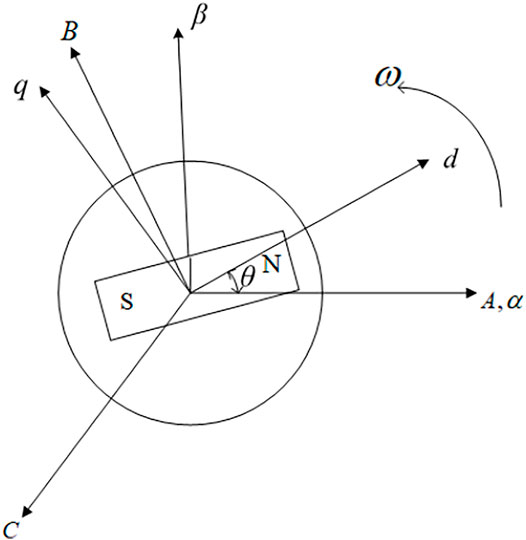
FIGURE 1. Coordinates of PMSM.
The voltage equation of PMSM in the αβ axis rotating coordinate system is as follows:
where uα and uβ are the voltages of the α and β axes, respectively; iα and iβ are the currents of the α and β axes, respectively; ψα and ψβ are the fluxes of the α and β axes, respectively; and Rs is the stator resistance.
The flux linkage equation is
where Lα and Lβ are the inductances of the α and β axes, respectively, in the surface-mounted PMSM, Lα = Lβ = L. ψf is the rotor flux, and θ is the rotor position.
Combining Eqs 1, 2, we can obtain that
where ω is the rotor angular speed,
Arranging Formula 3, we obtain
when
The PMSM mathematical model of Eq. 4 can be written as
where eα and eβ are the back electromotive forces (EMFs) of the α and β axes, respectively. It can be seen from Eq. 5 that the back EMFs eα and eβ contain all the information of rotor position. Therefore, only by accurately obtaining the back EMF, the speed and position information of the motor be calculated.
3 Permanent Magnet Synchronous MotorVector Control Based on the Sliding Mode Observer and Phase-Locked Loop
Through the derivation of the mathematical model, we can see that the back EMF of PMSM has the sinusoidal waveform and cosine waveform, which contains the rotation angle, speed, and flux linkage information of the motor. It can be seen from Eq. 5 that the phase of the back EMF is related to the rotation angle of the motor, and the amplitude of the back EMF is related to the speed of the motor. The position and speed of the rotor can be obtained as
In this article, the sliding mode observer (SMO) is used to estimate the back EMF of the motor. The basic principle is to estimate the back EMF eα, eβ of the PMSM by using the SMO, then filter the high-frequency harmonics through the low-pass filter to obtain
3.1 The Principle of the Sliding Mode Observer
Synovial variable structure control is a nonlinear control based on the control switching rule. Through the mutual switching between different control states, the current state quantity of the system moves according to the set state trajectory so that the actual operation state of the system is infinitely close to the expected value. The biggest difference between sliding mode variable structure control and conventional control is that the sliding mode control is discontinuous, that is, a switching intermittent control in which the system structure changes with time. By switching between different controls, the current state of the system moves according to the predetermined “sliding mode” state trajectory so that the system reaches the desired point so as to realize the control of the system. Because this sliding mode is independent of the system parameters and disturbances, the system has good robustness.
Let the general nonlinear system be expressed as
where x ∈ Rn, u ∈ Rm are the state and control variables of the system, respectively.
If there is a hypersurface s(x) = s (x1, x2, …, xn) = 0 and the system space is divided into two parts with s = 0 as the boundary, namely, s > 0 part and s < 0 part, then there are three motions A, B, and C as shown above in this region, as shown in Figure 2.
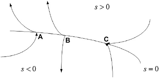
FIGURE 2. Synovial hypersurface division.
Among them, C motion cases have a special significance for sliding model control. If all moving points in an area on the switching surface are similar to C, that is, once the moving point approaches this area, it will approach and finally stabilize in this area. At this time, the region where all motion points on the switching surface s = 0 is called the “sliding mode region,” and the motion of the system in the sliding mode region is called the “sliding mode motion”. Therefore, when the termination point reaches the adjacent area of the switching surface s = 0, there must be
The above formula can also be written as
To determine the sliding mode, it is necessary to determine whether the switching function s(x), s ∈ Rm·u(x) is the control function of the system, and its value changes with the value of s(x); the change relationship is as follows
Among them, u+(x) ≠ u−(x). It can be seen from Eq. 11 that in order to determine the control function, the switching function must be obtained. If the transformation mode of u(x) is different, the structure of the system will also change. However, no matter how the system structure changes, the following three conditions must be met before the system has the characteristics of the synovial variable structure control:
(1) Existence: the switching function u(x) exists and the state trajectory can run on the synovial surface to reach the equilibrium point; Eq. 11 must be satisfied.
(2) Accessibility: all moving points outside the sliding mode surface s(x) will reach the sliding mode surface in a finite time.
(3) Stability: ensure the stability of synovial movement; the condition
3.2 Design of the Sliding Mode Observer
The motion of the synovial variable structure control system is divided into two processes. The first process is that the system moves from any direction to the switching surface until it moves to the switching surface; for this process, s ≠ 0. The second process is to make the system enter the switching surface and move along the switching surface. Therefore, the task of designing synovial variable structure control is also divided into two stages. The task of the first stage is to make the system reach the sliding mode, and the task of the second stage is to make the system maintain the sliding mode. In the actual operation process, the rotor current is more convenient to measure, so the current curve is usually selected as the switching surface. The design steps of the synovial current observer are as follows: 1) a synovial current observer is designed based on the PMSM two-phase static coordinate system model; 2) the observed current is derived from the synovial current observer model; 3) the state equation of the current error is obtained by making a difference between the observed value of current and the actual value of current; 4) the observed value of back EMF is obtained from the error equation, and the rotor position θ can be estimated according to the observed value of back EMF; and 5) the angular speed ω can be obtained by differentiating θ. The control structure block diagram of the synovial current observer is shown in Figure 3.

FIGURE 3. Control structure block diagram of the synovial current observer.
Define sliding surface
where
According to the mathematical model of PMSM in the αβ coordinate system, an SMO is constructed
where k is the switching gain, which must meet the existence and accessibility conditions of sliding mode motion. Otherwise, the system cannot perform sliding mode motion.
It can be seen from Eq. 15 that the error dynamic characteristic depends on the unknown back EMF eα, eβ. Select
that is
Similarly,
It can be deduced that to satisfy
where zα, zβ are the switch signals. The signum function
where
Thus, the equivalent value of rotor angle is obtained
The low-pass filter will inevitably introduce phase delay. The phase delay will directly affect the phase response of the low-pass filter. Especially when ω gets lower, the phase delay of the corresponding natural frequency gets bigger. Therefore, it is necessary to make the corresponding phase compensation according to the filter Δθ; the compensation angle is
The correct rotor position can only be obtained after compensation.
Theoretically,
3.3 Sliding Mode Observer With the Phase-Locked Loop
Due to the chattering and the disturbance signal in the back EMF, there are large errors between the speed and rotor position that are extracted by traditional SMO. Therefore, this article designs an SMO based on PLL; it has good follow-up to phase and frequency and can also omit the filter link in the original system. Therefore, the observed back EMF
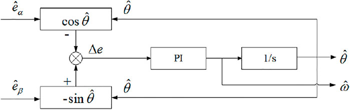
FIGURE 4. Block diagram of PLL control.
As described in Figure 4, the transfer function of the PI regulator is
where kp, ki is the proportional gain and integral gain of the PI regulator, respectively.
PLL generally controls the output frequency through the voltage difference between the phase of the input signal and the phase of the output signal to make it reach the desired frequency value. At this time, the phase difference of the signal remains constant and is in the phase locking state. The phase-locked loop based on the phase tracking principle is used to estimate the rotor position and speed, which reduces the disturbance error.
Remark 1A typical phase-locked loop (PLL) system consists of three basic circuits, that is, phase detector (PD), voltage-controlled oscillator (VCO), and loop filter (LPF). The phase detector is a key unit circuit in PLL, which is responsible for the phase comparison of two input signals. The voltage-controlled oscillator is a voltage frequency conversion device. The loop filter is actually a low-pass filter applied to the loop, which filters the stepped waveform output by the phase comparator into smooth DC power.From Figure 4, it can be obtained thatIf
It can be seen that the PLL system has low-pass filtering characteristics, which can filter out the high-frequency chattering component in the estimated back EMF and obtain a rotor position estimation signal with high accuracy. The steady-state error of the equivalent phase-locked loop rotor position detection system shown in Figure 5 is
Hence, the control can be realized in the whole PMSM sensorless system.
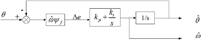
FIGURE 5. Equivalent diagram of PLL control.
4 Numerical Example
As shown in Figure 6, the system structure block diagram of PMSM sensorless control based on SMO and PLL is constructed.
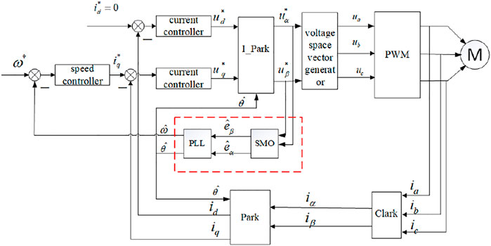
FIGURE 6. System structure block diagram of PMSM sensorless control based on SMO with PLL.
The system adopts a double-loop structure; the inner loop is the current loop and the outer loop is the speed loop. The closed-loop control is completed by using rotor field oriented vector control with id = 0, speed loop PI control, current loop PI control, and the rotor position estimation method based on SMO with PLL. Similar to the traditional SMO, the voltage in the αβ coordinate system is controlled by the SMO and acts with the current, and after the back EMF signal passes through the switching control function and low-pass filter, the rotor position and speed information are obtained by phase-locked loop and phase compensation. The feedback link is used to return the back EMF signal output by the control function to the SMO to realize the closed-loop structure as a whole. This method can realize a stable control system.
In order to verify the feasibility of the above control system, the simulation system model is built in the MATLAB/Simulink environment, and the simulation analysis is carried out. The following are the detailed parameter settings of the simulation. Figure 7 shows the comparison of rotor speed waveforms corresponding to the two methods. It can be seen that the estimated rotor speed corresponding to the two methods is basically consistent with the actual rotor speed. It can be seen from Figure 7A that the given target speed of the motor is 1,000 rad/min. The traditional SMO control can track the expected speed. The estimated speed is almost equal to the actual speed when it is stable, but there will be large chattering in the speed estimation at the moment of low speed and speed change, and there will be large deviation in the speed estimation. It can be seen from Figure 7B that although there is a certain overshoot during startup, there is no chattering and tends to be stable soon. The corresponding speed waveform curve is much smoother. The estimated speed can quickly follow the set speed and converge to the actual speed, which shows that the system has good dynamic and static performance.
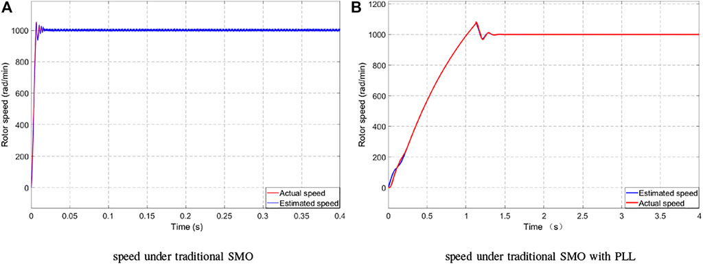
FIGURE 7. Curve between the estimated and actual speeds. (A) Speed under traditional SMO. (B) Speed under traditional SMO with PLL.
TABLE 1. Parameters of PMSM.
Permanent magnet motor vector control is adopted. The simulation conditions are as follows: DC side voltage Udc = 311 V, the pulse width modulation (PWM) switching frequency is 10 kHz, the given speed is 1,000 rad/min; start with no load first, and mainly observe the estimated differences of speed and rotor position in SMO and SMO with PLL.
Using the traditional SMO and the SMO with PLL method proposed in this article, the speed and position simulation diagrams of the traditional SMO control and SMO with PLL are given, respectively.
Figure 8 is a waveform of the deviation between the estimated speed and the actual speed. It can be seen from Figure 8A that the maximum speed estimation error of the traditional synovial observer is 16 rad/min and finally stabilized at 10 rad/min. That is, the steady-state error is 10 rad/min. It can be seen from Figure 8B that the SPM and PLL speed fluctuation has been greatly improved, which not only ensures the real-time tracking of rotor speed but also optimizes the steady-state error of speed. The maximum speed error is only 12 rad/min after stabilization, and the error is basically 0. The steady-state error value is further weakened, which shows that this method has a good filtering effect, strong tracking performance, and small steady-state velocity fluctuation.
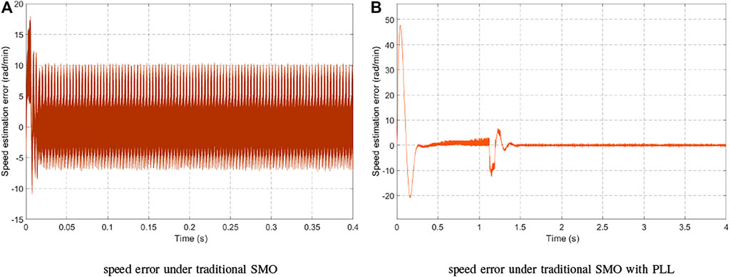
FIGURE 8. Curve between the estimated and actual speed errors. (B) Speed error under traditional SMO. (B) Speed error under traditional SMO with PLL.
Figure 9 is the motor rotor position curve. It can be seen that the estimated rotor position can maintain good consistency with the actual rotor position, which shows that the observer has a good estimation effect. As can be seen from Figure 9A, due to the high-frequency chattering component, the estimated position of the rotor lags behind the actual position, and there is a fixed error, which cannot be corrected and improved and will affect the dynamic response performance of the system. Figure 9B shows that after the PLL is introduced, the output frequency is controlled by the voltage difference between the phase of the input signal and the phase of the output signal to reach the desired frequency value, maintain a fixed phase error, and be in the phase locking state. There is neither phase lag nor amplitude attenuation. The estimated angle is basically the same as the actual angle, which effectively weakens the high-frequency noise and harmonics in the back EMF and makes the output stable, and the control effect more meets the performance control requirements of PMSM.
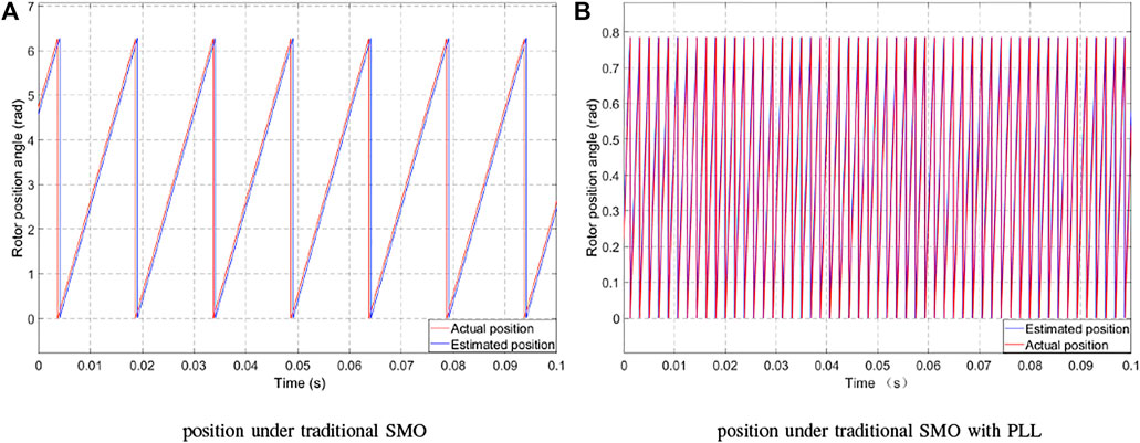
FIGURE 9. Curve between the estimated and actual positions. (A) Position under traditional SMO. (B) Position under traditional SMO with PLL.
Figure 10 is the motor rotor position error curve. The maximum position error obtained by the traditional SMO shown in Figure 10A is 6.1 rad/min, while after the introduction of PLL, the maximum error between the actual position and the estimated position of the motor is .75 rad/min. It shows that the accuracy based on SMO with PLL is improved.
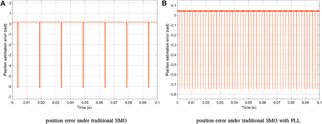
FIGURE 10. Curve between the estimated and actual position errors. (A) Position error under traditional SMO. (B) Position error under traditional SMO with PLL.
5 Conclusion
This article has studied a chattering suppression method based on the combination of SMO and PLL technologies, and the chattering problem of traditional SMO in PMSM sensorless control has been solved. In this method, the SMO has been used to estimate the back EMF, and the phase-locked loop has been employed to estimate the speed and position of PMSM. The design principle of PLL has been analyzed theoretically, and the derivation and verification have been given. Through the simulation of the design scheme, the results show that the SMO with PLL improves the chattering problem of the traditional SMO, has high estimation accuracy of motor speed and rotor position, has a small amount of calculation, and has strong robustness to external interference.
Data Availability Statement
The original contributions presented in the study are included in the article/supplementary material; further inquiries can be directed to the corresponding author.
Author Contributions
All authors listed have made a substantial, direct, and intellectual contribution to the work and approved it for publication.
Conflict of Interest
Authors XL, ZW, WW, BY, SW, WL, QL, QZ, and QC were employed by the company Northwest Branch of State Grid Corporation of China.
The remaining author declares that the research was conducted in the absence of any commercial or financial relationships that could be construed as a potential conflict of interest.
Publisher’s Note
All claims expressed in this article are solely those of the authors and do not necessarily represent those of their affiliated organizations or those of the publisher, the editors, and the reviewers. Any product that may be evaluated in this article or claim that may be made by its manufacturer is not guaranteed or endorsed by the publisher.
References
Bourogaoui, M., Sethom, H. B. A., and Belkhodja, I. S. (2017). Real-Time Encoder Faults Detection and Rotor Position Estimation for Permanent Magnet Synchronous Motor Drives Fault Tolerant Sensorless Control Using Digital Signal Controller. Mathematics Comput. Simulation 131, 253–267. doi:10.1016/j.matcom.2015.09.010
Cao, R., Jiang, N., and Lu, M. (2020). Sensorless Control of Linear Flux-Switching Permanent Magnet Motor Based on Extended Kalman Filter. IEEE Trans. Ind. Electron. 67 (7), 5971–5979. doi:10.1109/tie.2019.2950865
Chen, S., and Pi, Y. (2016). Position Sensorless Control for Permanent Magnet Synchronous Motor Based on Sliding Mode Observer and Sliding Mode Controller. Trans. China Electrotechnical Soc. 31 (12), 108–117. http://dgjsxb.ces-transaction.com/CN/Y2016/V31/I12/108.
Cui, F., Sun, Z., Xu, W., Zhou, W., and Liu, Y. (2020). Comparative Analysis of Bilateral Permanent Magnet Linear Synchronous Motors with Different Structures. Trans. Electr. Mach. Syst. 4 (2), 142–150. doi:10.30941/cestems.2020.00019
Fu, D., Zhao, X., and Zhu, J. (2022). A Novel Robust Super-twisting Nonsingular Terminal Sliding Mode Controller for Permanent Magnet Linear Synchronous Motors. IEEE Trans. Power Electron. 37 (3), 2936–2945. doi:10.1109/tpel.2021.3119029
He, W., Wu, X., Chen, J., and Wang, Y. (2020). Comparative Study of Sensorless Control of Permanent Magnet Synchronous Motor Realised by Sliding‐mode Observer. IET Power Electron. 13 (6), 1191–1199. doi:10.1049/iet-pel.2019.1153
Hu, J., Shao, Y., Zhou, B., Li, Y., and Wei, C. (2020). Sensorless Control of Permanent Magnet Synchronous Motor Based on New Sliding Mode Observer. Electric Machines Control. Appl. 47 (6), 17–21.
Jin, N., Wang, X., and Wu, X. (2014). Current Sliding Mode Control with a Load Sliding Mode Observer for Permanent Magnet Synchronous Machines. J. Power Electron. 14 (1), 105–114. doi:10.6113/jpe.2014.14.1.105
Kawabata, Y., Endo, T., and Takakura, Y. (2014). Study of Control for Position Sensorless and Motor Current Sensorless Permanent Magnet Synchronous Motor Drives. IEEJ Trans. IA 134 (6), 579–587. doi:10.1541/ieejias.134.579
Li, M., and Wang, L. (2018). An Improved Low Speed Sensorless Control Strategy for Permanent Magnet Synchronous Motor. Trans. China Electrotechnical Soc. 33 (9), 1967–1974.
Li, M., Cheng, Q., and Chen, G. (2015). A New Design Method of Sliding Mode Observer for Permanent Magnet Synchronous Motor. Electric Machines Control. Appl. 6, 1–5.
Lin, L., Wang, W., and Cui, H. (2014). Fuzzy Sliding Mode Control of Permanent Magnet Synchronous Motor Servo System. Power Electron. 48 (1), 85–87.
Liu, B., Li, Z., Chen, X., Huang, Y., and Liu, X. (2018). Recognition and Vulnerability Analysis of Key Nodes in Power Grid Based on Complex Network Centrality. IEEE Trans. Circuits Syst. 65 (3), 346–350. doi:10.1109/tcsii.2017.2705482
Liu, B., Li, Z., Dong, X., Yu, S. S., Chen, X., Oo, A. M. T., et al. (2021). Impedance Modeling and Controllers Shaping Effect Analysis of PMSG Wind Turbines. IEEE J. Emerg. Sel. Top. Power Electron. 9 (2), 1465–1478. doi:10.1109/jestpe.2020.3014412
Lu, S., Wang, X., and Li, Y. (2020). Adaptive Neural Network Finite-Time Command Filtered Tracking Control of Fractional-Order Permanent Magnet Synchronous Motor with Input Saturation. J. Franklin Inst. 357 (18), 13707–13733. doi:10.1016/j.jfranklin.2020.10.021
Luo, S., Chen, X., Song, Y., Guo, C., and Shu, H. (2019). Design of Model Predictive Controllers for PMSM Drive System Based on the Extended Kalman Filter Observer. Ijehv 11 (4), 378–394. doi:10.1504/ijehv.2019.10024319
Ma, L., Zhu, Y., and Ji, L. (2020). Neural Network Optimized Sensorless Permanent Magnet Synchronous Motor Control System. J. Syst. Simulation 33 (3), 622–630.
Nguyen, A. T., Rafaq, M. S., Choi, H. H., and Jung, J.-W. (2018). A Model Reference Adaptive Control Based Speed Controller for a Surface-Mounted Permanent Magnet Synchronous Motor Drive. IEEE Trans. Ind. Electron. 65 (12), 9399–9409. doi:10.1109/tie.2018.2826480
Rongyun, Z., Changfu, G., Peicheng, S., Linfeng, Z., Changsheng, Z., and Chen, W. (2020). The Permanent Magnet Synchronous Motor Sensorless Control of Electric Power Steering Based on Iterative Fifth-Order Cubature Kalman Filter. J. Dynamic Syst. Meas. Control. 142 (8), 081004. doi:10.1115/1.4046613
Sun, Y., Cui, Q., and Yuan, Y. (2019). Research on Control of Permanent Magnet Synchronous Motor Based on Second-Order Sliding Mode. Pier M 85, 11–20. doi:10.2528/pierm19070201
Urbanski, K., and Janiszewski, D. (2019). Sensorless Control of the Permanent Magnet Synchronous Motor. Sensors 19 (16), 3546. doi:10.3390/s19163546
Xiong, L., Zhuo, F., Wang, F., Liu, X., Chen, Y., Zhu, M., et al. (2016). Static Synchronous Generator Model: A New Perspective to Investigate Dynamic Characteristics and Stability Issues of Grid-Tied PWM Inverter. IEEE Trans. Power Electron. 31 (9), 6264–6280. doi:10.1109/tpel.2015.2498933
Xiong, L., Zhuo, F., Wang, F., Liu, X., Zhu, M., and Yi, H. (2016). A Novel Fast Open-Loop Phase Locking Scheme Based on Synchronous Reference Frame for Three-phase Non-ideal Power Grids. J. Power Electron. 16 (4), 1513–1525. doi:10.6113/jpe.2016.16.4.1513
Xiong, L., Liu, X., Liu, Y., and Zhuo, F. (2020). Modeling and Stability Issues of Voltage-Source Converter Dominated Power Systems: A Review. Csee Jpes, 1–18. doi:10.17775/CSEEJPES.2020.03590
Xiong, L., Liu, X., Liu, L., and Liu, Y. (2022). Amplitude-phase Detection for Power Converters Tied to Unbalanced Grids with Large X/R Ratios. IEEE Trans. Power Electron. 37 (2), 2100–2112. doi:10.1109/TPEL.2021.3104591
Xu, K., Tang, D.-q., and Sun, Z.-f. (2021). Design and Implementation of Full Speed Range Control of Permanent Magnet Synchronous Motor for Electric Vehicle. Lecture Notes Electr. Eng. 646, 431–446. doi:10.1007/978-981-15-7945-5_30
Yi, B., Vukosavić, S. N., Ortega, R., Stanković, A. M., and Zhang, W. (2020). A New Signal Injection‐based Method for Estimation of Position in interior Permanent Magnet Synchronous Motors. IET Power Electron. 13 (9), 1865–1874. doi:10.1049/iet-pel.2019.1558
Yu, A., Liu, L., and Kan, Z. (2021). Initial Position Identification of PMSM with Filterless High Frequency Pulse Signal Injection Method. Trans. China Electrotechnical Soc. 36 (4), 801–809.
Zhan, Y., Guan, J., and Zhao, Y. (2020). An Adaptive Second-Order Sliding-Mode Observer for Permanent Magnet Synchronous Motor with an Improved Phase-Locked Loop Structure Considering Speed Reverse. Trans. Inst. Meas. Control. 42 (5), 1008–1021. doi:10.1177/0142331219880712
Zhang, Q., Gao, Y., Chen, J., and Song, W. (2016). Sliding Mode Observer Based Position Sensorless Control of PMSM. Electric Machines Control. Appl. 43 (6), 34–38.
Zhang, Y., Wei, H., Wei, H., Chu, J., and Peng, Y. (2019). Adaptive Fuzzy Sliding Mode Robust Passive Control of Permanent Magnet Synchronous Motor. Electric Machines Control. Appl. 23 (9), 101–107.
Zhang, J., Gao, J., Zhang, L., Luo, Y., Chen, X., Chen, X., et al. (2021). Novel Dynamic Microactuation Method for Tracking-Error Reduction of Permanent Magnet Linear Synchronous Motors. IEEE Trans. Ind. Electron., 1. doi:10.1109/TIE.2021.3115632
Zhao, Y., Feng, M., and Li, W. (2020). Improved Rotor Position Detection Method Based on SMO. J. Beijing Univ. Aeronautics Astronautics 46 (12), 2329–2338.
Zheng, C., Hu, Y., and Geng, Y. (2015). Sensorless Control Method of Permanent Magnet Synchronous Motor Based on Principle of Phase-Locked Loop. Electric Machines Control. Appl. 42 (3), 24–28.
Zhong, C., and Lin, Y. (2017). Model Reference Adaptive Control (MRAC)-based Parameter Identification Applied to Surface-Mounted Permanent Magnet Synchronous Motor. Int. J. Electron. 104 (11), 1854–1873. doi:10.1080/00207217.2017.1329946
Keywords: permanent magnet synchronous motor (PMSM), sliding mode observer (SMO), phase-locked loop (PLL), speed and position estimation, sensorless control
Citation: Liu X, Wang Z, Wang W, Lv Y, Yuan B, Wang S, Li W, Li Q, Zhang Q and Chen Q (2022) SMO-Based Sensorless Control of a Permanent Magnet Synchronous Motor. Front. Energy Res. 10:839329. doi: 10.3389/fenrg.2022.839329
Received: 19 December 2021; Accepted: 10 January 2022;
Published: 04 February 2022.
Edited by:
Liansong Xiong, Nanjing Institute of Technology (NJIT), ChinaReviewed by:
Yuanzhe Wang, Nanyang Technological University, SingaporeMing-Feng Ge, China University of Geosciences Wuhan, China
Liancheng Xiu, Wuhan University, China
Copyright © 2022 Liu, Wang, Wang, Lv, Yuan, Wang, Li, Li, Zhang and Chen. This is an open-access article distributed under the terms of the Creative Commons Attribution License (CC BY). The use, distribution or reproduction in other forums is permitted, provided the original author(s) and the copyright owner(s) are credited and that the original publication in this journal is cited, in accordance with accepted academic practice. No use, distribution or reproduction is permitted which does not comply with these terms.
*Correspondence: Yunling Lv, lvyunling@stu.xaut.edu.cn