 Jae-Il Hwang*
 Gerhard Poll
- Institute of Machine Design and Tribology, Gottfried Wilhelm Leibniz University Hannover, Hannover, Germany
Today, the service life calculation of rolling bearings is standardized in ISO 281, based on the theory of Lundberg and Palmgren. In the standard calculation method, material properties such as fatigue limit stress were taken into account by introducing the fatigue limit stress proposed by Ioannides and Harris. This standard calculation method provides a reasonable range of fatigue life in good agreement with experimental results under ideal test conditions such as constant external load. However, complex operating conditions of bearings such as varying loads and oscillating motion are not considered. Therefore, there is a need for a new analytical calculation model that can predict the fatigue life of rolling bearings operating under these complex conditions. This makes it possible to advance the application of rolling bearings and optimize their use in machines such as wind turbines. In the proposed approach, the fatigue life is determined based on the Palmgren-Miner linear damage rule, evaluating the subsurface stresses below the rolling contact using the S-N curve according to the fatigue criterion proposed by Lundberg and Palmgren. All rolling contacts that occur in an internal stress cycle due to the internal dynamic behavior during rotating operations are evaluated individually and referred to as partial damage risks. The partial damage risks are accumulated linearly according to the Palmgren-Miner theory to obtain the load cycle to failure. At this time, the loaded volume is assessed along the depth from the contact area to the core of the bearing ring, which makes it possible to indicate the depth position of fatigue occurrence in terms of crack initiation. The material properties such as the fatigue limit stress and the probability of failure are taken from the S-N curve itself. To consider the residual stress, a simple link concept is suggested by using the ratio of the maximum contact pressure to the yield criteria. The proposed approach can be extended to calculate oscillating fatigue life regarding the number of rolling contacts at a given oscillation amplitude. In this study, it can be confirmed that the analytically determined fatigue lifetime according to ISO 281 is still close to the bearing life test result. In addition, it shows that the results obtained using the proposed approach agree well with the calculation results obtained using ISO 281.
1 Introduction
Material fatigue is a common phenomenon associated with the initiation and propagation of cracks in a material due to repeated cyclic loading. Compared to low cycle fatigue (LCF) which is caused by irreversible plastic deformations in the material due to high loads, the occurrence of material fatigue can be observed even below the ultimate fatigue strength of the material. This is called high cycle fatigue (HCF), which is unavoidable during rolling bearing operations because of material alterations. From the perspective of fracture mechanics, material deformation, defined as strain caused by high load is technically measurable. However, for low load under the fatigue limit stress, microscale material defects such as microcrack initiations are difficult to observe visually until macroscale material defects occur, such as material removal (spalling) in raceways of rolling bearings. It was observed that the time to crack initiations is over 90% in terms of the entire fatigue duration to material failure in the HCF region (Miller, 1984), (Voskamp, 1997). This is one of the factors where the analytical methods for estimation of material fatigue in the HCF region rely on experimental data such as stress-life approaches (known as S-N curve). In fracture mechanics, this HCF fatigue phenomenon is presumed to be caused by shear stresses that induce the dislocation of lattices in grains, where normal stresses lead to opening the cracks. In general, the stress state in ductile materials such as bearing steel is evaluated according to the maximum shear stress criterion (known as the theory of Tresca) (Tresca, 1864) or maximum distortion energy criterion (known as the theory of von Mises) (Mises, 1913). In rolling bearing fatigue, the criterion for plastic deformation in the material was adapted from the theory of Lundberg-Palmgren (Lundberg and Palmgren, 1947), which assumed that the maximum orthogonal shear stresses is responsible for the crack initiation. The fundamental equation of the Lundberg-Palmgren theory is expressed as:
where S is the probability of survival from subsurface-initiated fatigue, N is the load cycle to failure, τo is the maximum orthogonal shear stress and zo is the depth of the maximum orthogonal shear stress. The risk volume suggested by Lundberg and Palmgren is shown in Figure 1.
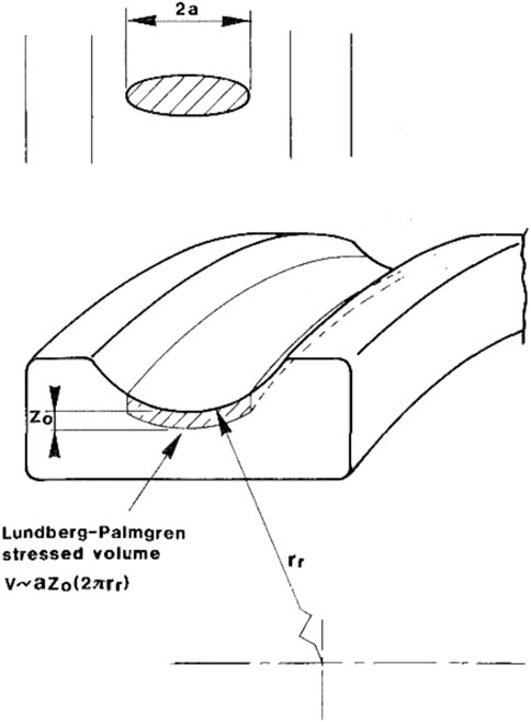
FIGURE 1. Risk volume of a deep groove ball bearing during rotating operations of rolling bearings suggested by Lundberg and Palmgren (Lundberg and Palmgren, 1947) (taken from (Ioannides and Harris, 1985)).
The correction factor of ALP, as well as the parameters of e, c, h depend on the material, which can be determined experimentally. Although the stress state below the rolling contact is multiaxial, the bearing fatigue lifetime calculated using the maximum orthogonal shear stress shows good agreement with the experimental results of the full-scale bearings subjected to constant external loads in rotating applications. The theory of Lundberg-Palmgren was extended by Ioannides and Harris (Ioannides and Harris, 1985) to accommodate the material property concerning the subsurface stress distribution below the rolling contact and the fatigue limit stress σu as a function of material conditions:
with the step function H(x):
The depth of the fatigue, which corresponds to the position of the crack initiation, is replaced by introducing the stress-weighted factor z′ since the distribution of subsurface stress below the rolling contact is considered. According to the Lundberg-Palmgren theory (Lundberg and Palmgren, 1952), the orthogonal shear stress is preferred to be concerned for evaluating the subsurface stress state of rolling contacts with respect to the risk volume under the bearing raceway accompanied by material alterations due to alternating shear stresses (Voskamp, 1997). Harris and Kotzalas (Harris and Kotzalas, 2006) mentioned that the subsurface stress state can also be assessed according to the distortion energy criterion accompanied by the range of the material alteration below the rolling contact. The distortion energy criterion assumes that the yield of ductile materials occurs when the maximum distortion strain energy exceeds a certain shear stress level. From the classical fracture mechanic point of view, plastic deformations of steel materials are caused only by the deviatoric stress components, which lead to a shape change of a loaded body. It is generally believed that the hydrostatic stress component obtained from the average of the three principal stresses induces only the volumetric change. Hence, the stress deviator of the first stress invariant J1 is equal to zero, which means that the influence of the hydrostatic stress state is completely neglected:
where σ1, σ2, and σ3 are the principal stresses. Since the distortion energy by loading must be larger than zero, stress components of a loaded volume element can be expressed as a positive scalar value representing the von Mises equivalent stress σVM. According to the von Mises theory, the equivalent stress state is found on oblique planes, which is defined by the angle between the normal stress vectors (normal to the plane) and the principal axes. The stress vector always has the same angle in all three principal axes. In this case, the yielding can be described by the maximum of the shear stresses on this octahedral plane:
The octahedral shear stress criterion is used in classical fracture mechanics since fatigue behavior for ductile materials is mainly determined in uniaxial loading. Fatigue behavior of metallic materials is derived from an S-N curve (known as Wöhler curve) determined by applying cyclic load with constant amplitude such as tension-compression, rotating-bending or alternating torsion, which are standardized in DIN 52100 and ISO 1099. The S-N curve proposed by Wöhler (Wöhler, 1863) was a single log-scale plot of the cycle number to failure depending on load amplitudes. Later, the fatigue test results were suggested by Basquin (Basquin, 1910) to be plotted in a double logarithmic scale, in which the test results can be simplified as a linear approximation (called the Basquin line), as shown in Figure 2.
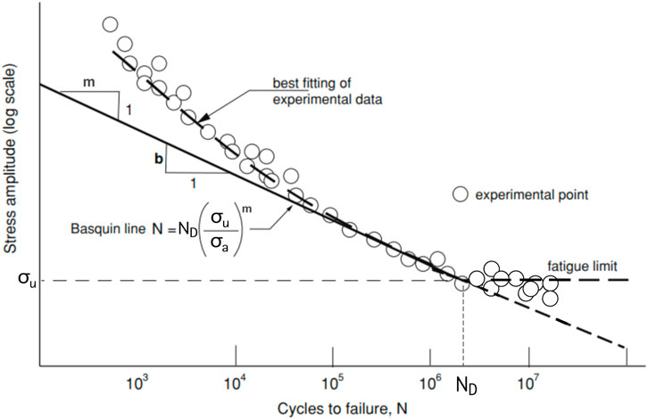
FIGURE 2. S-N Curve regarding to the Basquin theory with the slope m from (Milella, 2012); σu - fatigue limit stress.
According to the work of Basquin, the relationship of the experimental results to the simplified straight Basquin line is expressed as:
where m is the slope of the Basquin line. The standard regression error is used to calculate the statistical scatter of fatigue life which may be affected by many factors such as test environment, specimen conditions, and residual stresses. In general for metallic materials, the S-N curve is represented by the static strength Rm, endurance limit σf, and the corresponding edge number of cycles ND. In the HCF region of rolling bearings, the endurance limit is known as the fatigue limit stress σu, as shown in Eq. 2. Below the fatigue limit stress value, the material should undergo infinite load cycles without fatigue failure (Ioannides and Harris, 1985). For various load amplitudes, Miner tried to apply the hypothesis of Palmgren (Palmgren, 1924) mathematically, in which the risk of damages caused by different load amplitudes will be accumulated linearly with respect to energy absorption in the loaded volume (Miner, 1945):
where n denotes the number of applied load cycles for the number of applied loads i. The ratio between the applied load cycles and the corresponding number of cycles to failure is considered individually as the partial risk of damages d. The material failure is assumed to occur if the sum of the partial damages reaches a certain limit value. According to the Palmgren-Miner linear damage rule, the yielding will occur, when:
where kPM is the limit risk value that was originally chosen as 1 for the aircraft skin material made of aluminium alloy (Miner, 1945). However, as this theory becomes more widespread, it is argued that this limit value may vary depending on the materials (Walla et al., 1990). According to the Palmgern-Miner theory, the maximum number of cycles to failure Np can be expressed by the ratio of the collective load cycles of all given stress levels to the sum of damage risks:
where the index p denotes the probability of failure in this study. The Palmgren-Miner theory is adopted in ISO 281 to take into account the rotational operating conditions of a rolling bearing subjected to various external load magnitudes when evaluating the fatigue life of rolling bearings. Due to the geometrical nature of the rolling bearings, an internal load history appears even at a constant load amplitude. In this study, this will be referred to as the internal dynamic behavior of rolling bearings, which should depend on the bearing operating conditions and load types. The novel approach proposed in this study is based on the Palmgren-Miner theory, where the use of the S-N curve is required to individually evaluate the subsurface stress state below rolling contacts during rotating operations. The geometrical characteristic of rolling bearings is represented by the internal dynamic behavior accompanied by the external load type, which acts as the most important factor in evaluating the internal stress cycle of the rotating rolling bearing in this proposed approach. The proposed approach will be applied to two types of rolling bearings: cylindrical roller bearing NU 1006 (CRB NU 1006) with line contact and angular contact ball bearing 7208 B-XL-TVP (ACBB 7208) with point contact to evaluate the suitability of the new approach proposed in the present paper. A schematic of both contact types is shown in Figure 3.
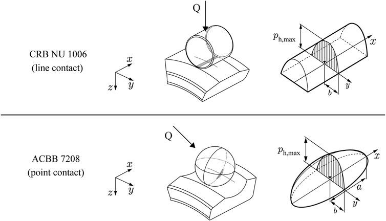
FIGURE 3. Schematic of contact pressure distribution on the contact area depending on contact types; CRB NU 1006 with line contact and ACBB 7208 with point (elliptical) contact.
2 Internal dynamic behavior of rolling bearings
Consider that the inner ring of a rolling bearing is mounted on a rigid shaft rotating with an angular velocity of ωic and the outer ring is rotating with an angular velocity of ωoc. The rolling element rotates about the bearing axis with an angular velocity of ωre, while simultaneously rotating about its own axis with an angular velocity of ωb, as shown in Figure 4.
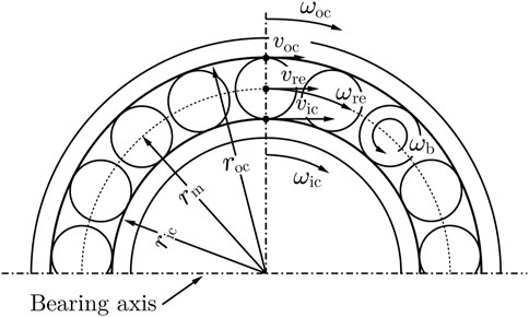
FIGURE 4. General observation of kinematics in rolling bearings.
Assuming that:
• Effects of inertial forces and centrifugal forces are neglected.
• Contact angle α is identical at the inner and outer ring.
• Pure rolling occurs without sliding between the rolling element and the raceways.
• Deflections at the rolling contact are small enough compared to the contact bodies to be ignored.
The speeds of the inner and outer contact are expressed as:
where ric and roc are the distance of the inner and outer contact from the bearing axis, respectively. The pitch diameter is denoted by dm. Hence, the speed of the rolling element rotating about the bearing axis in the circumferential direction is obtained from:
For the fixed outer ring, the speed of the rolling element is equal to half the speed of the inner ring. Assuming the position of the first rolling element is placed at Φssv = 0° as shown in Figure 5, and the maximum rolling element force appears at the first rolling contact.
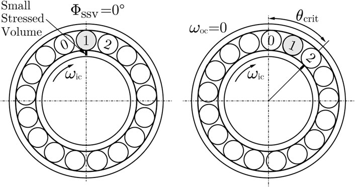
FIGURE 5. Change of the position of the small stressed volume of the bearing inner ring due to the internal dynamic behavior during rotating operation; CRB NU 1006.
Note that the rolling contact refers to the contact between the inner ring, the rolling element and the outer ring. The number of rolling contacts that actually load the volume of the bearing rings depends on the radial force, which indicates the load distribution factor ϵ. In this study, this volume is called the small stressed volume (SSV), which corresponds to the rolling contact position. From the Palmgren-Miner theory’s point of view, it is assumed that each absorbed energy induced by various loads is accumulated in one volume element. Therefore, it may be sufficient to use the damage accumulation theory by considering only the SSV loaded by rolling element forces. If the inner ring continues to rotate, the second rolling contact occurs at the critical angle:
with
where Z is the number of rolling elements, and the plus sign is indicated for the inner ring and the minus sign for the outer ring. Due to the difference in the rotating speeds between the inner ring and the rolling element, the SSV is subjected to the rolling element force induced by the second rolling element at Φssv = θcrit. After one first complete revolution of the inner ring (or the SSV), the position of the rolling element closest to the initial angle of Φssv = 0° is displaced by a certain distance from it. The displacement of the rolling contact changes with each revolution and the maximum rolling element force occurs again after a certain number of inner ring revolutions, depending on the bearing geometry. The number of rolling contacts up to this point can be counted regardless of external forces and defines the internal stress cycle of the rolling bearing due to the internal dynamic behavior. Figure 6 shows the displacement of the rolling contact position as a function of the number of inner ring revolutions for the example bearings.
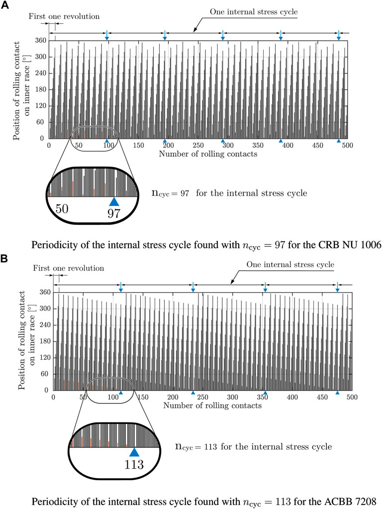
FIGURE 6. Periodicity of the internal stress cycle due to the displacement of the rolling contact position corresponding the SSV position. (A) CRB NU 1006 (B) ACBB 7208.
The length of each bar represents the angular distance of the SSV from the initial angle of Φssv = 0° for each rolling contact. For the CRB NU 1006, the periodicity is found with the 97 rolling contacts, where the first position of the rolling contact returns to the initial position at Φssv = 0°, see Figure 4A. In the case of the ACBB 7208, the rolling contact position returns to the initial position after the first 113 rolling contacts, which are repeated continuously, as shown in Figure 4B The mean number of rolling contacts during one revolution of bearing rings associated with the SSV is expressed for the rotating inner ring with the fixed outer ring as:
and for the rotating outer ring with the fixed inner ring as:
3 Proposal a new approach
3.1 Based on the existing theories in rolling bearings
The calculation model suggested by Lundberg and Palmgren is mainly based on the experiment results from full-scale bearing fatigue tests (Lundberg and Palmgren, 1947), (Lundberg and Palmgren, 1952). Based on the work of Zaretsky et al. (1996), the fatigue life N of rolling bearings in the Lundberg-Palmgren theory is inversely proportional to the maximum contact pressure pmax at rolling contacts:
where the exponent nexp is expressed for point contact as:
and for line contact as:
the stress criterion exponent c, which is related to the Wöhler tests, and the exponent h, which is related to the corresponding depth of the maximum orthogonal shear stress, are determined experimentally. The slope of the Weibull distribution e was approximated as 10/9 for point contact and as 3/2 for line contact from the full-scale fatigue tests of the rolling bearings made of bearing steel 52100 (see Figure 7), where the exponent c is suggested for 31/3 and the exponent h for 7/3 based on the Hertzian theory.
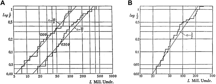
FIGURE 7. Weibull slope from the full-scale fatigue test results (A) bearing type of SKF 1309 and SKF 6309 (point contact); (B) bearing type of SKF I-37906 (line contact) (Lundberg and Palmgren, 1947).
Later, the value of e for line contact was corrected to 9/8 by Lundberg and Palmgren. They pointed out that the applied external load P is proportional to the maximum contact pressure:
where the exponent pexp is known as the bearing life factor. According to the theory of Lundberg and Palmgren, the exponent pexp for point contact is given by:
and for line contact by:
Consequently, the bearing life exponent pexp is proposed pexp,point = 3 for point contact and pexp,line = 10/3 for line contact, which is still used in the standard calculation model of ISO 281. Note that only the maximum value of orthogonal shear stresses in the rolling contact is considered as a criterion for their calculation model due to the proportionality to the given external load. Furthermore, the probability of failure is taken into account according to the Weibull weakest link theory (Weibull, 1939; Weibull, 1951). In 1985, the calculation model of Lundberg and Palmgren was extended by Ioannides and Harris (1985) introducing the two key factors. They proposed the occurrence of the bearing fatigue by considering the distribution of subsurface stresses near the Hertzian contact areas, which should be assessed with the fatigue limit stress σu as a function of the material property. In addition, instead of the depth of the maximum orthogonal shear stress, the evaluation of the subsurface stress distribution is estimated by the stress weighted average depth factor z′. The experiments of Lundberg and Palmgren were carried out under ideal test conditions such as constant external loads for rotating operations. Later, the Ioannides-Harris calculation model is extended by adopting the Dang Van fatigue criterion in 1999 (Ioannides et al., 1999). This criterion is also used in previous studies (Coors et al., 2019). To take the influence of varying external loads into account, they used the Palmgren-Miner linear damage rule in their calculation model by considering the time ratio of each given different load magnitude. In the works of Morales-Espejel et al. (2015), Morales-Espejel and Gabelli (2019), an overall model for rolling bearings based on the Palmgren-Miner damager rule is proposed. They suggested the evaluation of the subsurface stress distribution below the rolling contact according to the Dang Van criterion. Damage risk of each cycle from this is accumulated linearly according to the Palmgren-Miner theory, which affects the sliding and wear model based on the Archard wear model (Archard, 1953). Their works provided a lot of inspiration for this study. The main concept of the proposed approach in this paper is that all rolling contacts, which occur during rotating operations, will be considered based on the Palmgren-Miner linear damage rule to consider the internal dynamic behavior accompanying various external load magnitudes.
3.2 General procedure
In this section, the new approach is applied to both example rolling bearings—CRB NU 1006 as well as ACBB 7208 to calculate the bearing fatigue life. Figure 8 introduces a general procedure of the proposed approach for rotating applications.

FIGURE 8. General procedure of the proposed approach to predict fatigue life in rolling bearings.
Step 1. Determination of repeated internal stress cycleFirst of all, it is to examine whether the rolling bearing exhibits an internal stress cycle and its repetition to apply the damage accumulation theory. In general, the internal dynamic behavior related to the internal stress cycle is inferred as a general phenomenon of rolling bearings, as shown in Figure 6. All rolling contacts and their corresponding angular distances from the initial position of Φssv = 0° can be found in relation to the critical angle θcrit, the value of which is determined separately for a rotating inner ring and a rotating outer ring. The internal stress cycle depends on the bearing geometry such as the radius of the inner and outer contact, the pitch diameter and the diameter of the rolling element. Thus, the internal stress cycle may indicate the type and characteristics of rolling bearings.
Step 2. Determination of load distributionLoad distribution in the statically loaded rolling bearing is calculated for given external loads. In this study, the calculation models are chosen as the standard calculation approaches, which are recommended by DIN 26 281. The layer model is used for roller bearings and the 3-DOF calculation model for ball bearings. Since the load distribution does not depend on the position of the rolling elements, the rolling element force Q for all rolling contact positions determined in Step 1 may be obtained by interpolating the calculated load distribution.
Step 3. Determination of the rolling contacts based on the Hertzian theoryThe calculation of the rolling contact relating to the contact area and the contact pressure is carried out according to the Hertzian contact theory (Hertz, 1882). It is recommended to use the approximated equations proposed by Brew and Hamrock (Brewe and Hamrock, 1977) since all rolling contact must be considered depending on the load distribution. According to the Hertzian theory, the contact deflection δ and the major semi-axis a as well as the minor semi-axis b of the elliptical contact can be obtained by:
where ∑ρ is the sum of the curvature of the contact bodies, Ered is the reduced elastic modulus assuming both contact bodies made of the same material. According to the Brew and Hamrock approximation, the elliptical ratio κ, the elliptical integrals
with
where r1x and r2x are the radius of the contact body 1 and 2 on the yz-plane, r1y and r2y on the xz-plane, respectively. According to the Hertzian theory, the contact pressure at any point in the contact area can be determined using the following equations for elliptical contact:
with
For the case of line contact, it is generally assumed that the major semi-axis a is constant for the effective contact length of the rolling element leff. Thus, the distribution of the contact pressure for line contact is expressed as:
with
These equations are used to effectively solve the Hertzian contact problem in rolling bearings with minimal errors (Bader, 2018).
Step 4. Determination of the distribution of subsurface stresses using an elastic half-space modelThe distribution of the subsurface stress based on the Hertzian contact obtained in Step 3 is determined using an elastic half-space model rather than using the finite element method because of the computation time and efficiency. Note that all rolling contacts must be considered in this proposed approach. In this study, the approach proposed by Johnson (Johnson, 1985) is recommended for line contact, and the approach proposed by Sackfield and Hills (Sackfield and Hills, 1983) for elliptical contact. In the calculation, the half-space model is divided into 300 elements in the rolling direction for the distance of 60 mm, and into 200 elements in the depth for the distance of 40 mm from the contact area to the core of the ring. As a result, the half-space model consists of 300 by 200 elements, where the size of one element corresponds to 0.002 mm by 0.002 mm. Note that the interval of the depth of the half-space model plays an important role in this proposed approach because the damage risk is evaluated along the depth for each z-layer separately. Therefore, the interval of the half-space model in the depth direction should be small enough.
Step 5. : Calculation of damage risk using the S-N curveTo consider the Lundberg-Palmgren theory, orthogonal shear stress is adopted in this proposed approach as the fatigue criterion. The stress value along the y-axis in the rolling direction is referred to as a z-layer. The half-space model used in Step 4 consists of 200 elements over 40 mm, resulting in a total of two hundred z-layers, as shown in Figure 9.Each layer for the rolling contact is assessed with the difference between the maximum and minimum of the orthogonal stresses, which enables an evaluation of the subsurface stresses that vary due to other influences such as friction on the contact surface. This calculation is carried out for all rolling contacts that occur during the internal stress cycle:
where the index i denotes the number of the rolling contacts ncyc for one internal stress cycle, and the index j is the number of the z-layers, respectively. In this study, it is assumed that the subsurface stress distribution obtained statically using the half-space model in Step 4 represents the state of the subsurface stress during the rolling contact with time. This is based on the assumption that the stress value at the beginning and the end of the rolling during the rolling contact can be neglected due to the occurrence of very small damage risks in comparison to the maximum damage risk at this rolling contact in terms of the fatigue limit stress of the bearing steel. In this way, the time dependence of the subsurface stress in the rolling contact can be replaced by the number of rolling contacts. In addition, the depth parameters such as z, z′ and h in the existing calculation models are replaced by evaluating the subsurface stress along the depth.
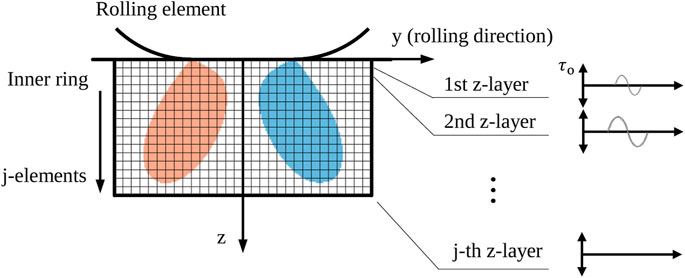
FIGURE 9. Elastic half-space model used in this approach to determine the distribution of subsurface stresses below the rolling contact; each z-layer is evaluated along the depth with the fatigue criterion.
Step 6. Determination of the load cycle to failure based on the Palmgren-Miner theoryThe difference in the orthogonal shear stresses for the z-layer refers to the stress amplitude. Damage risk to failure for each rolling contact is determined as partial damage risk using an S-N curve based on Equation 7. To avoid any theoretical conflict by using the orthogonal shear stress as the fatigue criterion, the S-N curve is chosen for the bearing steel AISI 52100, which is determined in completely reversed torsional fatigue tests (Styri, 1951) in Figure 10.Based on this S-N curve, a slope of m = 10.1 for the 10% probability of failure, and the fatigue limit stress of about 380 MPa with the corresponding edge cycle number of about 108 are approximated to use for this proposed approach. Thus, the Basquin equation can be modified for this approach as:
The partial damage risk of each z-layer will be accumulated linearly for the rolling contact ncyc during one internal stress cycle according to the Palmgren-Miner theory using Eq. 10. Consequently, the minimum value of calculated load cycles along all z-layer will correspond to the fatigue life of the rolling bearing:
In this approach, the probability of failure of bearing fatigue life is presumed to correspond to the probability of failure of the S-N curve used. This means the 10% probability of failure is taken from the slope of the S-N curve, because only the SSV that is repeatedly loaded due to the rolling contacts must be evaluated by using the Palmgren-Miner theory, taking the individual rolling contacts into account. In this way, the Weibull exponent e is replaced by using the S-N curve directly. At the location, where the minimum load cycle appears, a macrocrack is presumed to form with a certain physical length in terms of crack initiations.
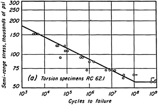
FIGURE 10. S-N curve of the bearing steel AISI 52100 in completely reversed torsional fatigue (Styri, 1951).
3.3 The simple link concept—Consideration of residual stresses
Since the proposed approach is based on the Palmgren-Miner linear damage rule, the influence of residual stresses is not taken into account analytically. However, since the calculation of the new approach is performed based on the subsurface stress distribution, the residual stress can be applied. For this purpose, the measured residual stress σrs must be available. According to Melan’s theorem (Melan, 1936), the stress state remains constant in time after certain load cycles, independent of the applied loading. This general phenomenon is associated with material cyclic hardening behavior (Dang Van et al., 1982), (Voskamp, 1997). At this time, the stress state accompanied by residual stresses is the saturation state. Hence, the residual stress σrs maybe added to the initial stress state σini, which is caused by the applied load:
this may represent the stress state related to the hydrostatic and deviatoric stress components. According to the theory of Mohr (1914), the principal stresses of the total stress state σtot can be obtained by:
Since the stress state can be expressed by the von Mises equivalent stress, the three principal stresses can be used to determine the von Mises equivalent stress, which may denote the resulting stress state. By applying Eqs 41–43 in Eq. 4, the von Mises equivalent stress of the resulting stress state σtot,VM can be obtained, which may reflect the total stress state considering the residual stress. The von Mises equivalent stress of the resulting stress state can be expressed as a new stress tensor matrix τnew relating to orthogonal shear stresses using the ratios to the maximum contact pressure. For line contact, it was analytically observed that the ratio of the von Mises equivalent stress to the maximum contact pressure is about 0.57, and the ratio of the orthogonal shear stress to the maximum contact pressure is about 0.25. Assuming that the fatigue life must be the same for a given load regardless of whether the stress state is evaluated by using the von Mises equivalent stress or orthogonal shear stress, the following relationship between both stresses may be included in the new stress state for line contact:
This relationship must be valid for the maximum value for line contact. However, this simple link concept may also be applicable to all stress states.
4 Comparison of calculation results
The material property of both example bearings (CRB NU 1006 and ACBB 7208) is presumed to be made of the same hardened bearing steel of 100Cr6 (AISI 52100), which can be found in Table 1.
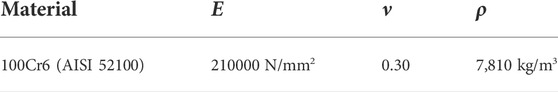
TABLE 1. Material property of bearing steels used in this study.
For all calculations of both example bearings, it is assumed, that the inner ring rotates at about 3,000 rpm, and the outer ring is stationary, in full-flooded lubrication.
4.1 The cylindrical roller bearing—CRB NU 1006 (FAG)
The load distributions of the example bearings are calculated according to DIN 26 281. For the CRB NU 1006, the layer model recommended for cylindrical roller bearings in DIN 26 281 is used, where the profile of the roller is approximated by an ideal logarithmic profile. The calculation of the load distribution in the statically loaded CRB NU 1006 subjected to pure radial loads is performed without tilting moment force, which can simplify the use of the proposed approach regarding the position of the maximum contact pressure on the raceway. This is because the maximum contact pressure of all rolling contacts can be assumed always to appear in the middle of the raceway during the rotating operation regardless of the magnitude of rolling element forces. Hence, it should be sufficient that the evaluation of the subsurface stresses is carried out at this location. The subsurface stress is determined according to Johnson’s approach as recommended. The calculation of fatigue life of the CRB NU 1006 is performed according to ISO 281 as well as according to the proposed approach, for the maximum contact pressure of 2.54 GPa (C/P = 3.67), 3.00 GPa (2.3), 3.45 GPa (1.7), and 3.80 GPa (1.3). The residual stresses measured for the maximum contact pressure of 2.54 and 3.80 GPa are taken into account according to the simple link concept proposed in this study. The calculation results are compared to B10, which is obtained from the full-scale fatigue tests, as a function of the maximum contact pressure on the inner ring in Figure 11.
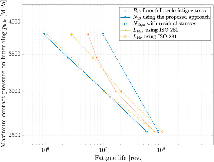
FIGURE 11. Calculated fatigue life of the CRB NU 1006 as a function of the maximum contact pressure on the inner ring caused by pure radial loads in comparison with the experimental results B10 provided by FVA 866-I.
The modified rating life L10m and the nominal-reference life L10r are compared to the test results B10. In this study, the nominal reference life is more conservative than the modified rating life. Nevertheless, the good agreement with the experimental results can confirm again that ISO 281 is a suitable method for predicting the fatigue life of rotating bearings for constant external loads. The calculation results N10 obtained by using the proposed approach show a good agreement with the nominal-reference life L10r according to ISO 281. In addition, both results show the same tendency that the deviation of the calculation results to the test results becomes larger by increasing the maximum contact pressure (i.e. increasing the external load). However, it can be seen that this tendency is reduced when the residual stress is considered. Due to the residual stress, the fatigue life for ph, max of 2.54 GPa is increased by 1.58 times, and the fatigue life for ph, max of 3.80 GPa by 10.5 times. These results confirm a similar trend with studies on the effect of residual stresses on the fatigue life of rolling bearings (Pape et al., 2020). Compare to the test results B10, the simple link concept seems to overestimate the influence of the residual stress, at least for high load magnitudes because of the relationship between the maximum orthogonal shear stress and the von Mises equivalent stress, which may be valid only for the maximum value in the absence of residual stresses. Concerning these results, if the simple connection concept is further studied and the residual stress is properly considered, a more accurate life expectancy prediction can be expected.
4.2 The angular contact ball bearing—ACBB 7208-B-XL-TVP (FAG)
The load distribution in the statically loaded ACBB 7208 subjected to pure axial loads is performed according to the 3 DOF model recommended also in DIN 26 281. The contact angle is presumed to be the same for the inner and outer contact by using this model. In cases of combined loads, each rolling contact has a different contact angle, which determines the position of the maximum contact pressure for rolling contacts accordingly. Thus, the distribution of the subsurface stresses in the material below all rolling contacts must be considered for combined load cases. For this purpose, the approach of Sackfield and Hills is used to determine the distribution of subsurface stresses. Furthermore, this approach is more suitable for the elliptical contact area due to the consideration of the elliptical ratio. The calculation of fatigue life of the ACBB 7208 is carried out according to ISO 281 as well as the proposed approach, for the maximum contact pressure of 2.46 GPa (C/P = 3.2), 2.64 GPa (2.5), 2.80 GPa (2.1), 2.94 GPa (1.8), and 3.04 GPa (1.6). Figure 12 shows the calculation results as a function of the maximum contact pressure on the inner ring.
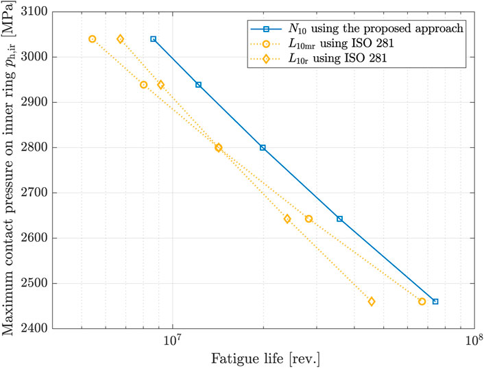
FIGURE 12. Calculated fatigue life of the ACBB 7208 as a function of the maximum contact pressure on the inner ring caused by pure axial loads.
The modified-reference life L10mr and the nominal-reference life L10r are relatively conservative compared to the calculation results obtained by using the proposed approach. As mentioned before, the fatigue life according to ISO 281 is generally less than the experimental results. Therefore, it can be argued that the proposed approach provides an adequate range of fatigue life of the ACBB 7208 for rotating operation.
4.3 Extention of the proposed calculation model for oscillating application
The proposed approach is based on the Palmgren-Miner linear damage rule to predict the lifetime of rolling bearings when exposed to various external loads and under oscillation operation by individually considering the subsurface stress distribution. This means that the determination of the fatigue life is performed by considering the number of rolling contacts experienced by the loaded volume, i.e the SSV. Based on this perspective, the proposed approach is extended for oscillating applications by introducing the ratio of the rolling contact numbers between rotation and oscillation:
where nmean is the mean number of the rolling contact during rotating operation, nosc represents the number of rolling contacts that occur during oscillating operation. The mean number of rolling contacts can be obtained from Eq. (16) for the rotating inner ring with the fixed outer ring, and Eq. 17 for the rotating outer ring with the fixed inner ring. Considering the critical angle θcrit of 44.62° obtained from Eq. 14 for the inner ring of the ACBB 7208, only one rolling contact will occur if the rolling bearing oscillates at the double amplitude of 40°. The mean number of rolling contacts on the inner raceway nmean, ir is calculated as 8.0673 per revolution. Thus, the oscillating fatigue life with the given double oscillation amplitude can be obtained by:
At the Institute of Machine Design and Tribology, full-scale bearing fatigue tests of the ACBB 7208 for oscillating operation are performed within the HBDV project funded by BMWK (Grant number: 01183488/1). The rolling bearing oscillates with a constant double oscillation amplitude of 40° while a constant pure axial load is applied resulting in the maximum contact pressure of about 3.0 GPa on the inner ring. The tests are still running over 120 million oscillations, and no fatigue is observed yet. Considering the 10% probability of failure, an oscillation number of about over 200 million oscillations can be expected for 50% probability of failure approximately. This value may become larger if the influence of residual stress is considered regarding the high contact pressure. In order to obtain a comprehensive probability of failure for the fatigue life, a considerable amount of time must be required. Note that this extended equation is examined only for cases of the oscillating angular contact ball bearings subjected to a constant axial load with a constant oscillation amplitude.
5 Summary and discussion
In this study, a new approach was proposed to predict the bearing fatigue life. This approach allows to advance the operating conditions with respect to the bearing fatigue life and thus to improve their application. The proposed approach is based on the Palmgren-Miner linear damage rule, and the distribution of subsurface stresses is evaluated using the S-N curve, adopting the orthogonal shear stress as the fatigue criterion suggested by Lundberg and Palmgren. The material property that Ioannides and Harris considered by introducing the fatigue limit stress and the stress weighted factor is directly taken into account from the S-N curve. The probability of failure of the S-N curve is suggested to be used for the probability of failure of the bearing fatigue life since only the loaded volume SSV is considered. However, the S-N curve may not represent exactly the probability of failure because it depends on many factors such as residual stress, shape and size of specimens, load types, and operating conditions. In terms of the fatigue criterion, an S-N curve determined in repeated torsion or compression-bending should be used, in which the stress state is similar to that below rolling contact. Consequently, the proposed approach depends mainly on the S-N curve relating to the life exponent c. The Weibull exponent e, as well as the factors z, z′, h are not included in this new approach. The proposed approach is evaluated mainly by considering the number of rolling contacts. Due to the internal dynamic behavior of rolling bearings, which may refer to as a common phenomenon, the occurrence of the internal stress cycle can be found depending on the geometry of rolling bearings. Geometric bearing property is presumed to represent the internal stress cycle. All rolling contacts during the rotating operation are assessed individually to consider various external loads. To predict the oscillating fatigue life of rolling bearings, the proposed approach was extended by introducing the number of rolling contacts, which appears during the oscillating operation. The simple link concept was introduced to consider the influence of residual stress since the distribution of subsurface stresses is evaluated in this proposed approach. The simple link concept is based on the ratio of the maximum contact pressure to the von Mises equivalent stress as well as to the maximum orthogonal shear stress. Considering the residual stress in this way, the orthogonal shear stress can be used. EHD property is not yet included in this approach, which can be taken into account further by introducing a sliding wear model. By further studying the proposed approach, it can be expected that subsurface stress and stress state at the contact surface can be considered simultaneously.
Data availability statement
The original contributions presented in the study are included in the article/supplementary material, further inquiries can be directed to the corresponding author.
Author contributions
J-IH wrote this article, designed and performed the calculations, and analysed the results. GP supervised the present work, discussed the basic design of the proposed model and provided suggestions for the final discussion.
Funding
This research was funded by Federal Ministry for Economic Affairs and Climate Action (BMWK, Bundesministerium für Wirtschaft und Klimaschutz) with the grant number of 01183488/1.
Acknowledgments
The results presented in this paper were obtained within the project of Design of Highly Loaded Slewing Bearings (HBDV, Auslegung hochbelasteter Drehverbindungen). The authors would like to thank the German Federal Ministry for Economic Affairs and Climate Action (BMWK, Bundesministerium für Wirtschaft und Klimaschutz) for the financial and organizational support of this project. In addition, the authors are also deeply grateful to the German Federation of Industrial Cooperative Research Associations (AiF, Arbeitsgemeinschaft industrieller Forschungsvereinigungen) for providing the experimental results obtained within the project of FVA 866 I - Einfluss kurzfristiger Überlasten auf die Lebensdauer von Wälzlagern (Grant number: 20733 N).
Conflict of interest
The authors declare that the research was conducted in the absence of any commercial or financial relationships that could be construed as a potential conflict of interest.
Publisher’s note
All claims expressed in this article are solely those of the authors and do not necessarily represent those of their affiliated organizations, or those of the publisher, the editors and the reviewers. Any product that may be evaluated in this article, or claim that may be made by its manufacturer, is not guaranteed or endorsed by the publisher.
References
Archard, J. F. (1953). Contact and rubbing of flat surfaces. J. Appl. Phys. 24, 981–988. doi:10.1063/1.1721448
Bader, N. (2018). Traction in EHL-Contacts - the influence of local fluid rheology and temperatures. Hannover, Germany: Ph.D. thesis, Gottfried Wilhelm Leibniz University.
Basquin, O. H. (1910). The exponential law of endurance tests. Proceedings-American Soc. Test. Mater. 10, 625–630.
Brewe, D. E., and Hamrock, B. J. (1977). Simplified solution for elliptical-contact deformation between two elastic solids. J. Lubr. Technol. 99, 485–487. doi:10.1115/1.3453245
Coors, T., Hwang, J. I., Pape, P., and Poll, G. (2019). “Theoretical investigations on the fatigue behavior of a tailored forming steel-aluminium bearing component,” in AIP Conference Proceedings (American Institute of Physics Publishing LLC), 4–20.2113
Dang Van, K., Griveau, B., and Message, O. (1982). On a new multiaxial fatigue limit criterion - theory and application. Biaxial multiaxial fatigue (EFG 3, 479–496.
Harris, T. A., and Kotzalas, M. N. (2006). Rolling bearing analysis. Boca Raton, London, New York: CRC Press Taylor & Francis Group.Essential concepts of bearing Technology
Hertz, H. (1882). Über die Berührung fester elastische Körper und über die Härte. Verhandlungen des Vereins zur Beförderung des Gewerbefleisses. Leipzig.
Ioannides, E., Bergling, G., and Gabelli, A. (1999). An analytical formulation for the life of rolling bearings. Acta Polytech. Scand. Mech. Eng. Ser.
Ioannides, E., and Harris, T. A. (1985). A new fatigue life model for rolling bearings. J. Tribol. 107, 367–377. doi:10.1115/1.3261081
Lundberg, G., and Palmgren, A. (1947). Dynamic capacity of rolling bearings. Acra Polytech. Mech. Eng. Ser. 1, 7. doi:10.1115/1.4009930
Lundberg, G., and Palmgren, A. (1952). Dynamic capacity of rolling bearings. J. Appl. Mech. 16 (2), 165–172. doi:10.1115/1.4009930
Melan, E. (1936). Theorie statisch unbestimmter Systeme aus ideal-plastischem. Baustoff 145, 195–218.
Miller, K. J. (1984). “Initiation and growth rates of short fatigue cracks,” in Proc. IUTAM Symposium Eshelby Memorial Conference (Cambridge University Press), 477–500.
Miner, M. A. (1945). Cumulative damage in fatigue. J. Appl. Mech. 12, A159–A164. doi:10.1115/1.4009458
Mises, R. v. (1913). Mechanik der festen Körper im plastisch-deformablen Zustand. Nachrichten Ges. Wiss. Göttingen, Mathematisch-Physikalische Kl. 1913, 582–592.
Morales-Espejel, G. E., Gabelli, A., and de Vries, A. J. C. (2015). A model for rolling bearing life with surface and subsurface survival—Tribological effects. Tribol. Trans. 58, 894–906. doi:10.1080/10402004.2015.1025932
Morales-Espejel, G. E., and Gabelli, A. (2019). Rolling bearing seizure and sliding effects on fatigue life. Proc. Institution Mech. Eng. Part J J. Eng. Tribol. 233, 339–354. doi:10.1177/1350650118779174
Palmgren, A. (1924). Die Lebensdauer von Kugellagern (Life length of roller bearings or durability of ball bearings). Z. Des. Vereines Dtsch. Ingenieure (ZVDI) 14, 339–341.
Pape, F., Coors, T., and Poll, G. (2020). Studies on the influence of residual stresses on the fatigue life of rolling bearings in dependence on the production processes. Front. Mech. Eng. 6. doi:10.3389/fmech.2020.00056
Sackfield, A., and Hills, D. (1983). Some useful results in the classical hertz contact problem. J. Strain Analysis Eng. Des. 18, 101–105. doi:10.1243/03093247v182101
Styri, H. (1951). “Fatigue strength of ball bearing races and heat-treated 52100 steel specimens,” in Proceedings-American Society for Testing and Materials, 682.51
Tresca, H. E. (1864). Sur l’ecoulement des corps solides soumis a de fortes pressions. rue de Seine-Saint-Germain, 10, près l’Institut: Imprimerie de Gauthier-Villars, successeur de Mallet-Bachelier.
Voskamp, A. P. (1997). Microstructural changes during rolling contact fatigue: Metal fatigue in the subsurface region of deep groove ball bearing inner rings. Ph.D. thesis. Netherlands: Delft University of Technology.
Walla, J., Bommas, H., and Mayr, P. (1990). Schädigung von CK45N durch eine Schwingbeanspruchung mit veränderlichen Amplituden. HTM J. Heat Treat. Mater. 45, 30–37. doi:10.1515/htm-1990-450115
Weibull, W. (1951). A statistical distribution function of wide applicability. J. Appl. Mech. 18, 293–297. doi:10.1115/1.4010337
Weibull, W. (1939). A statistical theory of the strength of materials. Stockholm: Generalstabens litografiska anstalts förlag, 151.
Wöhler, A. (1863). Über die Versuche zur Ermittlung der Festigkeit von Achsen, welche in den Werkstätten der Niederschlesisch-Märkischen Eisenbahn zu Frankfurt a. d. O. angestellt sind. Z. für Bauwes. 13, 233–258.
Keywords: rolling bearing, RCF, rotating fatigue life, oscillating fatigue life, linear damage rule, orthogonal shear stress, residual stress
Citation: Hwang J-I and Poll G (2022) A new approach for the prediction of fatigue life in rolling bearings based on damage accumulation theory considering residual stresses. Front. Manuf. Technol. 2:1010759. doi: 10.3389/fmtec.2022.1010759
Received: 03 August 2022; Accepted: 09 September 2022;
Published: 07 October 2022.
Edited by:
Xincun Zhuang, Shanghai Jiao Tong University, ChinaCopyright © 2022 Hwang and Poll. This is an open-access article distributed under the terms of the Creative Commons Attribution License (CC BY). The use, distribution or reproduction in other forums is permitted, provided the original author(s) and the copyright owner(s) are credited and that the original publication in this journal is cited, in accordance with accepted academic practice. No use, distribution or reproduction is permitted which does not comply with these terms.
*Correspondence: Jae-Il Hwang, aHdhbmdAaW1rdC51bmktaGFubm92ZXIuZGU=