 Elie Amm1Melih Motro1Marc Fisher2Vlad Surdu2E. Brandon Strong2
 Jeffrey Potts3
 Christian El Amm3
 Suhair Maqusi3*
- 1Department of Orthodontics and Dentofacial Orthopedics, Henry Goldman School of Dental Medicine, Boston University, Boston, MA, United States
- 2Xironetic, Oklahoma, OK, United States
- 3Department of Surgery, Plastic and Reconstructive Surgery, University of Oklahoma, Oklahoma, OK, United States
Objective: To evaluate the precision of a computer vision (CV) and augmented reality (AR) pipeline for orthodontic applications, specifically in direct bonding and temporary anchorage device (TAD) placement, by quantifying system accuracy in six degrees of freedom (6DOF) pose estimation.
Methods: A custom keypoint detection model (YOLOv8n-pose) was trained using over 1.5 million synthetic images and a supplemental manually annotated dataset. Thirty anatomical landmarks were defined across maxillary and mandibular arches to maximize geometric reliability and visual detectability. The system was deployed on a Microsoft HoloLens 2 headset and tested using a fixed typodont setup at 55 cm. Pose estimation was performed in “camera space” using Perspective-n-Point (PnP) methods and transformed into “world space” via AR spatial tracking. Thirty-four poses were collected and analyzed. Errors in planar and depth estimation were modeled and experimentally measured.
Results: Rotational precision remained below 1°, while planar pose precision was sub-millimetric (X: 0.46 mm, Y: 0.30 mm), except for depth (Z), which showed a standard deviation of 5.01 mm. These findings aligned with theoretical predictions based on stereo vision and time-of-flight sensor limitations. Integration of headset and object pose led to increased Y-axis variability, possibly due to compounded spatial tracking error. Sub-pixel accuracy of keypoint detection was achieved, confirming high performance of the trained detector.
Conclusion: The proposed CV-AR system demonstrated high precision in planar pose estimation, enabling potential use in clinical orthodontics for tasks such as TAD placement and bracket positioning. Depth estimation remains the primary limitation, suggesting the need for sensor fusion or multi-angle views. The system supports real-time deployment on mobile platforms and serves as a foundational tool for further clinical validation and AR-guided procedures in dentistry.
Introduction
Computer vision (CV) technologies are transforming orthodontics by enhancing diagnostic and procedural precision (Olawade et al., 2025). These systems analyze radiographs, 3D scans, and photographs at levels beyond human consistency, improving detection of malocclusions and anatomical discrepancies (Olawade et al., 2025). Augmented reality (AR), powered by CV, has shown promise in clinical interventions—allowing accurate bracket placement (Lo et al., 2021) and more reliable insertion of temporary anchorage devices (TADs) compared to freehand techniques (Riad Deglow et al., 2023). These tools not only improve outcomes but also streamline workflows in clinical practice (Riad Deglow et al., 2023).
TADs offer critical anchorage for complex tooth movements and require high precision for success. Even slight misplacement can lead to complications such as root damage or reduced stability (3). AR-guided systems enable clinicians to superimpose digital templates on patient anatomy in real time, enhancing placement accuracy. Studies show that AR-assisted TAD insertion significantly reduces angular and positional deviations, with performance less dependent on operator experience (Riad Deglow et al., 2023).
This study aims to assess and characterize the precision of a Computer Vision pipeline for orthodontic applications (e.g., direct bonding and TAD placement), incorporating image acquisition, deep learning-based object detection, pose estimation, and AR visualization. We focus on quantifying cumulative system error and identifying which pipeline components most influence accuracy.
Materials and methods
Experimental design
The HoloLens 2 is launched and affixed to a fixed pedestal with known spatial coordinates. The headset was placed on a mannequin head, and its position guided by reference markings. A typodont (Tangshan Zhengtong Exhibition Co., Ltd., China) is affixed to a rigid base at a determined distance (55 cm) and a pose applied to the upper and lower arches separately: The typodont was left installed on its rigid base, and distance to headset camera measured using a ruler with 1 mm markings. A 30° yaw was applied to the typodont base, and an additional 25° pitch was applied to the upper arch using a 3D printed block. Roll was kept at zero to the reference frame.
We chose the experimental setup at 55 cm to represent the upper limit of “working distance” as informed by surgical loupe manufacturers (35–55 cm). Since accuracy of keypoint detection is expected to be inversely proportional to the distance to the sensor, this would represent the upper limit of the system’s internal precision.
Lighting condition: Headset-attached light source, color temperature 4500K, providing 200–220 Lux illumination (Urceri® SMT-912 Handheld light-meter).
Computer vision system
The requirements of the system include estimating the “6DOF” pose of the dental arches: Spatial position (3DOF: X,Y,Z) and orientation (3DOF: roll, pitch, yaw). The system should run on a mobile device, in real time, or near real time.
The pose estimation relies on “keypoint detection” from images of dental arches. For training the network, we selected known and easily identifiable landmarks to be used as keypoints for training the model (yolov8n-pose, Ultralytics®).
On the maxilla, eight keypoints were placed along the gingival margin from the right to left first premolars (capturing the anterior gumline curvature), together with four occlusal points at the canine and first premolar cusp tips and three interproximal incisor contact points (midline between central incisors and between each central and lateral incisor). The mandibular arch received an analogous set of eight gingival margin points, four cusp-tip points (canines and first premolars), and three incisor contact points, totaling 30 keypoints across both arches. If a tooth’s landmark was missing or obscured, an estimated anatomical position was used as a substitute to preserve the complete set (Rodríguez-Ortega et al., 2025). The landmarks used and an example of the models used for synthetic data generation are shown in figure 1 e.g. (Figures 1A–C). This landmark configuration was chosen to maximize visual detectability and anatomical relevance.
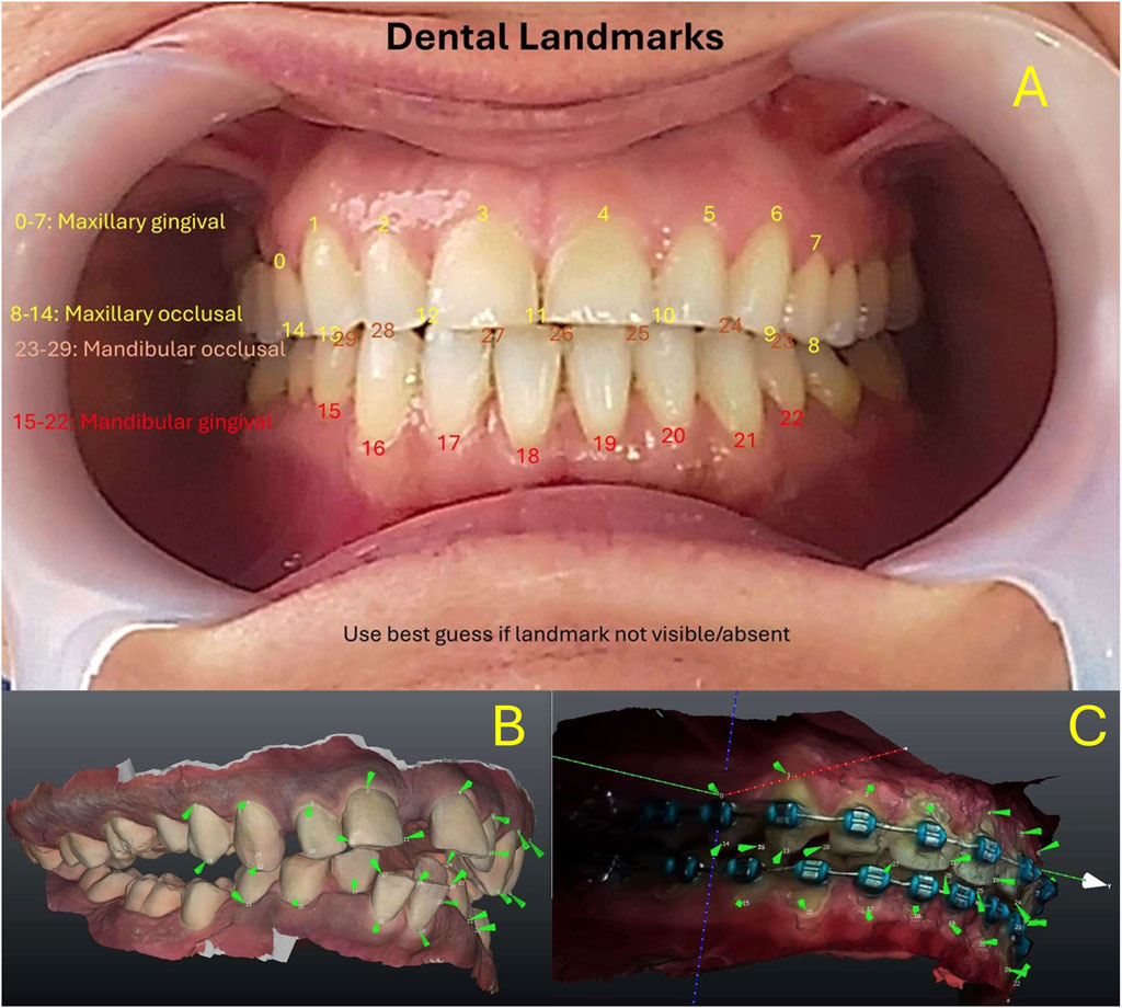
Figure 1. (A) Maxillary keypoints (0–14) and Mandibular Arch keypoints (15–29). (B) Keypoints reproduced on digital models for synthetic data generation. (C) Similar methodology used on bracketed dentition.
Knowing the spatial relationships between detected keypoints, the spatial pose of the arch is calculated “in camera space” (relative to the camera) using the Points-N-Perspective methods (PnP). The augmented reality system (HoloLens® 2, Microsoft Corp, Redmond, WA) then integrates this information into a “model” it has of the “world space”, accounts for head movements and gaze, and projects the required information to the user’s eyes, using stereoscopic principles to create the sense of depth. A diagram of the system architecture is shown in Figure 2.
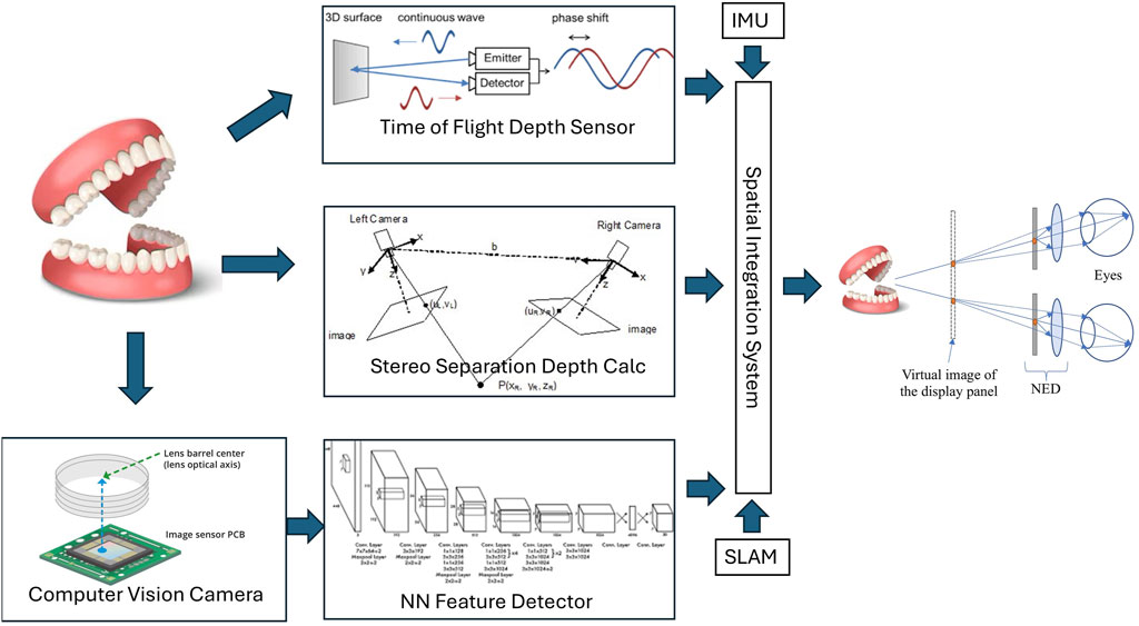
Figure 2. System Architecture overview. NN = Neural network. SLAM: Simultaneous Location and Mapping. IMU: Inertial Monitoring Unit. NED: Near-Eye Display.
Additional correction of depth estimates is provided by time-of-flight sensors and/or stereo-vision systems by leveraging HoloLens 2 built-in sensors.
The keypoint detector is based on custom-trained “State-of-the-art” vision detectors (Yolo-pose v8n and v11n, multi-class). We examined existing open source available keypoint (pose) detectors that could run on the HoloLens processor with reasonable performance. Yolov8n and Yolov11n, both from Ultralytics were selected. Alternative offerings focused on human pose and did not allow customization of the keypoint architecture, or ran on higher performance hardware. Yolov11 and yolov8 trained networks were found to perform equally well on detection, but run on different backends. Yolov11+Sentis performed slightly worse than yolov8+Barracuda on the HoloLens. Since the purpose of this paper is to examine the detection pipeline of a typical CV architecture, we did not perform further comparative work to identify the most performant detector architecture. Per the Ultralytics documentation, mAP and precision-recall curves are useful metrics for object “box” detection, less so for keypoint/pose detection. Ultralytics proposes KObj/Loss and PoseLoss as alternatives for pose detection, and those results are reported.
A custom synthetic dataset is generated using 100+ intra-oral scans of upper and lower arches, in a computer-generated system that simulates poses, lighting, and backgrounds. The dataset included an un-edited cohort of consecutive patients at presentation and follow-up, and covered a range of occlusion types, dental and periodontal pathologies, including randomly missing dentition at presentation. No patients were excluded. Missing teeth on intraoral scans were annotated by “best guess” using existing dentition, and labeled as “occluded”, as specified in the Yolov8 methodology. The synthetic training dataset was generated by projecting keypoints over synthetically generated images as described in Figure 1, using methodology similar to Tremblay et al. (2018). A manually annotated dataset of 1K images is used as a supplement. Still images were extracted from video capture of the HoloLens of dentitions. Annotation was done by 3 separate professionals with dental/orthodontic training. The annotators were instructed to follow the sequence of landmarks as described in Figure 1, and annotate only visible landmarks. Manual annotation is very labor intensive and did not result in significant improvement to NN performance, however, several authors have promoted mixed datasets containing synthetic and “real” training data. In total, 1.5M+ images are generated and used for training. Additionally, a separate dataset of 200K+ is created for a typodont detector. The specific details of training will be shared in a follow-up paper.
Training is done on an NVIDIA T4 equivalent GPU, with the large dental dataset (1.5M images) for 100 “epochs” until convergence, and fine tuning on the typodont dataset (200K images) is done additionally for another 100 “epochs”. A successful end point was “pose-error” less than one, as defined by Ultralytics® documentation, which would translate to approximately <1 pixel average error per pose. Default yolov8 and yolov11 training parameters were used (lr0: 0.0, lrf: 0.01, momentum: 0.937, weight_decay: 0.0005, warmup_epochs: 3.0, warmup_momentum: 0.8, warmup_bias_lr: 0.0, box: 7.5, cls: 0.5. dfl: 1.5. Pose Prediction: pose: 12.0, kobj: 1.0, label_smoothing: 0.0, nbs: 64. Auto-Augmentation: hsv_h: 0.015, hsv_s: 0.7, hsv_v: 0.4, degrees: 0.0, translate: 0.1, scale: 0.5, shear: 0.0, perspective: 0.0, flipud: 0.0, fliplr: 0.5). Further fine-tuning did not improve performance significantly, instead resulted in possible “over-fitting” with increased sensitivity to lighting conditions.
The software system is custom built using the Unity® software development environment (SDE) and uploaded to a HoloLens 2 headset. The software was designed to detect and log consecutive poses until 30 independent poses were detected. Individual image data was not recorded. The collected poses were averaged and the average pose applied to the virtual model to generate the images shown Figures 4B,C. To capture the “Through the lens” camera photos (Images 4D and 4E), the Headset was removed from the pedestal and connected to a separate custom camera attachment.
Data collection
A custom software logs its detections of keypoints, pose estimation in camera space, and in world space. 30 detections are obtained and used as a statistical sample for initial interpretation.
Poses are collected after initial calculations in “camera space”. Average and standard deviation calculated, and results for X, Y, Z, Rot X (pitch), Rot Y (Yaw) and Rot Z (roll) are normalized, and the standard deviation reported. Headset pose provided by the Augmented Reality system and the composite “world space” pose (Camera Pose * Headset Pose) are similarly processed.
In this setup, with the poses of camera and object fixed, and a properly calibrated system, the precision of the sample is used as an estimate of the accuracy of the pose estimations.
Error estimation
A systematic analysis of potential sources of error in a vision detection cascade is performed. The errors related to the sensor (lens distortion, sensor pixel pitch and size) are simplified in the “camera model” calculations used in computer vision (c.f. OpenCV).
The pixel error of the keypoint detector is then determined experimentally, and compared to theoretical predictions. The errors from the pose estimation calculations and the augmented reality system are similarly determined experimentally.
Results
Training results of the Neural Network used for keypoint detection (yolov8n-pose) are shown in Figure 3. A useful metric is Kobj_loss (object loss function) and its comparison between training and validation datasets.
• i is the keypoint index.
• di is the Euclidean distance between predicted and ground truth keypoints.
• s is the object’s scale.
• ki is a constant for the keypoint category.
• δ is an impulse function showing OKS is calculated for visible keypoints.
• vi is the visibility of the i-th keypoint.
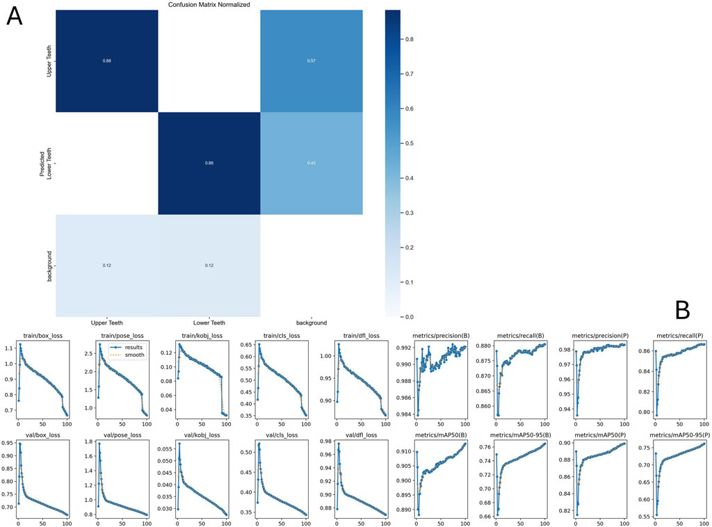
Figure 3. Neural net training results after 100 epoch. (A) Confusion matrix indicating the accuracy of detecting upper vs lower arch. (B) Training metrics. Please refer to text for interpretation of key metric Kobj_loss. Further details are available at https://docs.ultralytics.com/guides/yolo-performance-metrics/#how-can-validation-metrics-from-yolo11-help-improve-model-performance.
Error estimates
Planar accuracy
The planar resolution is calculated from the “camera matrix” camera model. A real-time streaming resolution of 896x504 pixels is used as the input resolution for the Yolo model. A spatial discrimination subtended by 1 pixel is determined by the formula:
Where e is the error subtended by p pixels. f is the focal distance in pixels, D is distance to target.
At 45 cm working distance, the error subtended by 1 pixel is ∼0.61 mm.
Depth accuracy
Depth error of an object of known dimensions estimated by the pixel-wise method can similarly be calculated. The depth error d is inversely proportional to the maximum dimension of the object (in pixels) and increases with the distance.
Using the above error estimate, and an average intercanine distance (w) of 33 mm, the depth error d of a full pixel error is 8.85 mm.
The accuracy of Microsoft’s ToF depth sensor is dependent on the depth measured and is reported as 5 mm at 50 cm in some publications (Mar et al., 2024).
The Depth Accuracy of stereo systems is dependent on the pixel pitch and square of the distance measured.
Where Delta z is the depth error, Delta d is the pixel error, f is the focal distance in mm, and b is the baseline (distance between stereo cameras). Due to sampling multiple “feature” pairs, some authors report the pixel error can be decreased to 0.2 pixels (c.f. NI vision systems). In the HoloLens system, where f is 8 mm, b is 10 cm, the pixel depth error is 4.43 mm at 45 cm.
Detector errors
A yolov8n model was trained as above. The results of training are shown in Figure 3. The reported “pose error” (c.f. Ultralytics) is 0.92 pixels. This corresponds to a planar error of 0.56 mm at a working distance of 45 cm.
Experimental results
An example of the experimental setup and the resulting overlay results are shown in Figure 4.
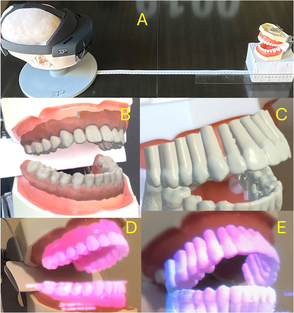
Figure 4. (A) Experimental setup: The headset is placed at a “working distance” from the typodont model. Headset pose data (in “world space”) and “object pose” (in “camera space”) are obtained and used for calculations. (B,C) Synthetic overlay of typodont model and “typodont roots” obtained using in-device “Mixed Reality Capture” functionality. (D,E) Through-the-lens camera capture of the same scenes using a digital camera.
Functionality. D, E: Through-the-lens camera capture of the same scenes using a digital camera. 34 poses were collected, with 4 poses containing only upper arch detection. 34 poses were used for upper arch calculations, while 30 were used for the lower arch. No pose estimates were excluded (i.e., no “outlier” exclusion). The system runs at 30 fps, and performs 7.5-9 pose estimations per second.
Headset pose
The headset was stationary for the duration of testing. The standard deviation of the collected headset poses is shown in Table 1.

Table 1. Precision of normalized results relative to camera (operator) orientation. X, Y, Z indicate linear precision in millimeters, RotX, RotY, and RotZ indicate angular precision in degrees.
Upper arch
Camera space pose estimates for the upper arch are shown in Table 1 and Figure 5.
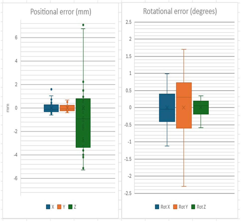
Figure 5. Positional and Rotational precision of Upper Arch detection in “camera space”.
Composite pose (“world space”) estimates are shown in Table 1 and Figure 6.
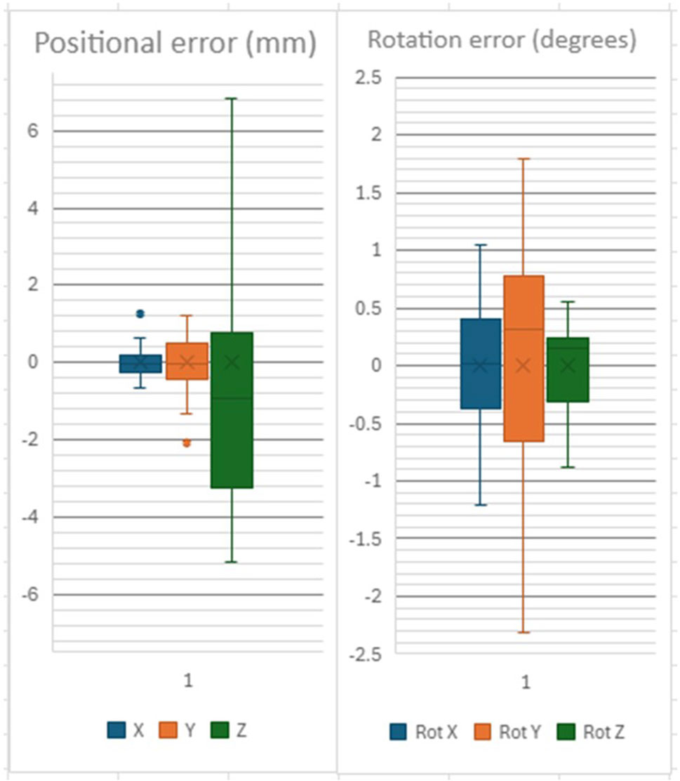
Figure 6. Positional and Rotational precision of Upper Arch detection in “world space”.
Lower arch
Camera Space error estimates are shown in Table 1 and Figure 7.
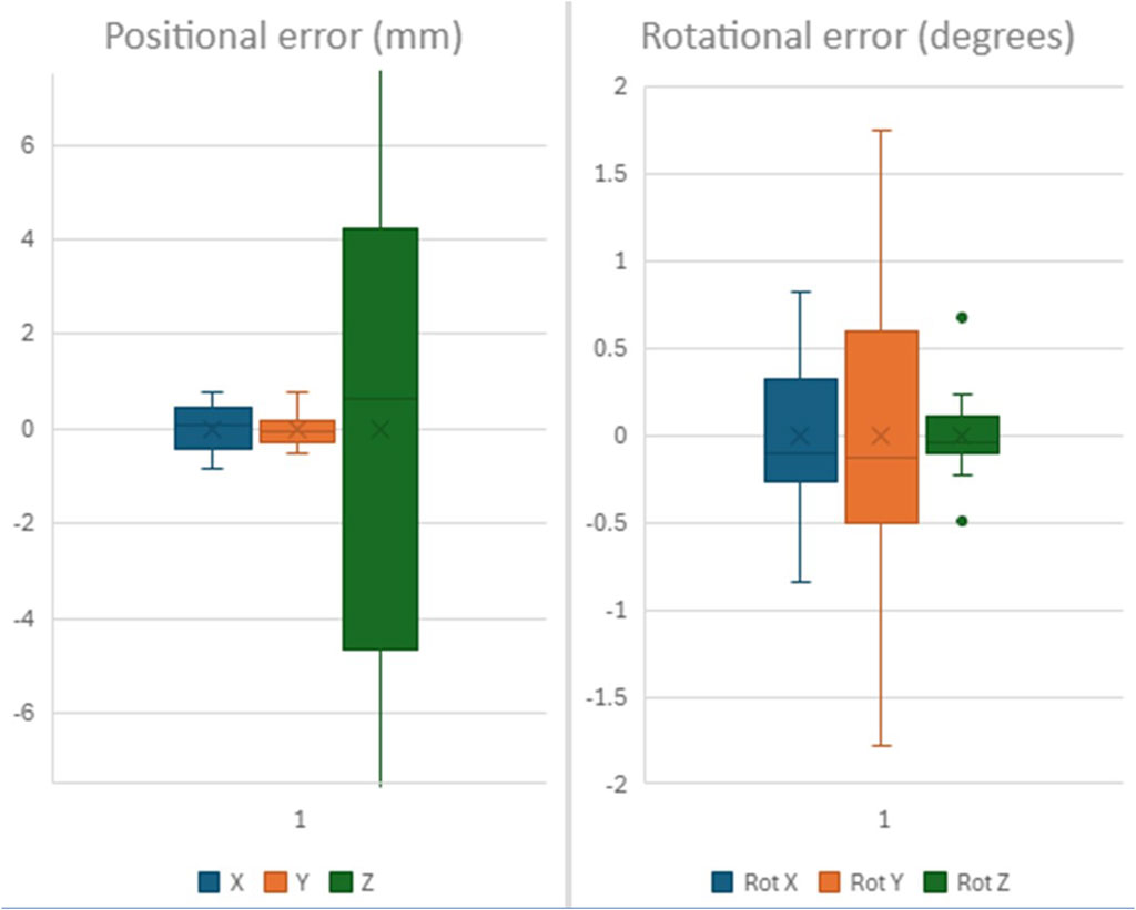
Figure 7. Positional and Rotational precision of Lower Arch detection in “camera space”.
World Space pose estimates for the lower arch are shown in Table 1 and Figure 8.
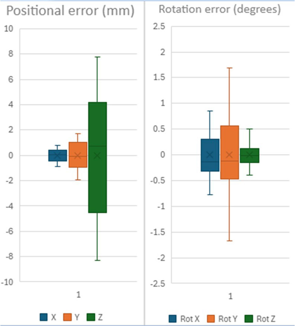
Figure 8. Positional and Rotational precision of Lower Arch detection in “world space”.
Discussion
The focus of this paper is the precision of a vision-based pose estimation system, that is, the consistency or repeatability of the system’s outputs under identical conditions. Precision reflects internal variability and is a critical early step in system validation. In contrast, accuracy refers to how close those outputs are to ground truth or real-world measurements. Our controlled bench-top setup deliberately minimizes user-dependent and environmental variability (e.g., motion, lighting, occlusions), allowing us to isolate and characterize internal system fluctuations. This distinction enables us to establish baseline system performance without conflating it with downstream application noise. Subsequent work will assess accuracy in real-world conditions using ground-truth tools such as optical trackers or robotic arms.
Pose estimation using keypoint detection, as opposed to “Deep Pose Estimation” method which estimates the pose directly from the image, has the advantage of a lighter computing footprint, and is compatible with mobile systems. So-called “state-of-the-art” yolov8 and v11 detectors also offer the flexibility of detecting multiple arches (upper vs. lower), allowing for some anatomical variations in arch form, missing dentition, orthodontic appliances, etc. Conversely, separate calculations are needed to obtain the pose estimations.
This “off-the-shelf” system achieves sub-millimeter planar precision (∼0.56 mm) and angular error below 1°, which aligns closely with clinical tolerances reported for orthodontic bracket placement. Studies have shown that deviations within ±0.5 mm in linear position and ±2° in angulation are generally acceptable and fall within the range of conventional indirect bonding systems or transfer trays (Aboujaoude et al., 2022; Koo et al., 1999). For TAD placement, clinical safety margins are more stringent: horizontal deviations exceeding 1.5–2 mm may risk root contact or affect primary stability, particularly in interradicular sites (Liou et al., 2004; Schnelle et al., 2004). Given our observed depth variability (∼5 mm), the current system is not suitable as a stand-alone guide for depth-critical procedures like unsupervised TAD placement. However, it may support planar guidance by visually projecting root anatomy to assist practitioners in selecting insertion zones between roots. This visual augmentation can enhance operator judgment while allowing traditional mechanical depth control through screw length or physical depth stops. Currently, alternatives for TAD placement include visual estimation of root orientation and 3D printed guides (Bae et al., 2013; Amm et al., 2023). CV-based guidance methods offer significant potential advantages in simplicity and costs for the latter, and accuracy for the former.
Keypoint selection is critical in this task. Occlusal keypoints (cusp tips and incisor contacts) are high-contrast, point-like features that can be reliably identified on digital images, with sharp dental points demonstrating sub-millimeter reproducibility in 3D scans (Park et al., 2019). Gingival margin keypoints, while broader, serve as stable reference markers at the tooth base and have been utilized in digital model analyses of tooth movement (Levrini et al., 2021). Notably, arch expansion studies measure changes at both cusp-tip and cervical/gingival margin points, underscoring the importance of including both types of landmarks when tracking orthodontic movement (Levrini et al., 2021; Houle et al., 2017). By combining occlusal and gingival points, this 30-landmark scheme captures both the tooth crown and base, providing robust anchor points for pose estimation. Such a multi-point configuration is consistent with earlier orthodontic imaging workflows that employed similar dental keypoints for model alignment and tracking (Park et al., 2019; Houle et al., 2017).
Correct Keypoint detection is critical to a correct pose-estimation. Neural Network engineering for keypoint detection is beyond the scope of this article, but several excellent research papers are available (Yang et al., 2023). In short, keypoints are detected based on local or regional image features such as lips, gingiva, etc. depending on the training dataset. We avoided using facial features and minimized inclusion of lips since they are likely to be covered during the intervention. Similarly, a sampling of cheek retractor type and color was included but its use minimized. Conversely, partial “occlusion” and “distractors” was emphasized in the training dataset.
Empirically, common detection errors included incorrect arch detection (i.e., lower arch confused to upper arch and vice-versa), and “frame-shift errors (i.e., premolar confused with canine, due to dental self-similarity) resulting in rotational error of the arch corresponding to skipping one dental crown width. The network design (Ultralytics Yolov8n-pose) is robust to partial occlusion, and provides best-guess estimates of occluded keypoints, including the unseen contralateral dentition. Occluded keypoints have lower precision, but attempts at using only high precision keypoints for pose estimation did not yield higher precision results for the dental arch pose.
Vision-based detection systems have proven highly accurate in detecting planar features, but suffer from imprecision related to depth estimation. Stereovision systems perform better in such use-cases. They rely on “stereo disparity”, by detecting the difference in pixels of similar features between right and left images. Scanning for all possible ranges of pixel disparity requires larger computing power and slows the system down. Therefore, most stereo vision systems are optimized to certain depths. The depth accuracy is inversely proportional to the square of the distance. Similarly, Time-Of-Flight sensors (TOF) emit photons, typically from an InfraRed Laser source, detect their reflection, and estimate the distance traveled by the phase change of the photon wavelengths. Their accuracy is inversely proportional to the linear distance (e.g., 1% of distance between 0 and 2 m reported for the HoloLens 2 (Mar et al., 2024)) but displays a periodic variability within the distance bracket.
Precision of headset pose estimation (Table 1), which constantly estimates the pose of the headset in space, provided by the Augmented Reality platform, is an order of magnitude smaller than the precision of the pose detection system. Nonetheless, the combination of the two poses, to generate the “world space” estimate, resulted in a noticeable increase in pose error of Y estimates (Table 1). The reason why headset pose would affect the Y estimates preferentially is not known. Although the headset was secured to a rigid platform, environmental micro-motions and vibrations were not measured in this experiment. Furthermore, the detected object dimensions in the experimental set-up (see photos) are smaller in the Y-dimension, making them more sensitive to compound error added by the headset’s “spatial tracking” systems.
The precision of the estimates is below 1 mm and 1°, except for depth estimates, which are within 5 mm, as expected from our depth error estimates. The experimental results confirm our theoretical estimates for pipeline accuracy. These results suggest a sub-pixel average error for the keypoint detector, averaging over visible keypoints. Further work is needed to characterize individual keypoint accuracy, and its effect on overall pose estimation.
Depth error remains the major source of imprecision in our results. The experimental “monocular” depth precision reported is within the range of the errors expected from un-optimized stereo-discrepancy systems and the TOF sensor (∼5 mm). Incremental improvements can be expected from optimizations of existing systems, and increasing image resolution, but a quantitative leap could be obtained from a networked “system of sensors”: Since planar estimates are more accurate, depth error can be mitigated by using two perspective views at 90°.
This experimental design does not address errors related to projection of the models back into the user’s eyes. A similar, reverse pipeline exists between the virtual representation of the scene models, “near eye displays” and the operator’s eyes. This will be the focus of a sister paper submitted to this journal.
The precision of this system can be judged to be sufficient for certain orthodontic tasks that require planar accuracy, such as providing visual augmentation of the dental roots during placement of TAD anchors, but not for tasks that depend on accurate depth estimates, such as endodontic work or others. Further pre-clinical and clinical work is needed to assess the applicability of such systems.
The low precision of depth estimates restricts the applications of pure CV-based registration algorithms to tasks that rely on planar accuracy, where depth precision is less important. TAD placement under CV-guidance for example, would overlay the tooth roots thereby allowing the practitioner to choose a placement site in between them. Since the practitioner is wearing the headset, the CV-cameras have the same approximate perspective on the surgical field. The planar overlay is therefore expected to be correct in the operator’s perspective. The depth of insertion of the screw is pre-determined by the length of the TAD chosen, therefore minimizing the impact of depth inaccuracies. It is, however, important to repeat CV-based registration whenever the operator of the subject changes perspective. Overlaying the crowns offers a direct and intuitive way for the operator to detect deviations in registration.
Conversely, tasks such as external approaches to root abscesses require precise depth tracking. In such cases, compensatory methods are needed, such as Multiview registrations or use of physical, typically 3D printed guides as a depth stop. The precision of such mitigatory methods is beyond the scope of this paper. For further discussions on the use of computer vision in dentistry and orthodontics, please see (Ding et al., 2023; Dinesh et al., 2024).
Conclusion
We described a system architecture for a dental pose estimator that can run real-time or near real-time on a mobile system. We describe the training of a custom vision detector for dental keypoints. We provided a theoretical and experimentally derived estimate of the precision of such systems. This off-the-shelf system’s precision suggests potential selected orthodontic applications. Directions for future studies are also shared herein.
Data availability statement
The raw data supporting the conclusions of this article will be made available by the authors, without undue reservation.
Author contributions
EA: Conceptualization, Data curation, Methodology, Supervision, Writing – original draft, Writing – review and editing. MM: Conceptualization, Data curation, Methodology, Visualization, Writing – review and editing. MF: Conceptualization, Data curation, Formal Analysis, Investigation, Methodology, Software, Visualization, Writing – review and editing. VS: Writing – review and editing, Data curation, Methodology, Conceptualization, Formal analysis. ES: Writing – review and editing, Methodology, Supervision, Conceptualization, Validation. JP: Conceptualization, Data curation, Formal Analysis, Methodology, Software, Validation, Writing – review and editing. CE: Conceptualization, Data curation, Formal Analysis, Investigation, Methodology, Project administration, Supervision, Writing – original draft. SM: Conceptualization, Methodology, Project administration, Resources, Supervision, Writing – review and editing.
Funding
The author(s) declare that no financial support was received for the research and/or publication of this article.
Conflict of interest
Author MF, VS, ES, and JP was employed by Xironetic.
The remaining authors declare that the research was conducted in the absence of any commercial or financial relationships that could be construed as a potential conflict of interest.
Generative AI statement
The author(s) declare that Generative AI was used in the creation of this manuscript. ChartGPT was used to shorten an initial draft of the abstract to an accepted size.
Any alternative text (alt text) provided alongside figures in this article has been generated by Frontiers with the support of artificial intelligence and reasonable efforts have been made to ensure accuracy, including review by the authors wherever possible. If you identify any issues, please contact us.
Publisher’s note
All claims expressed in this article are solely those of the authors and do not necessarily represent those of their affiliated organizations, or those of the publisher, the editors and the reviewers. Any product that may be evaluated in this article, or claim that may be made by its manufacturer, is not guaranteed or endorsed by the publisher.
Supplementary material
The Supplementary Material for this article can be found online at: https://www.frontiersin.org/articles/10.3389/frvir.2025.1652074/full#supplementary-material
References
Aboujaoude, R., Kmeid, R., Gebrael, C., and Amm, E. (2022). Comparison of the accuracy of bracket positioning between direct and digital indirect bonding techniques in the maxillary arch: a three-dimensional study. Prog. Orthod. 23 (1), 31. doi:10.1186/s40510-022-00426-3
Amm, E. W., Parsi, G. K., and Motro, M. (2023). In-house temporary skeletal anchorage device guide: free and simple. AJO-DO Clin. Companion 3 (4), 296–305. doi:10.1016/j.xaor.2023.06.004
Bae, M. J., Kim, J. Y., Park, J. T., Cha, J. Y., Kim, H. J., Yu, H. S., et al. (2013). Accuracy of miniscrew surgical guides assessed from cone-beam computed tomography and digital models. Am. J. Orthod. Dentofac. Orthop. 143 (6), 893–901. doi:10.1016/j.ajodo.2013.02.018
Dinesh, R., Ahmad Al, J., Rohan, J., and Viritpon, S. (2024). Artificial intelligence in dentistry and dental biomaterials. Front. Dent. Med. 5, 1525505. doi:10.3389/fdmed.2024.1525505
Ding, H., Wu, J., Zhao, W., Matinlinna, J. P., Burrow, M. F., and Tsoi James, K. H. (2023). Artificial intelligence in dentistry—a review. Front. Dent. Med. 4, 1085251. doi:10.3389/fdmed.2023.1085251
Houle, J. P., Piedade, L., Todescan, R., and Pinheiro, F. H. (2017). The predictability of transverse changes with Invisalign. Angle Orthod. 87 (1), 19–24. doi:10.2319/122115-875.1
Koo, B. C., Chung, C. H., and Vanarsdall, R. L. (1999). Comparison of the accuracy of bracket placement between direct and indirect bonding techniques. Am. J. Orthod. Dentofac. Orthop. 116 (3), 346–351. doi:10.1016/s0889-5406(99)70248-9
Levrini, L., Carganico, A., and Abbate, L. (2021). Maxillary expansion with clear aligners in the mixed dentition: a preliminary study with Invisalign® First system. Eur. J. Paediatr. Dent. 22 (2), 125–128. doi:10.23804/ejpd.2021.22.02.7
Liou, E. J., Pai, B. C., and Lin, J. C. (2004). Do miniscrews remain stationary under orthodontic forces? Am. J. Orthod. Dentofac. Orthop. 126 (1), 42–47. doi:10.1016/j.ajodo.2003.06.018
Lo, Y.-C., Chen, G.-A., Liu, Y.-C., Chen, Y.-H., Hsu, J.-T., and Yu, J.-H. (2021). Prototype of augmented reality technology for orthodontic bracket positioning: an in vivo study. Appl. Sci. 11 (5), 2315. doi:10.3390/app11052315
Martin-Gomez, A., Li, H., Song, T., Yang, S., Wang, G., Ding, H., et al. (2024). STTAR: surgical tool tracking using off-the-shelf augmented reality head-mounted displays. IEEE Trans. Vis. Comput. Graph. 30 (7), 3578–3593. doi:10.1109/TVCG.2023.3238309
Olawade, D. B., Leena, N., Egbon, E., Rai, J., Mohammed, APEK, Oladapo, B. I., et al. (2025). AI-driven advancements in orthodontics for precision and patient outcomes. Dent. J. 13 (5), 198. doi:10.3390/dj13050198
Park, J., Baumrind, S., Curry, S., Carlson, S. K., Boyd, R. L., and Oh, H. (2019). Reliability of 3D dental and skeletal landmarks on CBCT images. Angle Orthod. 89 (5), 758–767. doi:10.2319/082018-612.1
Riad Deglow, E., Zubizarreta-Macho, Á., González Menéndez, H., Lorrio Castro, J., Galparsoro Catalán, A., Tzironi, G., et al. (2023). Comparative analysis of two navigation techniques based on augmented reality technology for the orthodontic mini-implants placement. BMC Oral Health 23, 542. doi:10.1186/s12903-023-03261-y
Rodríguez-Ortega, J., Pérez-Hernández, F., and Tabik, S. (2025). CHaRNet: conditioned heatmap regression for robust dental landmark localization. arXiv Prepr. doi:10.48550/arXiv.2501.13073
Schnelle, M. A., Beck, F. M., Jaynes, R. M., and Huja, S. S. (2004). A radiographic evaluation of the availability of bone for placement of miniscrews. Angle Orthod. 74 (6), 832–837. doi:10.1043/0003-3219(2004)074<0832:AREOTA>2.0.CO;2
Tremblay, J., To, T., and Birchfield, S. (2018). “Falling things: a synthetic dataset for 3D object detection and pose estimation,” in CVPR workshop on real world challenges and new benchmarks for deep learning in robotic vision.
Keywords: augmented reality, extended reality (VR/AR/MR), computer vision, orthodontics, temporary anchorage device (TAD), pose estimation
Citation: Amm E, Motro M, Fisher M, Surdu V, Strong EB, Potts J, El Amm C and Maqusi S (2025) A critical appraisal of computer vision in orthodontics. Front. Virtual Real. 6:1652074. doi: 10.3389/frvir.2025.1652074
Received: 23 June 2025; Accepted: 29 August 2025;
Published: 20 October 2025.
Edited by:
Heather Benz, Johnson & Johnson Medtech (US), United StatesReviewed by:
Jishnu S., Malabar Dental College, IndiaDianhao Wu, University of Science and Technology Liaoning, China
Copyright © 2025 Amm, Motro, Fisher, Surdu, Strong, Potts, El Amm and Maqusi. This is an open-access article distributed under the terms of the Creative Commons Attribution License (CC BY). The use, distribution or reproduction in other forums is permitted, provided the original author(s) and the copyright owner(s) are credited and that the original publication in this journal is cited, in accordance with accepted academic practice. No use, distribution or reproduction is permitted which does not comply with these terms.
*Correspondence: Suhair Maqusi, c3VoYWlyLW1hcXVzaUBvdWhzYy5lZHU=