 T. Lee
 G. Lin
- Department of Mechanical Engineering, McGill University, Montreal, QC, Canada
The ground effect-induced large lift increase and lift-induced drag reduction have long been recognized and utilized in the design and construction of wing-in-ground effect (WIG) craft. Various wing planforms have been employed in WIG craft. In this study, the experimental investigations of rectangular wings and delta wings of reverse and regular configurations at low Reynolds numbers are reviewed. For rectangular wings, both chord-dominated and span-dominated ground effects on the aerodynamics, tip vortex, and lift-induced drag are reviewed. For reverse delta wings, in addition to the experimental measurements of the aerodynamics and tip vortex flow at different ground distances, passive flow control utilizing Gurney flap, cropping, and anhedral are reviewed. The impact of ground effect on delta wings is also discussed. Suggestions for future investigations applicable to each wing planform in-ground effect are provided.
1 Introduction
The large lift augmentation and lift-induced drag reduction have long been recognized when an airplane is flying close to the ground, especially during landing and takeoff. The ground proximity also causes an unwanted extra lift or the so-called “floating” experienced by the pilots. The ground effect-induced aerodynamic benefits have also been exploited by large birds, such as albatross, in long-distance flight to conserve energy. The Wright brothers’ maiden flight was in fact completely in ground effect. The ground effect-induced large lift increase and lift-induced drag decrease have also been utilized extensively in winged ground-effect vehicles (GEVs) or wing-in-ground effect (WIG) craft. The WIG craft flying just meters above the water surface with various wing planforms and configurations have been designed and constructed since the 1960s. Among them, the Russian Ekranoplans (started with the Caspian Sea Monster, followed by A-90 Orlyonok and, most recently, Chaika A-059) employing a pair of giant rectangular wings of a small aspect ratio have been constructed since the 1960s. Eight power augmented ram (PAR) turbojet engines together with large trailing-edge flaps are necessitated to overcome the huge ‘‘hump drag’’ during takeoff, which inevitably increase the weight and complexity of the Ekranoplan WIG system. Moreover, a large horizontal stabilizer or tail is also required to mitigate the ground proximity-produced longitudinal instability. Extensive reviews on the Ekranoplan-type WIG craft were given by Halloran and Sean O’Meara (1999), Rozhdestvensky (2006), and Yun et al. (2010). To overcome the inherent longitudinal instability of the small aspect-ratio rectangular wing-in-ground effect and to eliminate the necessity of the PAR wing, Lippich-type WIG craft (started with X-112, followed by RFB X-114 and, most recently, AirFish-8) employing a reverse delta wing planform with built-in anhedral was pioneered by Dr. Alexander Lippish in the 1970s. The addition of the anhedral to the reverse delta wing not only creates a high-pressure ‘‘air tunnel’’ (as described by Kocivar (1977)) increasing the ram pressure acting on the wing’s lower surface but also considerably reduces the hydrodynamic drag during takeoff by submerging only the tips or sponsons of the anhedral wing into the water. The high lift-to-drag ratio of the reverse delta wing in conjunction with a small T-tail makes the Lippisch-type WIG craft operational and popular.
Extensive theoretical, numerical, and experimental investigations of the ground effect on the aerodynamic performance, including the lift-induced drag, and flow field of wings of different planforms have been conducted by researchers elsewhere. Theoretical ground-effect studies of conventional wings using the discrete vortex method can be found in the work of, for example, Plotkin and Kennel (1981), Han and Choi (2005), Gross and Traub (2012), Han and Kinnas (2013), Mondal and Balakrishnan (2014), and Mondal (2015). In comparison to reverse delta wings, the impact of ground effect on rectangular wings has been studied extensively. To limit the scope of this review, this study was concentrated on experimental investigations of the ground effect on the aerodynamics and tip vortex flow including the lift-induced drag of rectangular and delta wing, of both reverse and regular configurations, at low Reynolds numbers. Section 2 focuses on the chord-dominated and span-dominated ground effects on rectangular semi-wings. Both static and unsteady airfoils over flat and wavy grounds were reviewed. The discrepancy arose from stationary and moving ground conditions was also summarized. Section 3 focuses on the experimental investigations of the behavior of the aerodynamics and tip vortex flow of reverse delta wing in ground effect. Passive control schemes involving Gurney flap, cropping, and anhedral were also reviewed. In Section 4, the aerodynamics and the behavior of leading-edge vortices developed over a regular delta wing under the influence of ground proximity were also discussed. The aerodynamics and flow field characteristics of each wing planform outside the ground effect were also reviewed to serve as a comparison. Finally, suggestions applicable to each wing planform were provided in Section 5 for future experimental investigation.
2 Rectangular wing planform in ground effect
The ground effect on rectangular wings and airfoils is of both fundamental and practical importance. For a rectangular wing planform with isolated end effects, the ground effect-produced lift increases, resulting from the ram pressure or the dynamic air cushion developed in the narrowed flow passage between the airfoil’s lower surface and the ground surface, can be attributed to the so-called chord-dominated ground effect (CDGE). For finite wings, the lift-induced drag reduction and the outboard movement of the wingtip vortices as the ground is approached are mainly referred to as the span-dominated ground effect (SDGE). The combined chord-dominated and span-dominated ground effects give rise to an increased lift-to-drag ratio of the winged GEV as compared to its outside ground effect counterpart. The CDGE on the aerodynamics and flow structure of the airfoils have been investigated extensively. However, due to the different ground boundary conditions, Reynolds numbers, airfoil profiles, flow facilities, and analysis methods employed, there exists a large scatter in the published CDGE-induced sectional lift Cl and drag Cd coefficients and the flow field characteristics of the airfoil. By contrast, investigations on the impact of span-dominated ground effect on the tip vortices, especially the lift-induced drag, are limited. A large discrepancy also exists in the archived vortex flow and lift-induced drag in ground proximity. In this section, typical experimental CDGE investigations were reviewed first, followed by the impact of SDGE on the tip vortices and the associated lift-induced drag. The CDGE investigation started with flat surface, both stationary and moving, followed by wavy ground or wall. Both static and unsteady airfoils in ground effect were considered. The SDGE investigation was focused on the aerodynamic and tip vortex characteristics, especially the calculation of lift-induced drag, in ground effect. To facilitate the review of ground effect on rectangular wings and airfoils, the outside-ground effect was summarized first and serves as a comparison.
2.1 CDGE
2.1.1 Flat ground
The aerodynamics and flow structure of airfoils of various profiles subjected to both stationary and moving flat ground surfaces at different low Reynolds numbers were investigated extensively by Carter (1961), Turner (1966), Hayashi and Endo (1978), Suh and Ostowari (1988), Tomaru and Kohama (1990), Hsiun and Chen (1996), Steinbach (1997), Moore et al. (2002), Barber et al. (2002), Ahmed and Sharma, (2005), Ahmed et al. (2007), Ghadimi et al. (2012), Luo and Chen (2012), Qu et al. (2014), Qu et al. (2015a), He et al. (2018), Lee et al. (2018), and Tremblay-Dionne and Lee (2021).
Carter’s (1961) towing tank study showed that the ground proximity caused an increased lift-curve slope while the profile drag remained virtually unaffected. α is the angle of attack. Turner (1966) reported that the stationary ground proximity produced a drastic increase in Cl of the airfoil. A 33% Cl increment was obtained at h/b = 33% (where h is the distance between the airfoil’s trailing edge and the ground, and b is the wingspan) as compared to its outside ground effect counterpart. Hayashi and Endo (1978) found both numerically and experimentally that in stationary ground effect the flow separation occurred earlier, resulting in a larger wake behind a NACA 4412 airfoil at α = 15° and a chord Reynolds number Re = 3.2 × 10⁵. Suh and Ostowari (1988), however, indicated that the stationary ground effect produced a reduced Cd accompanied by increased flow separation, leading to an increased Cl/Cd. Steinbach (1997) also observed that the flow separation was enlarged and the drag was reduced as the moving ground was approached. The moving ground was achieved via boundary-layer suction. Hsiun and Chen (1996) simulated numerically the flow separation over a NACA 4412 airfoil at α ≤ 10° for Re = 3.2 × 10⁵ and concluded that both Cl and Cd were a strong function of the stationary ground clearance. Steinbach (1997) pointed out that Cl was affected by the boundary layer developed on the stationary ground surface for h ≤ 5% airfoil chord c, and that the slip boundary condition should be considered.
Moore et al. (2002) further reported that both Cl and Cd of a NACA 0012 airfoil at Re ≤ 8 × 10⁵ were increased with decreasing ground distance in a rolling road wind tunnel. For α ≤ 3°, the Cl reduction was attributed to the abnormal suction effect developed on the airfoil’s lower surface due to the convergent-divergent passage developed between the airfoil and the ground surface. They divided the ground effect into two distinct regimes: ram effect for h/c ≤ 10% and normal ground effect for h/c > 10%. In the ram effect, an almost sealed envelope is created between the wing’s trailing edge and the ground surface. As h/c increases above 10%, the wing enters what is normally considered to be the normal ground effect. Barber et al. (2002) indicated numerically that there was a large Cl discrepancy between moving and stationary ground effect in close ground proximity at Re = 8.2 × 10⁶ and α = 2.9°, and that only a small Cl difference existed for h/c > 10%. A recirculation region was visible beneath the airfoil’s leading edge at h/c = 2.5% over the stationary ground. The numerical results were also supplemented by limited particle image velocimetry (PIV), flow field measurements at Re = 6.1 × 10⁴. They concluded that viscous effects are significant for the ground-effect flight and it is unlikely that inviscid solutions will give an accurate representation of the ground-effect aerodynamics.
Ahmed and Sharma (2005) reported experimentally that the surface pressure coefficient Cp increased on the airfoil’s lower surface as the stationary ground was approached, leading to an increased Cl. Also, the flow accelerated over the airfoil due to flow diversion from the lower surface especially for higher α, resulting in a thicker wake and hence higher drag. Ahmed et al. (2007) further showed that in moving ground effect the Cl of a NACA 4412 airfoil at Re = 3 × 10⁵ increased with decreasing h/c for high α while decreased with reducing h/c for small α. Only a minor loss of upper surface suction exhibited as the airfoil approached the ground for all α. The high-pressure drag originated from the airfoil’s lower surface which led to increased pressure drag at small h/c for all α tested. They also claimed that as the flow moved toward the trailing edge, the velocity close to the surface reduced to overcome the adverse pressure gradient. Luo and Chen (2012) investigated the stationary ground effect on a NACA 0015 airfoil through load cells and Cp measurements at Re = 1.87 × 10⁵. They found that the Cl decreased with h/c reducing from 30% to 15% for α ≤ 6° due to the convergent–divergent channel effect, and that the Cl generally lay within the magnitude estimated from the thin airfoil theory.
To resolve and quantify the discrepancy arose from the ground boundary conditions, Re, airfoil profiles, flow facilities, and test methods, the aerodynamic and flow field characteristics of a NACA 0012 airfoil subjected to both stationary ground and moving ground effects were investigated in the same wind tunnel flow facility at an identical Reynolds number via PIV and Cp measurements by Tremblay-Dionne and Lee (2021). The moving ground was set up via a moving belt with a surface speed equal to that of the freestream velocity. The laminar boundary layer developed over the stationary ground (simulated by an elevated thin metal plate) had a normalized thickness of δ/c = 1.6%, corresponding to h/c = 1.6%. The ground distance h was the distance between the airfoil’s trailing edge and ground surface (Figure 1A). Tremblay-Dionne and Lee (2021) concluded that for the stationary ground effect, the existence of the longitudinal boundary layer developed on its surface narrowed the flow passage underneath the airfoil, decelerating the flow, and producing a higher Cl than the moving ground (Figure 2A). The change in the sectional pitch-moment coefficient Cm with h/c was depicted in Figure 2C. In ground effect, a nose-up (or nose-down) Cm in the small (or large)-α also exhibited. They also concluded that in close stationary ground proximity the formation of a ground vortex or circulation region beneath the airfoil’s leading-edge region (Figure 2G) speeded up the flow, leading to a lower Cl than the moving ground. For h/c ≥ 20%, no ground vortex was observed (Figure 2H).
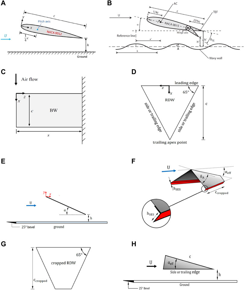
FIGURE 1. Schematics of airfoil and wing models and definition of ground distance h. (A) NACA 0012 airfoil, (B) wavy wall, (C) baseline rectangular semi-wing (BW), (D) reverse delta wing (RDW), (E) RDW and h, (F) RDW with joint cropping, anhedral, and Gurney flap, (G) cropped RDW, and (H) anhedral RDW, and (H) λ = wavelength. A = 2a = wave amplitude. δTE = flap deflection angle.
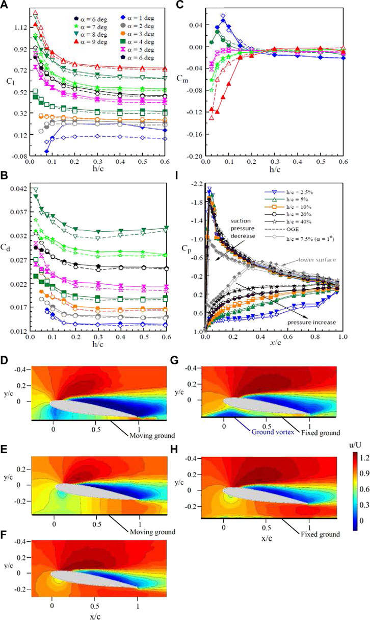
FIGURE 2. Impact of ground boundary conditions on (A–C) Cl, Cd, and Cm; (D–H) iso-ζc/U contours; and (i) Cp distribution at α = 6°and 1°. Open and solid symbols denote the moving and stationary ground, respectively. (D,G): h/c = 5%; (E,H): h/c = 20%; and (F) OGE (Tremblay-Dionne and Lee 2021).
For moving ground, the ground vortex was always absent (Figures 2D,E). The absence of the ground vortex enabled an increase in velocity as the flow speeded up to meet the velocity at the ground surface, causing the flow to remain uniform beneath the airfoil as it approached the moving ground surface. The moving ground effect, however, generated a larger near wake and Cd (Figure 2B) than the stationary ground effect, suggesting an earlier flow separation. The change in Cl can also be reflected in the Cp distribution on the airfoil surface at different h/c at α = 6° (Figure 2I). The moving ground effect generated a larger Cp exerting on the airfoil’s lower surface, leading to a higher Cl and Cd than the stationary ground effect. Only a minor change in Cp developed on the airfoil’s upper surface was noticed regardless of h/c, α, and ground boundary conditions. Figure 2I also confirms at α = 1°, there was a negative Cp which appeared on the airfoil’s lower surface originated from the convergent–divergent flow passage developed underneath the airfoil in close ground proximity. Additional experiments investigating the impact of different moving ground surface speeds on airfoils of different profiles are desired.
In addition to a statice airfoil operating close to a flat ground surface, Lee et al. (2018) also investigated the aerodynamic property of a NACA 0012 airfoil oscillated sinusoidally with α(t) = 11o + 6osinωt motion at a reduced frequency κ (= ωc/2U = πfc/U, where f is the oscillation frequency and U is the freestream velocity) = 0.05 in stationary ground effect via the integration of Cp at Re = 9.81 × 10⁴. A substantial change in the dynamic-Cl loops, especially during the downstroke, occurred for h/c ≤ 30%, leading to a significantly reduced Cl-hysteresis as compared to the OGE case (Figure 3A). The dynamic-stall vortex was found to be weakened and broke down earlier with reducing h/c, rendering an enlarged separated flow than their OGE counterpart. The degree of nose-down pitching moment also increased with reducing ground distance (Figure 3B). Additional experiments covering attached-flow, light- and deep-stall oscillations at different κ are needed. Individual and combined heave and pitch motions in ground effect also demand consideration. It is noteworthy that the impact of joint heave and pitch motion on the aerodynamic property of the airfoil outside the ground effect was investigated by Lee and Su (2015). For the WIG craft, the wavelength, amplitude, and the wave travelling speed of the ocean waves serve as experimental guidelines.
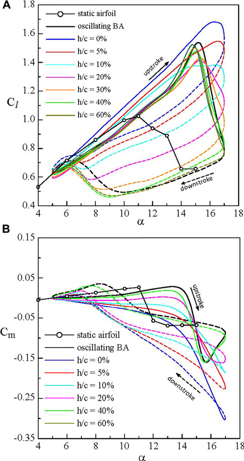
FIGURE 3. Ground effect on the NACA 0012 airfoil oscillated with α(t) = 11° + 6°sinωt motion at κ = 0.05 and Re = 9.81 × 10⁵. (A) dynamic-Cl loop and (B) dynamic-Cm loop obtained via Cp measurement. Solid and dashed lines denote upstroke and downstroke, respectively. BA denotes baseline airfoil (Lee et al., 2018).
2.1.2 Non-uniform ground
Since the WIG craft frequently fly over non-uniform ground, for example, a bump, a wavy terrain, and rough ocean waves, it causes unsteady and non-uniform flow beneath the wing which affects the stability and predictability of its flight dynamics, especially in the vertical plane. Only a limited number of publications are available for the WIG craft flying over non-flat grounds. Most of the non-uniform ground effect were studied by using the simplified sinusoidal wavy ground of various wavelengths and amplitudes. Representative theoretical and numerically work have been conducted by, for example, Ando et al. (1992), Morishita and Ashihara (1995), Im and Chang (2000), Rozhdestvensky (2006), Matveev (2015), and He et al. (2019). The experimental investigation of wavy ground effect was conducted by Tremblay-Dionne and Lee (2019a and 2019b).
Im and Chang (2000) studied numerically the aerodynamic loads of an oscillating NACA 0012 airfoil over a moving sinusoidal wall of an amplitude a = 2.5%c and 10%c and a wavelength λ = 1.5−5c at Re = 3.2 × 10⁵. The normal force coefficient Cn increased as the airfoil was moving toward the crest of the wavy ground and decreased as it moved away from the crest. The Cm was all negative. No Cd was reported in their inviscid-flow calculation. Matveev (2015) modelled the complex flight dynamics due to the wavy ground effect on the vehicle aerodynamics by using potential flow theory. The influence of heave-pitch motion on Cl, Cm, and Cn was studied for flights over wavy surfaces over a range of a and λ. For “extreme” ground effect flow, the dominant lift component was found to be generated on the lower side of the wing, and the flow under the wing became nearly two-dimensional. The influence of the flow in the wake and above the wing on the upper-wing flow were ignored.
Lee and Tremblay-Dionne (2018) measured the aerodynamic and flow properties of a static NACA 0015 airfoil over a wavy ground with λ/c = 1 and 2a = 0.1c at Re = 2.45 × 10⁵ through Cp and PIV measurements in a subsonic wind tunnel. The schematic of the wavy ground and the definition of wavelength λ, peak-to-peak amplitude A = 2a, ground distance h, and measuring position x′ are given in Figure 1B. They observed that there exhibited a cyclic variation in Cl and Cm over an entire wavelength (Figures 4A,B). For λ/c = 1, x′6 is located at the wave valley while x′0 and x′11 are located at the wave peak. The Cm value had an opposite trend to the variation in Cl as well as an almost all-negative value. The maximum Cl occurred at the wave peak (produced by the wavy ground-induced ram pressure) and the minimum Cl occurred at the wave valley (resulting from the unusual suction pressure developed on the airfoil’s lower surface due to the converging–diverging flow passage developed underneath it) reduced with increasing ground distance. The wavy ground effect-produced gain in the mean Cl was, however, at the expense of longitudinal stability. Figure 4C demonstrates the great change in Cp on the airfoil’s lower surface over one wavelength.
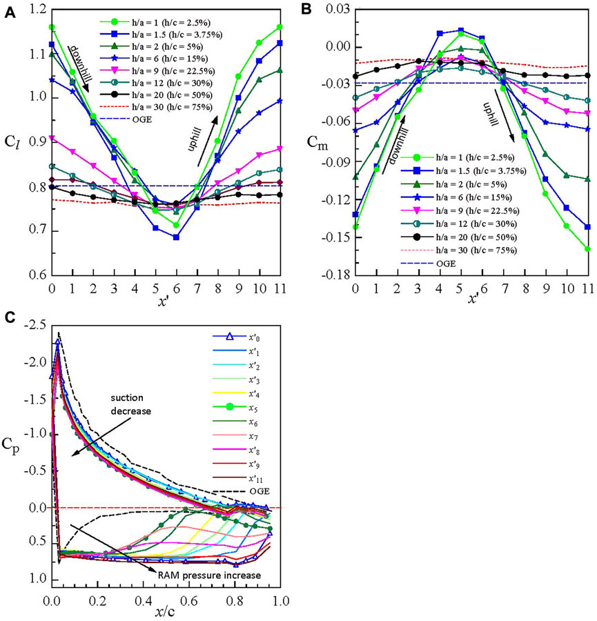
FIGURE 4. Impact of wavelength and amplitude of wavy ground on (A) Cl, (B) Cm, and (C) Cp distribution of the NACA 0015 airfoil over one wavelength for λ/c = 1.2a = 5%λ = 5%c. x′ denotes measuring location. x′6 is located at the wave valley while x′0 and x′11 are located at the wave peak (Lee and Tremblay-Dionne (2018)).
2.2 SDGE
2.2.1 OGE
In this section, the span-dominated ground effect on the wingtip vortices and the lift-induced drag generated by a rectangular semi-wing was reviewed. It is known that outside the ground effect or in a free stream the growth and development of the tip vortices and their impact on the aerodynamics and flight hazards are of both fundamental and practical importance and have been investigated extensively by researchers elsewhere (see, Devenport et al. (1996), Chow et al. (1997), and Ramaprian and Zheng (1997)). An excellent review on airplane trailing vortices outside the ground effect was given by Spalart (1998). Various control techniques, such as winglets, spoilers, stub/subwing, porous tips and leading edges, static and rapidly actuated segmented Gurney flaps, plasma actuators, and zero mass-flux fluidic perturbations, have also been attempted to modify the strength, structure, and trajectory of the wingtip vortices (see, Duraisamy and Baeder (2003), Matalanis and Eaton (2007), Breitsamter and Allen (2009), Hasebe et al. (2011), Greenblatt et al. (2009), Greenblatt (2012), and Lee and Su (2012)). More recently, an alternative wingtip vortex control was proposed by Lee and Choi (2015) by using a tip-mounted small-chord half-delta wings (HDW) of different slenderness Λ, root chords cr, and deflections.
Lee and Choi (2015) reported that, regardless of Λ and cr, the addition of a small HDW to the tip of a rectangular semi-wing at Re = 2.45 × 10⁵ triggered the breakdown of the tip vortex, producing a greatly diffused and circulation flow-like tip vortex (Figure 5B) as compared to its baseline-wing counterpart (Figure 5A). The streamwise vorticity ζ = ∂w/∂y − ∂v/∂z was calculated from the vw-crossflow measurements by using a central differencing scheme to evaluate the derivatives. For the HDW wing, there was the presence of a double vortex system, consisting of a tip vortex and a HDW vortex. Figure 5A is of particular importance in the illustration of the initiation and development of the tip vortex both along the tip and in the near field of a rectangular wing. As can be seen, the baseline-wing tip vortex became nearly developed for x/c ≥ 2. The origin of the coordinates is shown in Figure 1C. For x/c < 1, the interaction and merge of the shear-layer vortices and main vortex leading to the tip vortex (for x/c > 1) can be clearly seen.
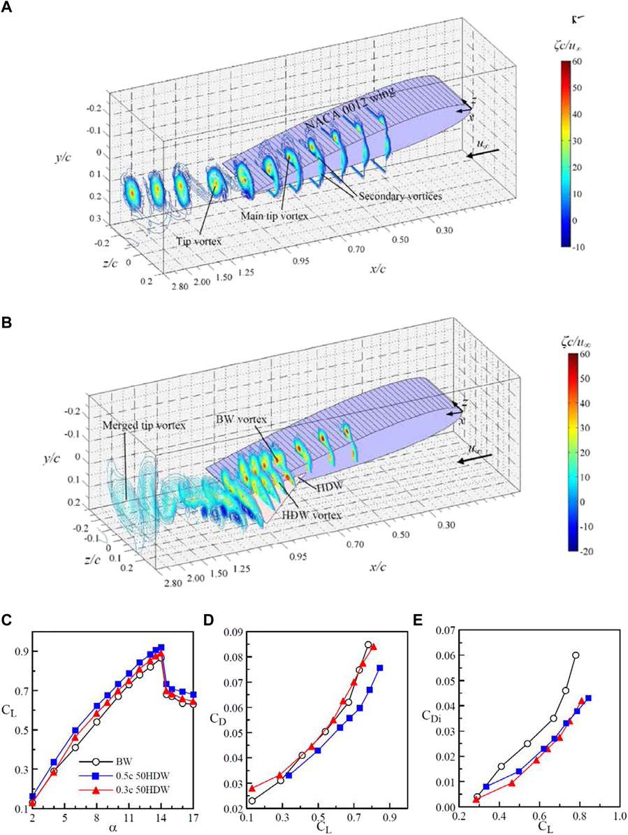
FIGURE 5. (A,B) Schematics and spatial progression of iso-ζc/u∞ contours of baseline wing (BW) and tip-mounted half-delta wing (HDW) for 0 < x/c < 3 at α = 10° and Re = 2.45 × 10⁵. (C–E) CL, CD, and CDi. 0.3c 50HDW denotes half-delta wing with a root chord cr = 0.3c and Λ = 50° (Lee and Su 2012; Lee and Choi 2015).
Lee and Choi further found that the interaction and merging of the double vortex was further expedited by upward HDW deflection. The addition of the small-chord tip-mounted HDW also led to an increased CL and a decreased CD (Figures 5C,D), leading to an improved CL/CD. The CL increase can be attributed to the mitigation of the free end effects provided by the tip mounted HDW. The CD reduction was due to the tip-mounted HDW-caused decrease in the lift-induced drag coefficient CDi [= Di/½ρU2S, where Di is the lift-induced drag and S is the wing area; see Figure 5E). A 10% (or 34%) increase (or decrease) in CL (or CDi) at α = 10o was produced by the 0.3c 50 HDW as compared to the baseline wing. The lift-induced drag Di was computed via the Maskell integral model (Maskell, 1973; Brune, 1994; Kusunose, 1998).
where ψ(y,z) and ϕ(y,z) are stream function and velocity potential, and σ = ∂v/∂y + ∂w/∂z. The details of the lift-induced drag computation were provided in the work of Gerontakos and Lee (2007).
For 2 < x/c < 4.5, the core flow of the tip vortex also became axisymmetric (manifested by the tangential velocity vθ distribution across the vortex center with vθ,max ≈ |vθ,min|), which suggests the near completion of the roll-up of the tip vortex in the near field. Additionally, a core circulation Γc to total circulation Γo ratio of about 74% of the tip vortex in comparison with 71% of Lam’s solution (1941) was also attained. The circulation was computed via Stokes theorem by summing the vorticity multiplied by the incremental area of the measuring grid. The tip vortex measurement also allows the prediction of CL,prediction = 2(Γo/cU) (b′/b) = 0.542 which is 83% CL,FB = 0.651 (measured with a force balance) at α = 10o. b′ is the distance between the center of the tip vortices and b is the wing span. The vortex center was identified by the location of peak vorticity ζpeak.
The CL was also determined based on the integration of the spanwise circulation Γ(z), inferred from the vw-crossflow measurement, and distribution from the whole wake scan (Figure 6A; Lin and Lee, 20221). The lift force L at each α was determined via
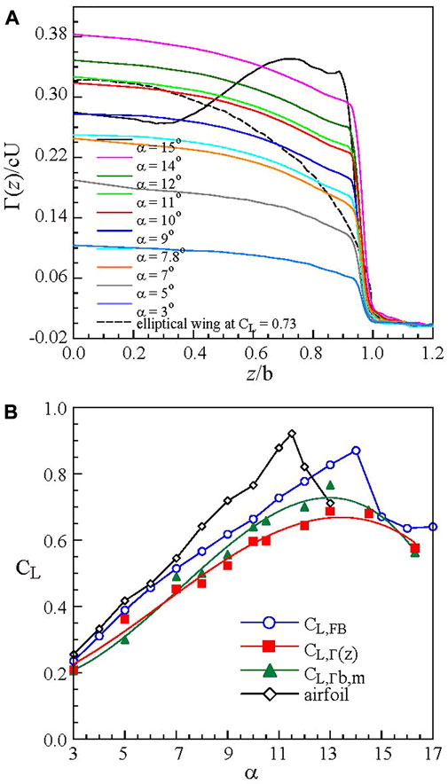
FIGURE 6. (A) Normalized spanwise circulation Γ(z) distribution and (B) CL at different α of a rectangular semi-wing with AR = 1.818 at Re = 2.48 × 10⁵ outside the ground effect (Lin and Lee, 20221).
In Figure 6A, the dip in the Γ(z) distribution near the tip manifests the existence of a tip vortex with a stronger circulation. Special attention should be given to the large increase in Γ(z) at the tip and the great drop in the root bound circulation Γb,m identified at z = 0 for α = 16.3o (< αss = 14o), attributing to the root stall of the rectangular semi-wing. αss is the static-stall angle. For a root-stall wing, most of the inboard of the wing suffers from massive flow separation while the outboard wing region, especially the tip region, remains unaffected. The value of CL,Γ(z) (= L/½ρU2S), obtained through the integration of Γ(z) distribution, was found to be in good agreement with the CL,FB measured directly with a force balance (Figure 6B), suggesting that the circulation distributions were consistent with the measured lift data according to the Kutta–Joukowsky theorem. The prediction of CL,Γ(z) only applied to pre-stall α regime, that is., α ≤ αss. Also, shown in Figure 6B is the prediction of CL,Γb,m = 2Γb,m/cU based on classical Prandtl’s lifting-line theory. The estimated CL,Γb,m appeared to be closer to that of CL,FB and is larger than CL,Γ(z). At α = 10o, CL,Γ(z) = 0.596 and CL,Γb,m = 0.64 in comparison with CL,FB = 0.661 were obtained. Also, presented in Figure 6A is the Γ(z) distribution of an elliptical wing for a direct comparison. Extension of the CL determination based on the vw-crossflow measurements to in-ground effect is highly desired.
2.2.2 IGE
In this section, the effect of ground effect, both stationary and moving, on the tip vortex flow was reviewed. Lu et al. (2019) found that in close stationary ground proximity, there existed a unique multiple vortex system, consisting of a tip vortex (TV), a co-rotating ground vortex (GV), and a counter-rotating secondary vortex (SV), downstream of the rectangular wing (see Figure 7A). The ground vortex adds vorticity to the tip vortex while the secondary vortex negates its vorticity. The ground vortex formed beneath the airfoil’s leading-edge region was caused by the ground effect-produced ram pressure which pushes the streamwise boundary-layer flow backwards and toward its leading edge and rolling up into the observed recirculation region (as discussed earlier in Figure 2G). The secondary vortex was first observed experimentally by Harvey and Perry (1971) and was numerically simulated later by Corjon and Poinsot (1997), Puel and Victor (2000), and Holzapfel and Steen (2007). Harvey and Perry found that as a vortex descended close to the ground during landing and takeoff, the crossflow of the tip vortex gave rise to a spanwise boundary layer which rolled up into a counter-rotating secondary vortex relative to the descending tip vortex. In addition to the appearance of the multiple vortex system in close ground proximity, a large scatter in vortex flow characteristics and Di also exists due to different ground boundary conditions, Re, flow facilities, wing planforms, and airfoil profiles employed (see, Chun et al. (1996), Joh and Kim (2004), Han and Choi (2005), Lee et al. (2010), Lu et al. (2019), and Lu and Lee (2021)).
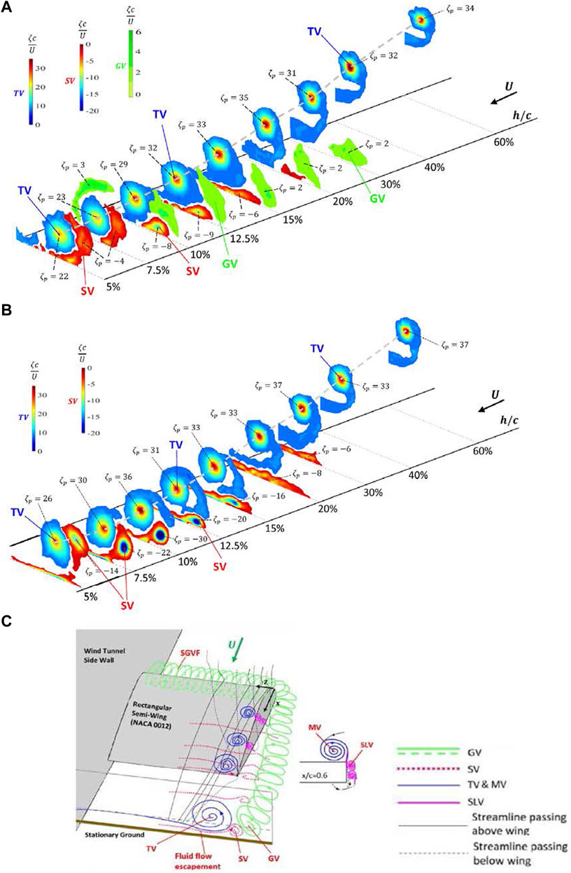
FIGURE 7. Effect of ground boundary conditions on iso-ζc/U contour at different h/c for α = 10°. (A) Stationary ground and (B) moving ground. ζp (= ζpeakc/U) denotes normalized peak vorticity of the vortex. Gray dashed line denotes vortex center location. GV, MV, SLV, SV, and TV denote ground vortex, main vortex, shear-layer vortex, secondary vortex, and tip vortex, respectively. (C) Conceptual sketch of the existence of the spanwise ground vortex filament (SGVF) and its downstream development into the ground vortex, the formation of SV, and the evolution of MV, SLV, and TV. The evolution and streamlines is adapted from Chow et al. (1997) (Lu and Lee 2021).
Chun et al. (1996) reported that the stationary ground effect resulted in an insufficient space for the tip vortices to grow, causing a reduced lift-induced drag. Tuck and Standingford (1996) showed that the lift-induced drag increased with decreasing ground distance. The ground proximity-produced lift increase and the lift-induced drag decrease were also observed by Joh and Kim (2004). Han and Choi (2005) demonstrated theoretically that there was a lateral vortex displacement and reduction in the vortex strength in ground effect. Lee et al. (2010) suggested numerically that the ground proximity gave a lower lift-induced drag while a strengthened vortex compared to the OGE values.
Lu et al. (2019) investigated the ground effect on the tip vortex through the vw-crossflow measured with a miniature seven-hole pressure probe in the J.A. Bombardier wind tunnel at McGill University at Re = 2.71 × 10⁵. To minimize the longitudinal boundary layer developed on the stationary ground and its interaction with the wing model, the stationary ground was simulated by an elevated flat plate on which a thin laminar boundary layer of a thickness of 4 mm or equivalently a h/c = 1.6% was developed. Lu et al. reported that the lift-induced drag greatly reduced as the stationary ground was approached for h/c < 20% (Figure 8A) due to the large outboard displacement of the tip vortex, suggesting an increased effective wing aspect ratio and subsequently a reduced CDi (Figure 8B) as compared to their OGE counterpart. The secondary vortex also caused a rebound of the tip vortex (Figure 8B). The CDi computed via the Maskell method (Eq. 1) was also compared to that predicted by Eq. 2 developed by Prandtl for inviscid flow (Mantle, 2016).
where σ = (1–1.32 h/b)/(1/1.05 + 7.4 h/b) is a modifier called the influence coefficient which accounts for the effect of ground proximity, h is the height of the wing (at the quarter chord point) above the ground, and b is the span of the wing. The CDi computed via the Maskell method had a similar trend to the inviscid-flow prediction (i.e., Eq. 3) but exhibited a lower magnitude than its inviscid-flow counterpart, that is, the inviscid flow prediction offers an upper limit of CDi.
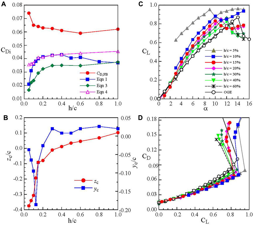
FIGURE 8. Ground effect on (A,B) CDi and vortex flow parameters at α = 10° and x/c = 2.5, and (C,D) CL and CD at Re = 2.71 × 10⁵ (Lu et al., 2019).
The CDi in ground effect was also estimated via
where CL,OGE is the OGE CL value at α = 10o, e is known as the span efficiency representing the non-ellipticity of the spanwise lift distribution and is set at 0.9, AReff (= b′/c) is the effective AR at each h/c, and b′ is the distance between the two vortices. The stationary ground effect was found to produce a higher CL and CD than the OGE case (Figures 8C,D). The CD increase was due to the increase in pressure drag resulting from the ram pressure exerting on the wing’s lower surface and also the flow separation from the wing’s upper surface. At the same CL, the CD was, however, decreased as the stationary ground was approached.
To differentiate the observed discrepancy in the tip vortex flow and lift-induced drag arising from stationary and moving ground conditions, the tip vortex and the associated lift-induced drag of a NACA 0012 rectangular semi-wing in stationary and moving ground effect was investigated by Lu and Lee (2021) in a subsonic wind tunnel by using PIV at Re = 9.2 × 10⁴. The moving ground condition was established by using a moving belt with a surface velocity set at the freestream velocity. They found that the multiple vortex system persisted for h/c > 40% (Figures 7A,B). For h/c ≥ 40%, only the tip vortex appeared. For h/c > 60%, the tip vortex resembled its OGE counterpart. More importantly, for the moving ground the ground vortex was absent (Figure 7B). The secondary vortex persisted regardless of the boundary ground conditions. The appearance of the secondary vortex significantly weakened the tip vortex strength and produced a large induced-drag reduction (Figures 9A,B). The secondary vortex developed over the moving ground produced a higher Γo and CDi than their stationary ground counterpart. The Γo and CDi of the secondary vortex always increased with reducing h/c.
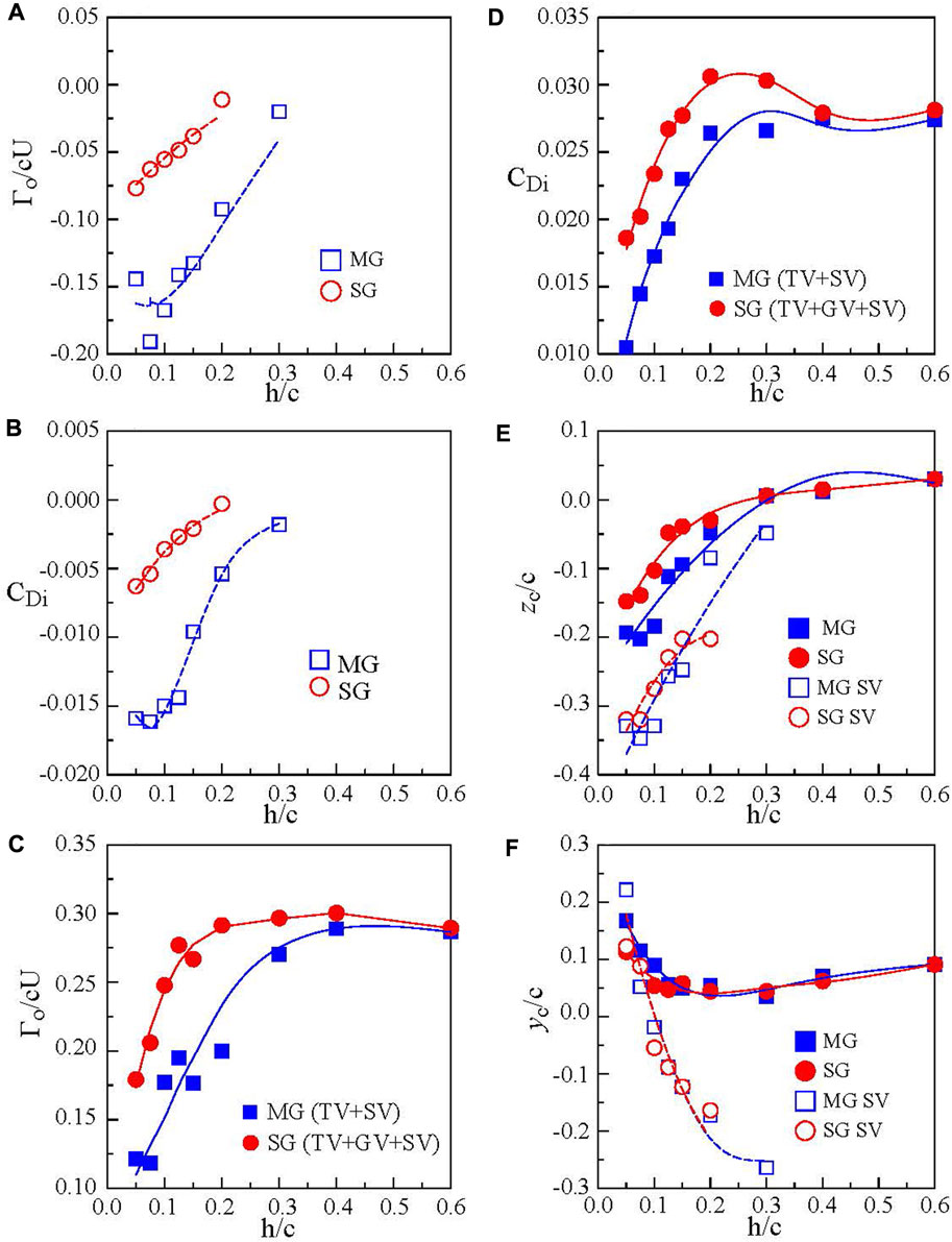
FIGURE 9. Impact of ground effect on (A,B) Γo and CDi of secondary vortex and (C–F) Γo, CDi, and vortex spanwise and vertical location of tip vortex at x/c = 2. MG, SG, TV, and SV denote moving ground, stationary ground, tip vortex, and secondary vortex, respectively (Lu and Lee 2021).
Lu and Lee (2021) also concluded that the combined Γo and CDi of the multiple vortex system also increased slowly with reducing h/c, reaching a sharp local peak, and started to drop rapidly as the ground was further approached (Figures 9C,D). At h/c = 5%, a 57% (or 62%) and 40% (or 32.2%) reduction in the combined Γo for the moving (or stationary) ground relative to the OGE case was observed. The moving ground proximity caused a larger outboard movement of the tip vortex than the stationary ground (Figure 9E). The moving ground effect also produced a larger vortex rebound than the stationary ground effect (Figure 9F). Further downstream, the secondary vortex also rolled around the tip vortex and merged with the tip vortex. In summary, the ground vortex first appeared along the wing’s tip region and continued downstream into the near field. The ground vortex persisted in the spanwise direction along the wing’s leading edge, leading to the formation of the spanwise ground vortex filament (SGVF). The formation of the SGVF along the wing’s leading edge, its downstream development into the ground vortex, and its interaction with the tip vortex and secondary vortex can be better understood by the conceptual sketch depicted in Figure 7C.
3 Reverse or inverted delta wing
Despite the extensive employment of reverse delta wings in the Lippisch-type WIG craft, investigations of the aerodynamics and flow structure of reverse delta wings both outside and in ground effect were scarce (see, Gerhardt (1996), Musaj and Price (2008), Altaf et al. (2011), Wang et al. (2013), Lee and Ko (2016, 2017), Lee and He (2018), Lee et al. (2019), Ko et al. (2020), and Mahgou and Cortelezzi (2020)). In this section, the impact of the ground effect on the aerodynamics and flow structure, especially the trailing vortices, of a slender reverse delta wing was reviewed. Passive control utilizing stand-alone and joint Gurney flap, cropping, and anhedral were also discussed. The aerodynamic and flow field characteristics of the reverse delta wing outside the ground effect (OGE) were also included to serve as a comparison.
3.1 Baseline reverse delta wing
3.1.1 OGE
The aerodynamics and flow behavior of a 75°-sweep reverse delta wing outside the ground effect at Re = 3.82 × 10⁵ were investigated recently by Altaf et al. (2011). Their force balance data show that the slender reverse delta wing produced a lower CL and CD than the delta wing. Also, the trailing vortices possessed a smaller tangential velocity, circulation, and vorticity than the delta wing. Since then, the reverse delta wing has also been employed in the passive control of wingtip-generated vortices by Lee and Su (2012) and Altaf et al. (2016). Lu and Lee (2019) also found that in ground effect the addition of a small tip-mounted half-reverse delta wing led to a rapid diffusion and breakdown of the wingtip vortex, suggesting an effective tip vortex control.
Lee and Ko (2016) and Lee and He (2018) further demonstrated that, in addition to the generation of a lower CL and CD (Figures 10A,B), the 65o-sweep slender reverse delta wing (see Figure 1D) also exhibited a delayed stall at Re = 3.81 × 10⁵ as compared to its delta wing counterpart. For the delta wing, the static-stall angle αss occurred at 34o with CL,max = 1.26 as compared to 38o and 1.175 of the reverse delta wing. The gain in CD reduction of the reverse delta wing overwhelmed the loss in CL, leading to an improved CL/CD ratio as compared to the delta wing (Figure 10C). They also found that, in contrast to the leading-edge vortex (LEV) breakdown-induced stalling of the delta wing (Figures 10D,E), the stalling of the reverse delta wing was triggered by the disruption of the coherent multiple spanwise vortex filaments (SVFs) developed over its upper wing surface (Figures 10F,G). The RDW vortices were originated from the spanwise leading-edge vortex filament. In contrast to the LEV-induced massive flow separation, the disruption of the SVFs over the reverse delta wing was less drastic which resulted in a lowered CD. The LEVs were located inboard and above the delta wing’s upper surface, while the trailing vortices generated by the reverse delta wing were found to be located outside the wing but moved inboard as they progressed downstream.
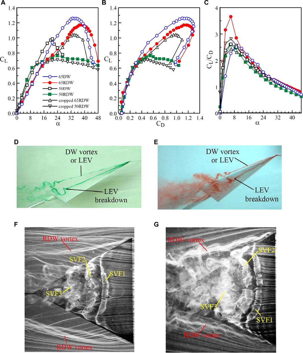
FIGURE 10. (A–C) Aerodynamic coefficients of reverse delta wing (RDW) and regular delta wing (DW) in a free stream. Photos of flow patterns (D–E) DW at α = 19° and 27.5° and (F–G) RDW at α = 14° and 20°. 65RDW and 50RDW denote RDW with 65° and 50° sweep, respectively. SVF denotes spanwise vortex filament. Flow direction is from right to left (Lee and Ko 2016; Lee and He 2018; Lee et al., 2019).
The spatial progression of the iso-ζc/U contours of the RDW trailing vortices and LEVs at selected α were depicted in Figures 11A,B. For clarity, enlarged views of the unique fist-arm pattern of the RDW vortex and the LEV describing their diffusion and breakdown were also given at selected x/c. The RDW vortex had a much lower peak vorticity ζpeak than the delta wing (Figure 12A). At α = 20o, the LEV breakdown occurred between x/c = 0.53 and 0.54 for the delta wing (see Figure 11B). By contrast, the RDW vortex remained concentrated and axisymmetric for α ≤ 16o and became diffused for 16o < α ≤ 23o for x/c > 0.8. For α > 22o, the RDW vortex resembled a circulation-like flow with small patches of vorticity for x/c > 0.3.
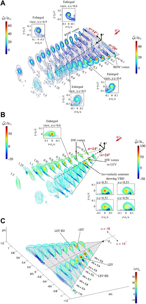
FIGURE 11. Spatial progression of iso-vorticity (ζc/U) contours outside the ground effect. (A) RDW at α = 14° and 20°, (B) slender DW at α = 14° and 24°, and (C) non-slender DW at α = 14° and 16° with Λ = 50° (Lee and Su 2012; Lee and Ko 2016; Lee et al., 2019).
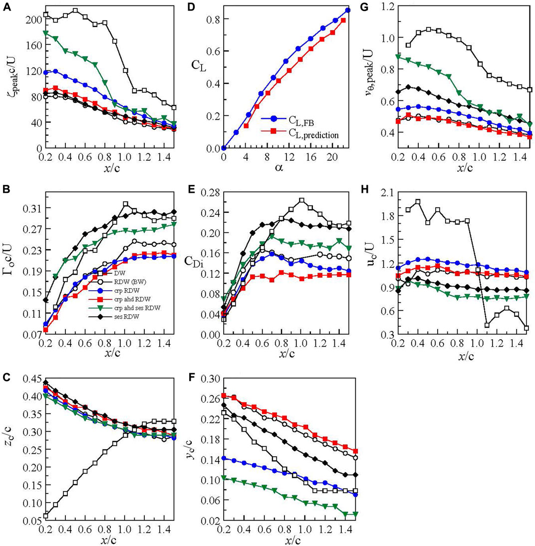
FIGURE 12. (A–C,E–H) Streamwise growth of vortex flow property at α = 16° for Re = 3.81 × 10⁵. (D) CL vs α crp RDW denotes cropped RDW. crp ahd RDW denotes cropped RDW with anhedral. crp ahd ses denotes cropped RDW with anhedral and Gurney flap. ses RDW denotes RDW with Gurney flap (Lee and He 2018).
Lee and He (2018) further reported that the total circulation Γo of the RDW vortex was found to increase with x/c up to x/c > 0.7, attaining an almost constant value (with Γo/cU = 0.241) for 0.7 < x/c < 1.5 (Figure 12B). Also, the trailing-edge apex region covering 0.7 < x/c < 1 was characterized by a 3-D and separated flow (see also Figures 10F,G). The invariant Γo of the RDW vortices for x/c > 1 was also used to predict the CL via the L = ρUΓob′ relationship where b′ = 2zc is the distance between the center of the two trailing vortices (Figure 12C). The CL,predicted = (2Γo/cU) (b′/b) = 0.62 at α = 16o accounted for 94% of CL,FB = 0.661 obtained directly by force balance (Figure 12D), suggesting the strength of the RDW trailing vortices is also a direct indicator of the lift generation of the reverse delta wing. The value of CL,prediction was found to be in good agreement with CL,FB for α ≤ 22°. Meanwhile, the CDi = 0.154 (computed via the Maskell method or Eq. 1) was found to account for 48% of CD,FB = 0.321 (Figure 12E). The vertical movement of the vortices with x/c was displayed in Figure 12F. Both ζpeak and vθ,peak of the RDW vortex were found to increase with x/c, reaching a local maximum at around x/c = 0.5, and began to drop for 0.5 < x/c ≤ 1.5 (Figures 12A,G). The core velocity uc of the RDW vortex was found to be insensitive to x (Figure 12H). The LEV was, however, travelling downstream with a core velocity uc ≈ 2U. The critical LEV flow characteristics at α = 16o were also included Figures 12A–G for reference.
3.1.2 IGE
In ground effect, the CL and CD of the baseline reverse delta wing increased persistently with reducing h/c for h/c < 40% except for the near-stall α regime (Figures 13A,B). The definition of the ground distance h was given in Figure 1E. At a fixed α, the CL increased non-linearly and was the greatest in close ground proximity. The ground proximity, however, caused a slightly earlier wing stall as compared to the OGE case. The stalling mechanism of the reverse delta wing remained virtually unaffected. At a fixed CL, the CD decreased below the baseline-wing value with reducing h/c for h/c ≤ 10%. For h/c > 10%, the CD was larger than the OGE value. Lee and Ko (2018) further reported that the ground proximity also caused a redistribution of the vorticity of the vortex leading to a lowered ζpeak but a higher Γo as compared to its OGE counterpart. The ζpeak reached a local maximum at around x/c = 0.3 and began to drop as it progressed further downstream. The vortex center was displaced further outboard compared to the OGE case but moved slightly away from the wing’s mid-chord as it progressed downstream. The ram pressure, however, produced a higher vθ,peak and Γo than the OGE case. A 37% and 65% increase in vθ,peak and Γo at x/c = 1.01 in ground effect were obtained. In addition, the effective in-ground effect flight of baseline reverse delta wings should be kept within 45%c.
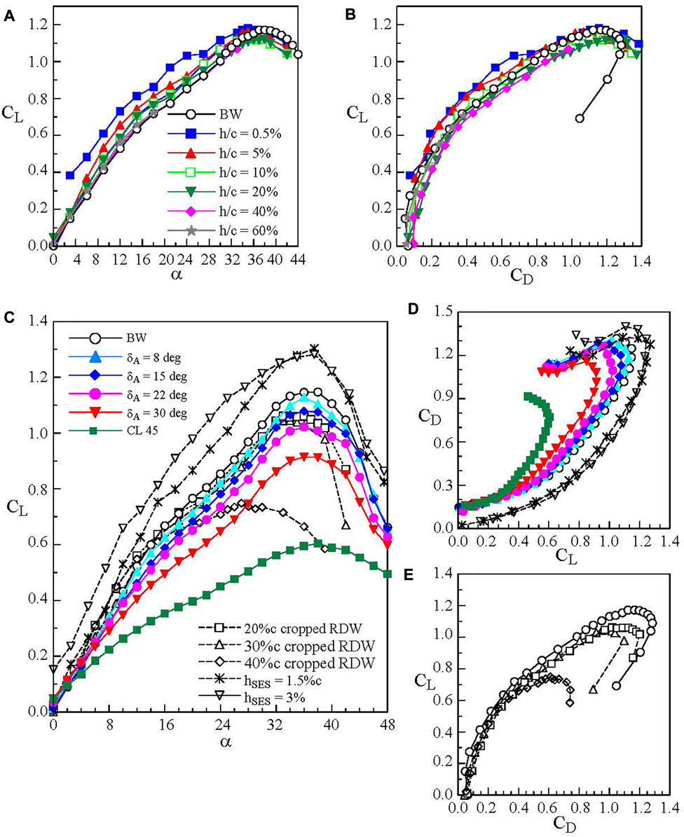
FIGURE 13. (A–B) Ground effect on aerodynamic coefficients of baseline reverse delta wing (BW). (C–E) reverse delta wing with cropping, anhedral, and Gurney flap at Re = 4.06 × 10⁵ outside the ground effect. δA denotes anhedral angle. hSES denotes Gurney flap height (Lee, 2016; Lee et al., 2019).
3.2 Wings with Gurney flap, cropping, and anhedral
To augment the lift generation of the reverse delta wing, passive control using stand-alone and joint Gurney flap, cropping, and anhedral was employed. Figures 1F–H show the schematics of the Gurney flap, cropping, and anhedral and the definition of ground distance h. The Gurney flaps have been employed extensively on conventional wing planforms by researchers elsewhere (see, Wang et al. (2008)). Figures 13C–E show that outside the ground effect the Gurney flap produced a large CL increase because of the reduction of flow leakage from the wing’s trailing edges and, to a much less extent, to the Gurney flap-induced spanwise camber effects. At the same CL, the Gurney flap also produced a smaller CD as compared to the baseline wing (Figure 13D).
Also, since the flow in the trailing apex region of the reverse delta wing is 3-D and is always prone to separate, its removal thereby provides a welcomed weight reduction of the Lippisch-type WIG craft. Figure 1G shows the schematic diagram of the cropped wing. Cropping (up to 40% reduction in the wing’s chord or 16.3% reduction in the wing surface area) in a freestream at Re = 3.81 × 10⁵ was tested by Lee and He (2018). The lift and drag forces were both normalized by the non-cropped baseline-wing surface area SBW. Cropping ≤ 30%c was found to produce a minor change in CL and CD (Figure 13C) as compared to the non-cropped wing. The 30%c cropping was therefore adopted in conjunction with anhedral and Gurney flap. The addition of anhedral (δA = 8° to 45°) gave a decreased CL and CD (Figures 13C,E) due to the anhedral-induced reduction in the wing surface area. The CL decreased rapidly with increasing anhedral angle δA. The trailing vortices were found to move further outboard with an increased vorticity level and tangential velocity with increasing anhedral. Among all the δA tested, the δA = 15° wing anhedral was utilized in the passive control of the reverse delta wing. At a fixed CL, the CD increased with increasing δA. In ground effect the passive control became dramatically beneficial. The cropping allowed the wing to be positioned closer to the ground, causing a persistent increase in the ram pressure and CL, especially for h/c < 20% (Figure 14A). At a fixed CL, the CD was lower (or higher) for h/c ≤ 10% (or h/c > 10%) than the baseline wing (Figure 14B). Also, in contrast to the deteriorated aerodynamic performance associated with the wing anhedral outside the ground effect, the addition of δA to the cropped wing created an almost sealed high-pressure “air tunnel” underneath the wing which significantly increased the value of CL and CD with reducing h/c (Figures 14C,D). The larger the δA was, the larger the CL and CD became. At h/c ≈ 0%, a 270% and 150% ΔCL increment compared to its OGE counterpart for δA = 8° and 45°, respectively, was obtained, which enables the short-distance take-off of the WIG craft.
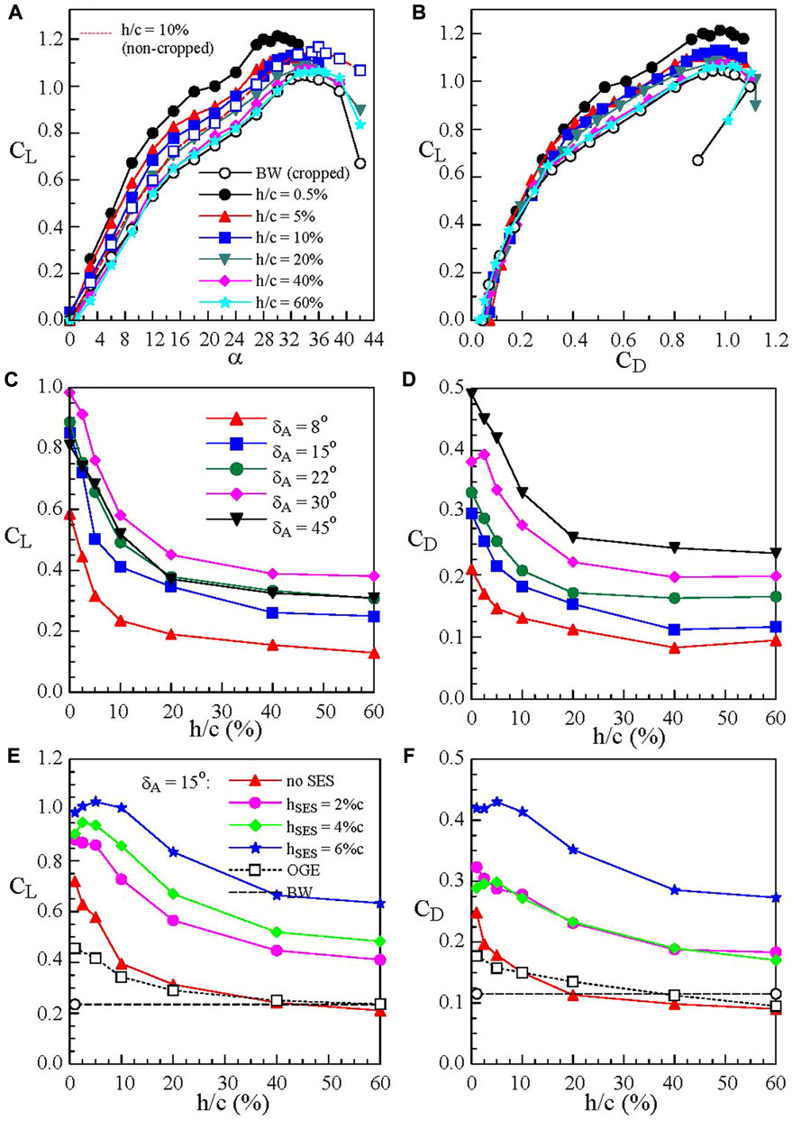
FIGURE 14. Ground effect on the aerodynamic coefficients of 30% cropped reverse delta wing with anhedral and Gurney flaps (Lee and He 2018; Lee et al., 2019).
The anhedral-induced CL augmentation also led to an ever-increasing total circulation of the RDW vortices. The vortices moved further outboard with reducing h/c. The RDW vortices, however, retained their regularity to a higher α with increasing anhedral and reducing h/c. The lift of the cropped and anhedral wing was further increased by the application of the Gurney flap (Figure 14E). The selection of δA = 15° anhedral was based on the configuration of RFB X-114 and AirFish-8. The larger the flap height hSES was, the larger the CL increase became. At h/c = 5%, a 345% and 175% CL increment were attained with hSES = 6%c and 2%c, respectively, as compared to the baseline wing. The CD of the joint configuration increased with reducing h/c and increasing hSES (Figure 14F).
4 Delta wings in ground effect
In this section, the impact of ground effect on the regular delta wing is discussed. The aerodynamics and behavior of the leading-edge vortices (LEVs) of the delta wings in a free stream have been investigated extensively by researchers elsewhere (see, Lowson and Riley (1995), Nelson and Pelletier (2003), and Gursul (2005)). By contrast, the WIG craft utilizing delta wing planforms have received limited attention (Katz and Levin, 1984; Plotkin and Dobele, 1988; Qin et al., 2015; Qu et al., 2015a; Lee and Ko, 2018).
Qu et al. (2015b) found numerically that the CL, CD, and nose-down CM of a slender half-model delta wing at α = 20° and Re = 1.2 × 10⁷ increased with decreasing h/c, and that the ram pressure exerted on the wing’s lower surface contributed to the change in the aerodynamic loads. The ground was set as a no-slip wall condition in their simulation. They also reported that the strength of the LEVs and their axial vorticity and core circulation increased in ground effect. The LEV breakdown, however, occurred earlier as the ground was approached. The large circumferential velocity and the resulted stronger centrifugal force core also led to an expanded LEV core in ground effect.
Lee and Ko (2018) demonstrated experimentally that for a 65°-sweep slender delta wing at Re = 3.81 × 10⁵ both CL and CD increased with reducing h/c (up to 50% of the wing chord, Figures 15A,B). The CL increment was the greatest at low α and decreased rapidly with increasing h/c and α. The ground effect also gave rise to an increased adverse dp/dx gradient, leading to an earlier wing stall and flow separation as compared to their OGE counterpart. In ground effect, the LEVs became stronger and had an higher rotational speed than the OGE case (Figures 15C,D). The smaller the ground distance was, the stronger the LEV and the earlier vortex breakdown became. They also showed that outside the ground effect the LEV breakdown (identified by the sharp drop in ζpeak, the sudden expansion of the vortex size, and the loss of the coherence of the vortex) was found to occur at (x/c) BVD = 0.76 at α = 20°. In ground effect, the (x/c) BVD occurred at 0.71, 0.73, and 0.74 for h/c = 5%, 10%, and 20%, respectively. The LEV breakdown caused a massive flow separation over the wing’s upper surface and, consequently, an ever-increased CD.
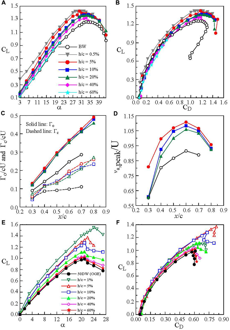
FIGURE 15. Impact of ground effect on (A,B) aerodynamic coefficients of the delta wing and (C,D) LEV flow parameters at α = 20°. (E,F) Non-slender delta wing (Lee and Ko 2018).
For the non-slender delta wing, there was a steeper lift-curve slope accompanied by an earlier stall angle at αss = 21°) as well as a lower CL,max of 0.99 than its slender counterpart with αss = 34° and CL,max = 1.26 (Figure 15E) in a free stream. The LEVs were ill-defined and were located closer to the non-slender delta wing surface (see Figure 11C), leading to a premature LEV breakdown and a lower CL,max and αss as compared to the slender wing. Most of the upper wing surface, however, remained unaffected from the LEV breakdown-caused flow separation, rendering a higher CL for α ≤ αss than the slender wing. At low CL, there was only a marginal change in CD (Figure 15F), regardless of the slenderness and wing planform. In ground effect, the CL and CL,max of the non-slender delta wing increased with reducing h/c for h/c ≤ 40%. The lift-α curve slope increased with reducing h/c. At the same CL, the ground proximity, however, produced a lower CD compared to the OGE case.
In short, the ground proximity leads to strengthened LEVs with an increased circulation, rotational speed, and axial velocity, and, more importantly, an increased lift of the delta wing. The enlargement of the LEVs and ram pressure, however, resulted in a larger drag force as compared to the outside ground effect. The ground effect-induced increase in the adverse pressure gradient inevitably caused an earlier LEV breakdown, leading to unsteady and asymmetric forces and a loss of lift. Control techniques capable of delaying LEV breakdown in ground effect are necessitated in order to make delta wing planforms practical for WIG craft application.
5 Conclusion
5.1 Rectangular wings and airfoils
For the chord-dominated ground effect, there is the appearance of a ground vortex or recirculation region underneath the airfoil’s leading-edge region in close stationary ground effect due to the longitudinal boundary layer developed on the stationary ground surface. The ground vortex leads to a lower lift than its moving-ground counterpart. For the moving ground, the ground vortex is absent. In stationary ground effect, the presence of the longitudinal boundary layer also narrows the flow passage beneath the airfoil, producing a higher lift than the moving ground. The simple stationary ground is applicable by ensuring that the longitudinal boundary layer developed on its surface remains and has an equivalent thickness within 2% of the airfoil chord. The moving ground effect, however, produces a larger wake and drag than the stationary ground effect. For oscillating airfoils, the CDGE leads to a substantial increase in Cl and negative Cm, especially during downstroke. For a static airfoil in non-uniform ground effect, simulated by a simplified sinusoidal wavy ground, there exists a cyclic change in Cl and Cm over an entire wavelength. The cyclic change in Cm is 180°-out-of-phase to the Cl.
For span-dominated ground effect, there exhibits a multiple vortex system, consisting of the tip vortex, co-rotating ground vortex, and counter-rotating secondary vortex behind the finite wing in the close stationary ground effect. The ground vortex adds vorticity to the tip vortex while the secondary vortex negates the vorticity. The ground vortex possesses a much weaker strength than the secondary vortex. In moving ground effect, the ground vortex is absent. The strength of the ground vortex and its interaction with the tip vortex are greatly minimized by using a thin laminar boundary layer developed on the flat ground surface. The moving ground effect also produces a stronger secondary vortex leading to a larger tip vortex rebound and outboard movement, as well as a smaller lift-induced drag and tip vortex strength than their stationary-ground counterpart. The most effective in-ground-effect height or distance for rectangular wings should be within 15% airfoil chord.
To further consolidate the findings, investigations with different moving ground surface velocities are desirable. Moving wavy grounds of different airfoil chord to wavelength ratios and ground distances also demand further investigation. The wavelength and amplitude of the ocean waves can serve as experimental guidelines. The effect of unsteady wings and airfoils subjected to attached-flow, light-stall, and deep-stall heaving and pitching motions, and ramp motions on the aerodynamics and tip vortex, including the lift-induced drag, in both flat and non-uniform ground effects also need further investigation. The heaving and pitching frequency and amplitude should follow that of the ocean waves. Estimation of the lift force as a function of ground distance based on the crossflow or vortical wake flow measurements is also highly desired. Finally, non-rectangular wing planforms in ground effect also merit investigation.
5.2 Reverse delta wings
It is known that the reverse delta wing produces a smaller CL and CD but a delayed wing stall as compared to the regular delta wing. In contrast to the leading-edge vortex breakdown-induced stall of the delta wing, the stalling of the reverse delta wing (RDW) is triggered by the disruption of the multiple spanwise vortex filaments developed over its upper surface. The strength of the outboard-located RDW trailing vortices also shows a direct correlation to the lift generation of the wing. In ground effect, the lift generation of the reverse delta wing increases with reducing ground distance. At a fixed ground distance, the lift increment is the largest in the low−α regime and decreases rapidly and non-linearly with increasing α. The in-ground-effect distance should be less than 40% of the chord of the reverse delta wing. However, the most effective flight height should be within 10% airfoil chord and at low α as well.
The lift generation of the reverse delta wing in ground effect increases significantly by the addition of stand-alone and joint cropping, anhedral, and Gurney flap. In contrast to the outside ground effect, the application of these passive control is always beneficial. A 270% increase in lift of the reverse delta wing is achieved through joint passive control.
Future experiments on static and unsteady reverse delta wings, with and without flow control, subject to individual and joint heaving and pitching motions over moving flat and non-uniform grounds are needed. The wavelength and amplitude of the ocean waves provide experimental guidelines for the pitching and heaving motions. More studies are desired to correlate the strength of the trailing vortices of the wing to its lift generation and lift-induced drag in ground effect. Non-slender reverse delta wings in ground effect also deserve investigation.
For the regular delta wing in ground effect, the lift and strength of the leading-edge vortices increase as compared to the OGE case. The ground proximity, however, causes an earlier leading-edge vortex breakdown as compared to the outside ground effect. Control techniques capable of delaying the ground proximity-caused premature leading-edge breakdown are highly desired to practicalize the application of delta wings in the WIG craft. Investigation of non-slender delta wings in ground effect is also desired. Unsteady delta wings over both flat and non-uniform ground surfaces also deserve consideration.
Author contributions
All authors listed have made a substantial, direct, and intellectual contribution to the work and approved it for publication.
Conflict of interest
The authors declare that the research was conducted in the absence of any commercial or financial relationships that could be construed as a potential conflict of interest.
Publisher’s note
All claims expressed in this article are solely those of the authors and do not necessarily represent those of their affiliated organizations, or those of the publisher, the editors, and the reviewers. Any product that may be evaluated in this article, or claim that may be made by its manufacturer, is not guaranteed or endorsed by the publisher.
Footnotes
1Lin, G., and Lee, T. (2022). Lift computation through crossflow measurement behind a rectangular semi-wing in ground effect. J. Fluids Eng. Submitted manuscript.
References
Ahmed, M. R., and Sharma, S. D. (2005). An investigation on the aerodynamics of a symmetrical airfoil in ground effect. Exp. Therm. Fluid Sci. 29 (6), 633–647. doi:10.1016/j.expthermflusci.2004.09.001
Ahmed, M. R., Takasaki, T., and Kohama, Y. (2007). Aerodynamics of a NACA 4412 airfoil in ground effect. AIAA J. 45 (1), 37–47. doi:10.2514/1.23872
Altaf, A., Omar, A. A., Asrar, W., and Jamaluddin, H. B. L. (2011). Study of the reverse delta wing. J. Aircr. 48 (1), 277–286. doi:10.2514/1.c031101
Altaf, A., Thong, T. B., Omar, A. A., and Asrar, W. (2016). Influence of a reverse delta-type add-on device on wake vortex alleviation. AIAA J. 54 (2), 625–636. doi:10.2514/1.j054436
Ando, S., Sakai, T., and Nitta, K. (1992). Analysis of motion of airfoil flying over wavy-wall surface. Jpn. Soc. Aeronautics Space Sci. Transaction 35 (107), 27–38.
Barber, T. J., Leonardi, E., and Archer, R. D. (2002). Causes for discrepancies in ground effect analyses. Aeronautical J., 653–667. doi:10.1017/S0001924000011726
Breitsamter, C., and Allen, A. (2009). Transport aircraft wake influenced by oscillating winglet flaps. J. Aircr. 46 (1), 175–188. doi:10.2514/1.37307
Brune, G. W. (1994). Quantitative low-speed wake surveys. J. Aircr. 31 (2), 249–255. doi:10.2514/3.46481
Carter, A. (1961). Effect of ground proximity on the aerodynamic characteristics of aspect ratio-1 airfoils with and without end plates, 970. Washington, D.C., United States: NASA.
Chow, J. S., Zilliac, G. G., and Bradshaw, P. (1997). Mean and turbulence measurements in the near field of a wingtip vortex. AIAA J. 35 (10), 1561–1567. doi:10.2514/3.13712
Chun, H., Park, I., Chung, K., and Shin, M. (1996). Computational and experimental studies on wings in ground effect and a WIG effect craft. in editor: L. J. Prandolini Workshop proceedings of Ekranoplans and very fast craft, (Kensington, Australia: University of New South Wales), 5 December, 38–60.
Corjon, A., and Poinsot, T. (1997). Behavior of wake vortices near ground. AIAA J. 35 (2), 849–855. doi:10.2514/3.13598
Coulliette, C., and Plotkin, A. (1995). “Airfoil ground effect revisited,” in AIAA Paper, San Diego,CA,U.S.A, June 19–22, 1995.
Devenport, W. J., Rife, M. C., Liapis, S. I., and Follin, G. J. (1996). The structure and development of a wing-tip vortex. J. Fluid Mech. 312, 67–106. doi:10.1017/s0022112096001929
Duraisamy, K., and Baeder, J. D. (2003). “Control of tip vortex structure using steady and oscillatory blowing,” in AIAA Paper, Orlando, Florida, June 23–26, 2003.
Gerhardt, H. A. (1996). Supersonic natural laminar flow wing. U.S. Patent Application No. US005538201A.
Gerontakos, P., and Lee, T. (2007). Lift-induced drag of a cambered wing for Re ≤ 1 × 10⁶. Exp. Fluids 42, 363–369. doi:10.1007/s00348-006-0242-6
Ghadimi, P., Rostami, A. B., and Jafarkazemi, F. (2012). Aerodynamic analysis of the boundary layer region of symmetric airfoils at ground proximity. Aerosp. Sci. Technol. 17 (1), 7–20. doi:10.1016/j.ast.2011.02.008
Greenblatt, D. (2012). Fluidic control of a wing tip vortex. AIAA J. 50 (2), 375–386. doi:10.2514/1.j051123
Greenblatt, D., Vey, S., Paschereit, O. C., and Meyer, R. (2009). Flap vortex management using active Gurney flaps. AIAA J. 47 (2), 2845–2856. doi:10.2514/1.41767
Gross, J., and Traub, L. W. (2012). Experimental and theoretical investigation of ground effect at low Reynolds numbers. J. Aircr. 49 (2), 576–586. doi:10.2514/1.c031595
Gursul, I. (2005). Review of unsteady vortex flows over slender delta wings. J. Aircr. 42 (2), 299–319. doi:10.2514/1.5269
Halloran, M., and Sean O’Meara, S. (1999). Wing in ground effect craft review. Melbourne, Australia: Defense Science and Technology Organization.
Han, C., and Choi, J. (2005). Unsteady trailing vortex evolution behind a wing in ground effect. J. Aircr. 42 (2), 429–434. doi:10.2514/1.6477
Han, C., and Kinnas, S. (2013). Study on the wake shape behind a wing in ground effect using an unsteady discrete vortex panel method. Open J. Fluid Dyn. 3, 261–265. doi:10.4236/ojfd.2013.34032
Harvey, J. K., and Perry, F. J. (1971). Flowfield produced by trailing vortices in the vicinity of the ground. AIAA J. 9 (8), 1659–1660. doi:10.2514/3.6415
Hasebe, H., Naka, Y., and Fukagata, K. (2011). An attempt for suppression of wing-tip vortex using plasma actuators. J. Fluid Sci. Technol. 6 (6), 976–988. doi:10.1299/jfst.6.976
Hayashi, M., and Endo, E. (1978). Measurement of flowfield around an airfoil section with separation. Jpn. Soc. Aeronautics Space Sci. Trans. 21 (52), 69–75.
He, W., Guan, Y., Theofilis, V., and Li, L. K. B. (2019). Stability of low-Reynolds-number separated flow around an airfoil near a wavy ground. AIAA J. 57 (1), 29–34. doi:10.2514/1.j057544
He, W., Yu, P., and Li, L. (2018). Ground effects on the stability of separated flow around a NACA 4415 airfoil at low Reynolds numbers. Aerosp. Sci. Technol. 72, 63–76. doi:10.1016/j.ast.2017.10.039
Holzapfel, F., and Steen, M. (2007). Aircraft wake-vortex evolution in ground proximity: Analysis and parameterization. AIAA J. 45 (1), 218–227. doi:10.2514/1.23917
Hsiun, C. M., and Chen, C. K. (1996). Aerodynamic characteristics of a two-dimensional airfoil with ground effect. J. Aircr. 33 (2), 386–392. doi:10.2514/3.46949
Im, Y.-H., and Chang, K.-S. (2000). Unsteady aerodynamics of a wing-in-ground-effect airfoil flying over a wavy wall. J. Aircr. 37 (4), 690–696. doi:10.2514/2.2653
Joh, C. Y., and Kim, Y. J. (2004). Computational aerodynamic analysis of airfoil for WIG (wing-in-ground effect) craft. Jpn. Korean Soc. Aeronautical Space Sci. 32 (8), 37–46. doi:10.5139/JKSAS.2004.32.8.037
Katz, J., and Levin, D. (1984). Measurements of ground effect for delta wings. J. Aircr. 21, 441–443. doi:10.2514/3.44988
Ko, L. S., Tremblay-Dionne, V., and Lee, T. (2020). Impact of ground proximity on an inverted delta wing. J. Aerosp. Eng. 33 (5), 1–8. doi:10.1061/(asce)as.1943-5525.0001163
Kusunose, K. (1998). Drag reduction based on a wake-integral method. Reston, Virginia, United States: AIAA. 98-2723.
Lee, J., Han, C.-S., and Bae, C.-H. (2010). Influence of wing configurations on aerodynamic characteristics of wings in ground effect. J. Aircr. 47 (3), 1030–1040. doi:10.2514/1.46703
Lee, T., and Choi, S. (2015). Wingtip vortex control via tip-mounted half-delta wings of different geometric configurations. J. Fluids Eng. 137 (12), 1–9. doi:10.1115/1.4030852
Lee, T., and He, S. M. (2018). The trailing vortices generated by a reverse delta wing with different wing configurations. Aerosp. Sci. Technol. 82-83, 378–393. doi:10.1016/j.ast.2018.08.022
Lee, T., Huitema, D., and Leite, P. (2019). Ground effect on a cropped slender reverse delta wing with anhedral and Gurney flaplike side-edge strips. Proc. Institution Mech. Eng. Part G J. Aerosp. Eng. 233 (7), 2433–2444. doi:10.1177/0954410018779504
Lee, T., and Ko, L. S. (2016). Experimental study of the vortex flow and aerodynamic characteristics of a reverse delta wing. Proc. Institution Mech. Eng. Part G J. Aerosp. Eng. 230 (6), 1126–1138. doi:10.1177/0954410015604653
Lee, T., and Ko, L. S. (2018). Ground effect on the vortex flow and aerodynamics of a slender delta wing. J. Fluids Eng. 140, 1–9. doi:10.1115/1.4039232
Lee, T., and Ko, L. S. (2017). Vortex flow and lift generation of a non-slender reverse delta wing. Proc. Institution Mech. Eng. Part G J. Aerosp. Eng. 231 (13), 2438–2451. doi:10.1177/0954410016671342
Lee, T., Majeed, A., Siddiqui, B., and Tremblay-Dionne, V. (2018). Impact of ground proximity on the aerodynamic properties of an unsteady airfoil. Proc. Institution Mech. Eng. Part G J. Aerosp. Eng. 232 (10), 1814–1830. doi:10.1177/0954410017703416
Lee, T., and Su, Y. Y. (2015). Surface pressures developed on an airfoil undergoing heaving and pitching motion. J. Fluids Eng. 137 (5), 1–11. doi:10.1115/1.4029443
Lee, T. (2016). Impact of Gurney flap-like strips on the aerodynamic and vortex flow characteristic of a reverse delta wing J. Fluids Eng. 138 (6), 1–8. doi:10.1115/1.4032301
Lee, T., and Su, Y. Y. (2012). Wingtip vortex control via the use of a reverse half-delta wing. Exp. Fluids 52 (6), 1593–1609. doi:10.1007/s00348-012-1274-8
Lee, T., and Tremblay-Dionne, V. (2018). Experimental investigation of the aerodynamics and flowfield of a NACA 0015 airfoil over a wavy ground. J. Fluids Eng. 140 (7), 1–10. doi:10.1115/1.4039236
Lee, T., Tremblay-Dionne, V., and Ko, L. S. (2019). Ground effect on a slender reverse delta wing with anhedral. Proc. Institution Mech. Eng. Part G J. Aerosp. Eng. 233 (4), 1516–1525. doi:10.1177/0954410017754147
Lowson, M. V., and Riley, A. J. (1995). Vortex breakdown control by delta wing geometry. J. Aircr. 32 (4), 832–838. doi:10.2514/3.46798
Lu, A., and Lee, T. (2021). Effect of ground boundary condition on near-field wingtip vortex flow and lift-induced drag. J. Fluids Eng. 143 (3), 1–12. doi:10.1115/1.4048875
Lu, A., and Lee, T. (2019). Passive wingtip vortex control by using small tip-mounted half delta wings in ground effect. J. Fluids Eng. 142 (2), 1–13. doi:10.1115/1.4044669
Lu, A., Tremblay-Dionne, V., and Lee, T. (2019). Experimental study of aerodynamics and wingtip vortex of a rectangular wing in ground effect. J. Fluids Eng. 141, 1–11. doi:10.1115/1.4043593
Luo, S. C., and Chen, Y. S. (2012). Ground effect on flow past a wing with a NACA 0015 cross-section. Exp. Therm. Fluid Sci. 40, 18–28. doi:10.1016/j.expthermflusci.2012.01.014
Mahgou, A. O., and Cortelezzi, L. (2020). Vortex flow and aerodynamic performance of a reverse delta wing. AIAA J. 58 (2), 537–549. doi:10.2514/1.j058021
Mantle, P. J. (2016). Induced drag of wings in ground effect. Aeronaut. J. 120 (1234), 1867–1890. doi:10.1017/aer.2016.106
Maskell, E. (1973). Progress towards a method for the measurement of the components of the drag of a wing of finite span. Madrid, Spain: RAE. Technical Report 72232.
Matalanis, C. G., and Eaton, J. K. (2007). Wake vortex control using static segmented Gurney flaps. AIAA J. 45 (2), 321–328. doi:10.2514/1.25956
Matveev, K. I. (2015). Heave and pitch motions of wing-in-ground craft flying above wavy surface. Front. Aerosp. Eng. 4 (2), 43–48. doi:10.12783/fae.2015.0402.01
Mondal, P., and Balakrishnan, N. (2014). Discrete vortex method-based model for ground-effect studies. AIAA J. 52 (12), 2817–2828. doi:10.2514/1.j052920
Mondal, P. (2015). Prediction of moment using a modified discrete vortex method in ground effect. Def. Sci. J. 71 (2), 146–152. doi:10.14429/dsj.71.16127
Moore, N., Wilson, P. A., and Peters, A. J. (2002). “An investigation into wing in ground effect airfoil geometry,” in RTO-MP-095 SCI symposium on challenges in dynamics, system identification, control and handling qualities for land, air, Sea and space vehicles (France: NATO RTO), 11–30.
Morishita, E., and Ashihara, K. (1995). Ground effect calculation of a two-dimensional airfoil over a wavy surface. Jpn. Soc. Aeronautics Space Sci. 38, 77–90.
Musaj, M., and Price, S. A. (2008). “Numerical and experimental investigation of the aerodynamics of an unconventional W-leading edge reversed delta wing in ground effect,” in 26th International Congress of the Aeronautical Science (ICAS), Alaska, USA, 14-19 September 2008.
Nelson, R. C., and Pelletier, A. (2003). The unsteady aerodynamics of slender wings and aircraft undergoing large amplitude maneuvers. Prog. Aerosp. Sci. 39, 185–248. doi:10.1016/s0376-0421(02)00088-x
Plotkin, A., and Dobele, S. S. (1988). Slender wing in ground effect. AIAA J. 26 (4), 493–494. doi:10.2514/3.9920
Plotkin, A., and Kennel, C. G. (1981). Thickness-induced lift on a thin airfoil in ground effect. AIAA J. 19 (11), 1484–1486. doi:10.2514/3.7880
Puel, P., and Victor, X. D. S. (2000). Interaction of wake vortices with the ground. Aerosp. Sci. Technol. 4, 239–247. doi:10.1016/s1270-9638(00)00139-5
Qin, Y., Qua, Q., Liua, P., Yun, T., and Lub, Z. (2015). DDES study of the aerodynamic forces and flow physics of a delta wing in static ground effect. Aerosp. Sci. Technol. 43, 423–436. doi:10.1016/j.ast.2015.04.004
Qu, Q., Lu, Z., Guo, H., Liu, P., and Agarwal, R. K. (2015b). Numerical investigation of the aerodynamics of a delta wing in ground effect. J. Aircr. 52 (1), 329–340. doi:10.2514/1.c032735
Qu, Q., Lu, Z., Liu, P., and Agarwal, R. K. (2014). Numerical study of aerodynamics of a wing-in-ground-effect craft. J. Aircr. 51, 913–924. doi:10.2514/1.c032531
Qu, Q., Wang, W., Liu, P., and Agarwal, R. K. (2015a). Airfoil aerodynamics in ground effect for wide range of angles of attack. AIAA J. 53 (4), 1048–1061. doi:10.2514/1.J053366
Ramaprian, B. R., and Zheng, Y. (1997). Measurements in rollup region of the tip vortex from a rectangular wing. AIAA J. 35 (12), 1837–1843. doi:10.2514/3.13759
Rozhdestvensky, K. V. (2006). Wing-in-ground effect vehicles. Prog. Aerosp. Sci. 42 (3), 211–283. doi:10.1016/j.paerosci.2006.10.001
Spalart, P. R. (1998). Airplane trailing vortices. Annu. Rev. Fluid Mech. 30, 107–138. doi:10.1146/annurev.fluid.30.1.107
Steinbach, D. (1997). Comment on aerodynamic characteristics of a two-dimensional airfoil with ground effect. J. Aircr. 34 (2), 455–456. doi:10.2514/2.2195
Suh, Y. B., and Ostowari, C. (1988). Drag reduction factor due to ground effect. J. Aircr. 25 (11), 1071–1072. doi:10.2514/3.45705
Tomaru, H., and Kohama, Y. (1990). “Experiments on wing in ground effect with fixed ground plates,” in Proceedings of the 2nd JSME-KSME fluids eng. Conference (Tokyo: Japan Society of Mechanical Engineers), 370–373.
Tremblay-Dionne, V., and Lee, T. (2021). Discrepancy in the aerodynamics and flowfield of a symmetric airfoil produced by the stationary and moving ground effect. J. Fluids Eng. 143 (2), 1–10. doi:10.1115/1.4048290
Tremblay-Dionne, V., and Lee, T. (2019). Effect of trailing-edge flap deflection on a symmetric airfoil over a wavy ground J. Fluids Eng. 141 (6), 1–4. doi:10.1115/1.4041736
Tremblay-Dionne, V., and Lee, T. (2019). Experimental study on effect of wavelength and amplitude of wavy ground on a NACA 0012 airfoil. J. Aerosp. Eng. 32 (5), 1–8. doi:10.1061/(asce)as.1943-5525.0001051
Tuck, E., and Standingford, D. (1996). “Lifting surface in ground effect,” in Workshop proceedings of Ekranoplans and very fast craft at the University of New South Wales, Australia, December 5, 1996, 230–243.
Turner, T. R. (1966). Endless-belt technique for ground simulation. Washington, D.C., United States: NASA. SP-116.
Wang, H., Teo, C. J., Khoo, B. C., and Goh, C. J. (2013). Computational aerodynamics and flight stability of wing-in-ground (WIG) craft. Procedia Eng. 67, 15–24. doi:10.1016/j.proeng.2013.12.002
Wang, J. J., Li, Y. C., and Choi, K. S. (2008). Gurney flap-lift enhancement, mechanisms and applications. Prog. Aerosp. Sci. 44 (1), 22–47. doi:10.1016/j.paerosci.2007.10.001
Yun, L., Bliault, A., and Doo, J. (2010). WIG craft and Ekranoplan: Ground effect craft technology. New York: Springer.
Nomenclature
a Wave amplitude
b Wingspan
b′ Distance between the core of two vortices
c Airfoil or wing chord
CD Total drag coefficient
CD,FB CD measured with force balance
Cd Sectional drag coefficient
CDi Lift-induced drag coefficient
Cl Sectional lift coefficient
CL Total lift coefficient
CL,FB CL measured with force balance
Cm Pitch-moment coefficient
Cp Surface pressure coefficient
Di Lift-induced drag
f Oscillation frequency in Hz
h Ground distance
hSES Gurney flap height
Re Chord Reynolds number, = Uc/ν
U Freestream velocity, = u∞
uc Vortex core axial velocity
v,w Vertical and spanwise velocity
vθ Tangential velocity
x,y,z Streamwise, vertical, and spanwise direction
yc,zc Vertical and spanwise vortex center
α Angle of attack
δA Wing anhedral
κ Reduced frequency, = πfc/U
λ Wavelength
Λ Sweep angle
ζ Streamwise vorticity
ζpeak Peak ζ
Γ Circulation
Γb,m Root bound circulation measured at the root (z = 0)
Γc Core circulation
Γo Total circulation
ν Kinematic viscosity
Abbreviation
BA Baseline airfoil
BW Baseline wing
CDGE Chord-dominated ground effect
DW Delta wing
GEV Ground-effect vehicle
GV Ground vortex
HDW Half-delta wing
IGE In ground effect
LEV Leading-edge vortex
MG Moving ground
MV Main vortex
OGE Outside ground effect
PIV Particle image velocimetry
RDW Reverse delta wing
SDGE Span-dominated ground effect
SG Stationary ground
SGVF Spanwise ground vortex filament
SLV Shear-layer vortex
SV Secondary vortex
SVF Spanwise vortex filament
TV Tip vortex
WIG Wing-in-ground effect
Keywords: lift, lift-induced drag, ground effect, reverse delta wing, aerodynamics
Citation: Lee T and Lin G (2022) Review of experimental investigations of wings in ground effect at low Reynolds numbers. Front. Aerosp. Eng. 1:975158. doi: 10.3389/fpace.2022.975158
Received: 21 June 2022; Accepted: 23 September 2022;
Published: 15 November 2022.
Edited by:
Lance Traub, Embry Riddle Aeronautical University, United StatesReviewed by:
Geoffrey Spedding, University of Southern California, United StatesDoug Hunsaker, Utah State University, United States
Copyright © 2022 Lee and Lin. This is an open-access article distributed under the terms of the Creative Commons Attribution License (CC BY). The use, distribution or reproduction in other forums is permitted, provided the original author(s) and the copyright owner(s) are credited and that the original publication in this journal is cited, in accordance with accepted academic practice. No use, distribution or reproduction is permitted which does not comply with these terms.
*Correspondence: T. Lee, dGltLmxlZUBtY2dpbGwuY2E=