 Joshua Cooper1*
 Jayakrishnan Vijayamohanan
- 1Electrical and Computer Engineering, University of New Mexico, Albuquerque, NM, United States
- 2Air Force Research Laboratory, Space Vehicles Directorate Kirtland AFB, Albuquerque, NM, United States
A new design for a reconfigurable polarizer integrated E band horn antenna is proposed in this paper. The reconfigurable polarizer consists of two septum based waveguides which can be arranged in different configurations. Depending on the orientation of the waveguides relative to each other the desired polarization can be achieved among Linear, Right-handed circular and Left-handed circular polarization. The polarizer is integrated with a horn antenna and optimized to work from 60 to 90 GHz. This antenna is fabricated, and measured for different frequencies. The proposed design has a line of sight Axial Ratio (AR) around 1 dB and a 3 dB AR beamwidth of 56O at the center frequency.
1 Introduction
Polarization reconfigurability is a desirable trait in most modern communication systems (Balanis, 2005; Choudhury, 2023). However, there are many different applications where the antenna choice is fixed, such as using a horn antenna or any other waveguide-fed transmitter. In such cases, including a reconfigurable waveguide polarizer to the antenna would be necessary to attain polarization diversity. As modern communication systems move towards millimeter wave technologies to make use of their higher data rates and lower latencies, there is an imperative need to attain polarization diversity in these bands to provide robust solutions (Xiao et al., 2017).
The oldest approach in literature dealing with an agile polarizer in E band would be the meandering line polarizer (Zürcher, 1998). Other approaches include using periodic structures such as equally spaced dielectric gaps, circular cavities, cross slots, etc.,; but these do not cover all polarizations in the same device (Ayoub et al., 2022; Dietlein et al., 2007). Using a lens to change the polarization is a very attractive alternative (Poyanco et al., 2023; Melendro-Jimenez et al., 2023), however these designs may affect the efficiency and directivity of the antenna. Also, these ideas require an additional structure to be mounted on top of the antenna, which may not always be possible. Polarization flexibility at lower frequencies can easily be achieved with the use of pin diodes, varactors, MEMS switches, or even mechanical methods in the antenna design/feeding circuit to have it radiate in circular or linear polarization (Patriotis et al., 2021; Cheng and Dong, 2021; Chen et al., 2019). However, these approaches cannot be implemented at higher frequencies. At these frequencies there has been one recent demonstration to electronically attain polarization change using Liquid Crystals (LC) (Doumanis et al., 2014). However, LC devices may not always be practical and can be difficult to implement.
In this paper, we propose a novel waveguide polarizer which can be reconfigured before application to attain one out of three polarizations for each test case - linear polarization (LP), Right handed circular polarization (RHCP), or Left handed circular polarization (LHCP). To demonstrate the functioning of this reconfigurable polarizer we integrate it to the feed of an E-band horn antenna and characterize it. The different components of the polarizer are shown in Figure 1.
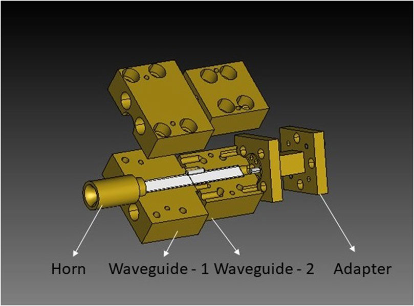
Figure 1. The different components of the proposed polarizer integrated horn antenna. The upper half of the polarizer has been removed to display the dielectric septum inside it.
To attain the polarization conversion one can use a septum based partition in the waveguide. Dielectric loading using a septum has already been shown to induce CP in (Wang et al., 2004). Using the same principle, a stepped septum polarizer was developed in (Chen and Tsandoulas, 1973), and later used to polarize a horn (Franco, 2011), and even used to create a duplexer at 225 GHz (Leal-Sevillano et al., 2013). We expand on this approach by adding another similar dielectric film in the feeding waveguide. Thus, depending on how the two dielectric films are arranged, we can have six different orientations, as seen in Figure 2. By using smart fabrication techniques, we integrate a low-gain horn antenna to this design so that the dielectric films forming the septum can be arranged in multiple ways to generate reconfigurablity in terms of the polarization of the horn. The key advantage offered by our work is that the working principle of this design can be extended and applied to any waveguide-fed antenna. It would also be possible to include elliptical polarization by creating new alignment positions of the septum within the waveguide structure. A similar advantage is offered in (Farzami et al., 2018), but uses pin diodes and hence can only operate in lower frequencies. Since our design makes use of a septum to control the polarization of the transmitted wave, it constrained at the higher frequencies by the smallest dimensions at which the septum can be created. Thus, in this way, we introduce a novel reconfigurable horn antenna which depending on how it is assembled, can radiate with LP, RHCP, or LHCP.
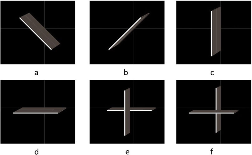
Figure 2. All six possible different configurations of the proposed polarizer. Configuration (a) results in a RHCP wave, and (b) results in a LHCP wave. Rest of the configurations (c–f) result in a linear wave.
2 Materials and methods
The antenna has four parts; the horn antenna, two waveguides consisting of a septum in the middle forming the polarizer, and an adapter. These are all assembled as shown in Figure 1.
2.1 Polarizer
The septum is created by a thin film of Polytetrafluoroethylene (PTFE) inserted in two of the slots of thickness
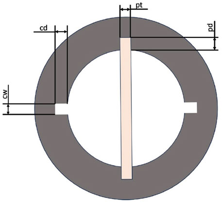
Figure 3. Cross sectional view of the polarizer.

Table 1. Dimensions involved in the polarizer (in mm).
The default configuration of the polarizer is shown in Figure 2a, where both septums are making an angle of 45° to the horizontal plane of the waveguide. This results in the horn getting fed with a RHCP wave. Similarly, if they are aligned at an angle of −45° (Figure 2b), it results in a LHCP wave. If they are both parallel to the waveguide, or perpendicular to each other, as in Figure 2c–f, then the linearly polarized wave continues to propagate and is fed to the horn. The septum controlling the orthogonalization of the E fields is well studied and has already been described in (Wang et al., 2004). The length of the septum changes the phase difference between the orthogonal modes, and thus this parameter
Figure 4. Electric field distribution on the septum. These fields combine with the remaining fields within the waveguide to create the CP pattern for the attached horn.
2.2 Horn antenna
A horn antenna is selected to be included with the polarizer. The horn antenna is created by designing an exponential taper between the diameter of the polarizer
The adapter is a standard WR-12 circular waveguide that has UG-387 flanges on both sides. The antenna is fabricated on a CNC machine and assembled for experimental verification.
To verify the polarization of the proposed antenna system, the Axial Ratio (AR) was also calculated for the waveguide along with the horn antenna. Figure 5 shows the AR at 75 and 90 GHz as a function of theta. We here see that there exists an AR
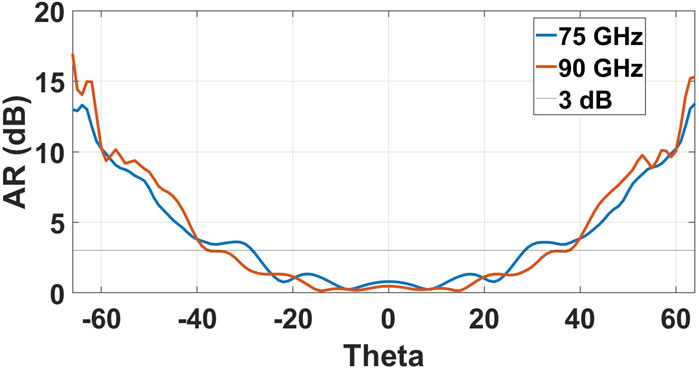
Figure 5. Axial ratio simulations as a function of theta for
3 Results
We first test for the
Figure 6.
Next, the radiation pattern of the polarizer integrated horn antenna is measured using a spherical near field measurement chamber. The measurement setup is shown in Figure 7. The radiation pattern for config-a is shown in Figure 8 for 75 and 90 GHz. We see here that there is one main lobe for the RHCP configurations, keeping an isolation of around 10 dB with the cross-polarization measurements. We also plot the simulations and see good similarities for the co-pol measurement. The cross polarization beam measurements seem to differ from the simulations, especially in terms of a significant decrease in the backlobe. The cross polarization measurements also indicate a narrow main lobe as compared to the simulations.
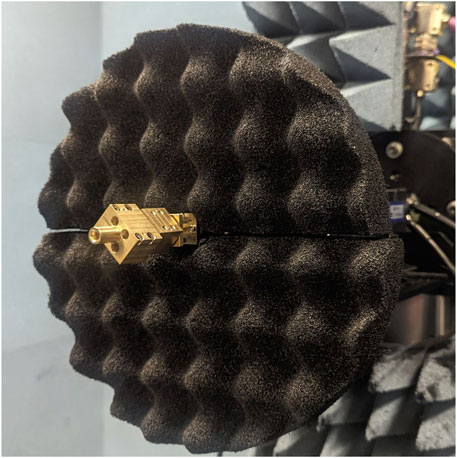
Figure 7. Measurment setup of the antenna. The polarizer is set to operate in the RHCP mode here.
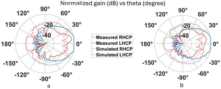
Figure 8. Radiation pattern measurements (normalized gain (dB) v/s theta (degree)) for RHCP configuration. The planes are for
The radiation patterns for the linear configuration are shown in Figure 9. Again, the co pol measurements are in good agreement with the simulations. There is isolation of 20 dB at 75 GHz and 10 dB at 90 GHz, but the cross pol pattern is slightly different from the simulations. While the cross polarization measurement is narrower than the simulation at 75 GHz, it becomes wider at 90 GHz. This consistent anomaly for the cross polarization measurement could indicate that certain small bends in the septum while fabricating and assembling might be causing these differences. More precise fabrication and assembling of the polarizer may improve the cross polarization pattern. A more suitable choice of dielectric material for a sturdy septum may also improve the accuracy of assembly.
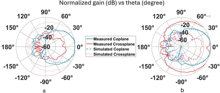
Figure 9. Radiation pattern measurements (normalized gain (dB) v/s theta (degree)) for linear configuration. The planes are for
All the configurations generate a dominant main lobe with a half power beamwidth around 48° at 75 GHz. This value steadily declines to around 36° at 90 GHz. Small sidelobes exist in certain patterns but these are around 25–30 dB below the mainlobe.
4 Conclusion
A novel reconfigurable polarizer integrated horn antenna is proposed in this paper. The polarizer works on the principle of a septum made of two dielectric films causing a phase shift in the propagating orthogonal E fields. The design is made in such a way that the two waveguides containing the septum can be oriented in multiple ways. Depending on the orientation of the adjoining waveguides a linear wave can be kept the same, or converted to LHCP or RHCP. A possible drawback of the proposed antenna would be the difficulty in the waveguide assembly. The septum is very delicate and the antenna performance is sensitive to imprecise manufacturing. The proposed antenna can easily be included in any waveguide fed design and can also be scaled to radiate the desired polarization at any frequency.
Data availability statement
The original contributions presented in the study are included in the article/supplementary material, further inquiries can be directed to the corresponding author.
Author contributions
JC: Data curation, Conceptualization, Visualization, Formal Analysis, Investigation, Writing – review and editing, Methodology, Software. JV: Investigation, Validation, Visualization, Supervision, Formal Analysis, Writing – original draft. EA: Resources, Writing – review and editing, Methodology, Project administration, Supervision. SL: Validation, Resources, Project administration, Writing – review and editing, Supervision, Funding acquisition. CC: Visualization, Formal Analysis, Resources, Funding acquisition, Conceptualization, Project administration, Writing – review and editing, Supervision, Validation.
Funding
The author(s) declare that no financial support was received for the research and/or publication of this article.
Conflict of interest
The authors declare that the research was conducted in the absence of any commercial or financial relationships that could be construed as a potential conflict of interest.
Generative AI statement
The author(s) declare that no Generative AI was used in the creation of this manuscript.
Publisher’s note
All claims expressed in this article are solely those of the authors and do not necessarily represent those of their affiliated organizations, or those of the publisher, the editors and the reviewers. Any product that may be evaluated in this article, or claim that may be made by its manufacturer, is not guaranteed or endorsed by the publisher.
References
Ayoub, F. N., Tawk, Y., Ardelean, E., Costantine, J., Lane, S. A., and Christodoulou, C. G. (2022). Cross-slotted waveguide array with dual circularly polarized radiation at w-band. IEEE Trans. Antennas Propag. 70, 268–277. doi:10.1109/TAP.2021.3090863
Chen, M., and Tsandoulas, G. (1973). A wide-band square-waveguide array polarizer. IEEE Trans. Antennas Propag. 21, 389–391. doi:10.1109/TAP.1973.1140486
Chen, Z., Wong, H., and Liu, Y. (2019). A polarizer integrated dielectric resonator antenna for polarization reconfigurability. IEEE Trans. Antennas Propag. 67, 2723–2728. doi:10.1109/TAP.2019.2900386
Cheng, Y., and Dong, Y. (2021). A high-efficiency electrically reconfigurable circular polarizer and its array application. IEEE Antennas Wirel. Propag. Lett. 20, 2314–2318. doi:10.1109/LAWP.2021.3109987
Choudhury, S. (2023). Reconfigurable antennas. 2053-2563. Great Britain: IOP Publishing. doi:10.1088/978-0-7503-5457-8
Dietlein, C., Luukanen, A., Popovi, Z., and Grossman, E. (2007). A w-band polarization converter and isolator. IEEE Trans. Antennas Propag. 55, 1804–1809. doi:10.1109/TAP.2007.898595
Doumanis, E., Goussetis, G., Dickie, R., Cahill, R., Baine, P., Bain, M., et al. (2014). Electronically reconfigurable liquid crystal based mm-wave polarization converter. IEEE Trans. Antennas Propag. 62, 2302–2307. doi:10.1109/TAP.2014.2302844
Farzami, F., Khaledian, S., Smida, B., and Erricolo, D. (2018). Reconfigurable linear/circular polarization rectangular waveguide filtenna. IEEE Trans. Antennas Propag. 66, 9–15. doi:10.1109/TAP.2017.2767634
Franco, M. J. (2011). A high-performance dual-mode feed horn for parabolic reflectors with a stepped-septum polarizer in a circular waveguide [antenna designer’s notebook]. IEEE Antennas Propag. Mag. 53, 142–146. doi:10.1109/MAP.2011.6028434
Leal-Sevillano, C. A., Cooper, K. B., Ruiz-Cruz, J. A., Montejo-Garai, J. R., and Rebollar, J. M. (2013). A 225 ghz circular polarization waveguide duplexer based on a septum orthomode transducer polarizer. IEEE Trans. Terahertz Sci. Technol. 3, 574–583. doi:10.1109/TTHZ.2013.2264317
Melendro-Jimenez, J., Sanchez-Olivares, P., Tamayo-Dominguez, A., Sun, X., and Fernandez-Gonzalez, J. M. (2023). 3d printed directive beam-steering antenna based on gradient index flat lens with an integrated polarizer for dual circular polarization at w-band. IEEE Trans. Antennas Propag. 71, 1059–1064. doi:10.1109/TAP.2022.3217177
Patriotis, M., Ayoub, F. N., Tawk, Y., Costantine, J., and Christodoulou, C. G. (2021). A millimeter-wave frequency reconfigurable circularly polarized antenna array. IEEE Open J. Antennas Propag. 2, 759–766. doi:10.1109/OJAP.2021.3090908
Poyanco, J.-M., Pizarro, F., and Rajo-Iglesias, E. (2024). 3d-printed integrated grin lens-polarizer using anisotropic materials. IEEE Trans. Antennas Propag. 72, 5343–5348. doi:10.1109/TAP.2023.3329959
Wang, S.-W., Chien, C.-H., Wang, C.-L., and Wu, R.-B. (2004). A circular polarizer designed with a dielectric septum loading. IEEE Trans. Microw. Theory Tech. 52, 1719–1723. doi:10.1109/TMTT.2004.830487
Xiao, M., Mumtaz, S., Huang, Y., Dai, L., Li, Y., Matthaiou, M., et al. (2017). Millimeter wave communications for future mobile networks. IEEE J. Sel. Areas Commun. 35, 1909–1935. doi:10.1109/JSAC.2017.2719924
Keywords: polarizer, mm-wave, polarization reconfigurable antenna, Cylindrical waveguide, horn antenna, dielectric septum
Citation: Cooper J, Vijayamohanan J, Ardelean E, Lane SA and Christodoulou C (2025) E-band reconfigurable polarizer for waveguide fed antennas. Front. Antennas Propag. 3:1615932. doi: 10.3389/fanpr.2025.1615932
Received: 22 April 2025; Accepted: 31 July 2025;
Published: 21 August 2025.
Edited by:
Kin Fai (Kenneth) Tong, Hong Kong Metropolitan University, Hong Kong SAR, ChinaReviewed by:
Jianfeng Zheng, University of Houston, United StatesWen-Jun Lu, Nanjing University of Posts and Telecommunications, China
Giulio Maria Bianco, University of Rome Tor Vergata, Italy
Baiyang Liu, Shenzhen Technology University, China
Copyright © 2025 Cooper, Vijayamohanan, Ardelean, Lane and Christodoulou. This is an open-access article distributed under the terms of the Creative Commons Attribution License (CC BY). The use, distribution or reproduction in other forums is permitted, provided the original author(s) and the copyright owner(s) are credited and that the original publication in this journal is cited, in accordance with accepted academic practice. No use, distribution or reproduction is permitted which does not comply with these terms.
*Correspondence: Joshua Cooper, Y2hyaXN0b3NAdW5tLmVkdQ==