 Tao Gong1†
 Dan Chen1†
 Guangping Wang2Weicai Zhang2Junqi Zhang2Zhongchuan Ouyang2Fan Zhang2Ruifeng Sun2
 Jiancheng Charles Ji1*Wei Chen1‡
- 1Institute of Intelligent Manufacturing, Shenzhen Polytechnic University, Shenzhen, China
- 2AVIC Changhe Aircraft Industry (Group) Corporation Ltd., Jingdezhen, China
Introduction: Small-scaled robotic walkers play an increasingly important role in Activity of Daily Living (ADL) assistance in the face of ever-increasing rehab requirements and existing equipment drawbacks. This paper proposes a Rehabilitation Robotic Walker (RRW) for walking assistance and body weight support (BWS) during gait rehabilitation.
Methods: The walker provides the patients with weight offloading and guiding force to mimic a series of the physiotherapist’s (PT’s) movements, and creates a natural, comfortable, and safe environment. This system consists of an omnidirectional mobile platform, a BWS mechanism, and a pelvic brace to smooth the motions of the pelvis. To recognize the human intentions, four force sensors, two joysticks, and one depth-sensing camera were used to monitor the human-machine information, and a multimodal fusion algorithm for intention recognition was proposed to improve the accuracy. Then the system obtained the heading angle E, the pelvic pose F, and the motion vector H via the camera, the force sensors, and the joysticks respectively, classified the intentions with feature extraction and information fusion, and finally outputted the motor speed control through the robot’s kinematics.
Results: To validate the validity of the algorithm above, a preliminary test with three volunteers was conducted to study the motion control. The results showed that the average error of the integral square error (ISE) was 2.90 and the minimum error was 1.96.
Discussion: The results demonstrated the efficiency of the proposed method, and that the system is capable of providing walking assistance.
1 Introduction
In 2019, there were an estimated 12.2 million cases of apoplexy (95% uncertainty interval (UI) 11–13.6 million) in the world, with an estimated 101 million sufferers according to the Global Burden of Disease Study (GBD et al., 2021). The increase in stroke patients has resulted in 143 million cases of disability-adjusted life-years (DALYs), and there are currently around 1.3 billion people with disabilities according to data from the World Health Organization (Feigin et al., 2022). Under this tough situation, the present healthcare system, lack of bridle-wise physiotherapists (PT), assistive technology, and effective rehabilitation equipment cannot meet the increasing demand for rehab training, and disability of the lower extremities limits functional independence in activities of daily living and significantly deteriorates the quality of life of the affected individual (Chen et al., 2020; Jarva et al., 2021; Lesaine et al., 2022). Studies have shown that robot-assisted rehabilitation training is more effective than traditional gait training in improving walking ability and balance functions in stroke patients (Nam et al., 2017; Capecci et al., 2019; Calabrò et al., 2021). Furthermore, rehab training using gait assistance could help in providing intensive therapeutic exercises while also allowing for a quantitative assessment of the recovery (Mirelman et al., 2019). However, the trial-and-error learning hypothesis in motor control research suggests that position-control-based movement might decrease motor learning for some tasks, and the human-robot interaction control is the main pain point of training aiding (Reisman et al., 2010; Mojadidi et al., 2017).
During normal walking with the robotic walker, the control system usually recognizes the human intentions via the interactive sensors, then outputs the actuating speed of the wheels based on the classification and interactions. In the literature focused on human-robot interaction (HRI) strategy for human mobility assistance, the cognitive Human-Robot Interaction (cHRI) and the physical Human-Robot Interaction (pHRI) with humans applied in wearable robotics are explained by Pons et al. (2008). The cHRI is explicitly developed to obtain the data acquired by a set of sensors to measure bioelectrical and biomechanical variables. Takanori O. et al. developed an assist robotic walker (JARoW-II) for elderly people, and proposed a pelvic-based walking-support control technique without the use of specific manual controls or additional equipment, via two laser range finders (LRFs) to obtain coordinate data for the surface of the user’s lower limbs (Ohnuma et al., 2017). The pHRI is based on a set of actuators and a rigid structure that is used to transmit forces to the human musculoskeletal system. For example, Sierra M. et al. developed Smart Walkers to improve physical stability and sensory support for people with lower limb weakness via a haptic joystick with three operational modes (Sierra M. et al., 2019), after that they proposed the AGoRA Smart Walker with a human detection system and a user interaction system, and the walker can estimate the intentions via thehuman–robot–environment interface (Sierra et al., 2019). However, the integration of classic Human-Computer interfaces (HCi) with newer types of interfaces facilitates effective interaction (Sharma et al., 1998), such as speech or visual interfaces, tactile sensors, the LRF, the IMU, and force/torque sensors. The ASBGO system proposed by the University of Minho is a typical example, the walker was equipped with load cells, an infrared sensor, the Inertial Measurement Unit (IMU), and a real sense camera to detect the postural and gait parameters of the user (Moreira et al., 2019). To improve the accuracy of the task, a new multimodal interface for walker-assisted gait is proposed, which involves the integration of different modalities (Frizera et al., 2011). The UFES’s smart walker combined force sensing and lower limbs monitoring to detect the user’s legs and showed accurate performance in all experiments (Valadão et al., 2016). However, multi-modality information fusion facilitates better use of the relationships between multiple types of data, which can improve the model matching accuracy and effectiveness (Cifuentes and Anselmo, 2016; Horii and Nagai, 2021; Su et al., 2023). Therefore, this paper proposed a method for the multimodal fusion and the HRI control, the video image from the real sense camera, the interaction forces from the load sensors, and the motion vector from the joysticks were employed to detect the interaction information, based on the multimodal fusion method, a new interactive controller was designed to assist the patients.
The remainder of this brief is organized as follows. Section 2 contains a description of the RRW system. Section 3 describes the modeling of the system, and formulation of the control problem as well as the design and implementation of the desired controller. Section 4 presents the setup and results of the preliminary test with three volunteers. Finally, Section 5 concludes the brief.
2 System description
Generally, a human-robot interaction system works in conjunction with a mobile platform to achieve gait assistance, the robotic walker provides the user with a safe environment via balance maintenance, meanwhile, sensors and encoders are employed to detect the motion intention of the user and calculate the control output (Zhao et al., 2020; Wang et al., 2023). Therefore, as shown in Figure 1, we designed a robotic walker consisting of three main parts: i) an omnidirectional mobile platform (OMP); ii) a body weight support system (BWS), and iii) a pelvic assist mechanism (PAM), the design details will be described.
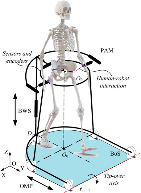
FIGURE 1. Conceptual model of system.
2.1 Hardware description
In this paper, we present a walking assist system facilitating pelvic movements for several reasons. First, based on the walking characteristics of the patients and the problem definition, pelvic movement abnormalities lead to an increase in the double support phase and abnormal gait. Second, pelvic obliquity and pelvic rotation are the key parameters for lower extremity motor function. And third, the pelvic motions are associated with the gait. Therefore, we proposed the PAM to smooth the pelvic motions and install the force/torque sensors, as shown in Figure 2, so we can detect the middle-lateral and vertical displacement of the pelvis, as well as pelvic obliquity and pelvic rotation. Based on the range of pelvic motions during normal gait, the user can achieve normal gait with the help of the PAM. The T5 corresponds to the middle-lateral displacement, which consists of a set of ball splines and two springs, and the displacement is monitored by the force sensors at the end of the spring. Similarly, T6 and T7 are coupled and correspond to the forward-back displacement and pelvic rotation, as the pelvis is connected to the walker by the sliders of the two ball splines. The pose information of the pelvis is given through calculating sensor data. Then there is a revolute pair to achieve pelvic obliquity and tilt, labeled as R8 and R9 respectively. Furthermore, one torque sensor is installed on the joint pontes between the BWS and the PAM to detect the vertical motion.
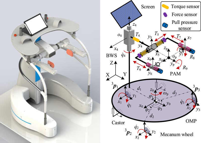
FIGURE 2. The CAD model of the walker and coordinate system.
For weight offloading and reduction of the cardiopulmonary burden, a servo motor is designed to realize the approximately 0.5 m vertical displacement of the pelvis and provide subjects with appropriate body weight support via a guide screw and a set of linear guideways. The error between the offloading value and sensor signal is used to trace the pelvic motion, and the system control is implemented in TwinCAT2 using a controller (Beckhoff PLC CX5130). On the top of the BWS, the control platform is installed to support the upper body weight and implement the interaction control. Two joysticks and one depth-sensing camera (Surface Go 2) were used to monitor the human-machine information, the user manipulated the walker via the left or right joystick according to the actual condition. The depth-sensing camera is used to obtain the facial features, as the heading angle can reveal the motion intention.
The primary aim of the OMP is to provide over-ground mobility, and thus achieve gait assistance. The OMP consists of three active wheels to provide power, two passive castors to maintain balance, and a U-shaped rigid steel frame to provide an installation base. According to the motions of lower limbs, a U-shaped rigid steel frame is designed to satisfy approximately 0.5 m of free space in the medio/lateral direction, and 0.8 m of free space in the anterior/posterior direction. For the active omnidirectional wheels, the walker is capable of rotation with arbitrary radius.
As described above, the multimodal Human-Robot Interaction (mHRI) is used to estimate the motion intention: the video image from the real sense camera, which belongs to the cHRI. the interaction forces from the load sensors and the motion vector from the joysticks were employed to detect the interaction information, which belongs to the pHRI.
2.2 Problem statement
In the interactive control process of lower limb rehabilitation robot, it is easy to produce more interference signals for the abnormal walking characteristics of the hemiplegic patients, which leads to the indisposed control performance, and then the robotic walkers cannot assist the users to finish the Activity of Daily Living (ADL) tasks. For the problem at hand, mobile rehab robots need to perceive the motion intentions via the cHRI or the pHRI. For passive walkers, the problem is to detect the safety of the user and brake at the right moment. For the active walkers, the HRI is more important for that the system needs to identify the gait pattern accurately and output appropriate velocity to trace the user. According to the above analysis, the two major issues are: 1) estimating the motion intentions; and 2) calculating output velocity.
For estimating the motion intentions, the JARoW-II active robotic walker obtained the coordinate data for the surface of the user’s lower limbs via the two LRFs (Hokuyo Automatic Co. Ltd. model URG-04LX), the advantage of the scheme is capable of the gait information acquisition, but the drawback is large amounts of computation; the KineAssist rehab robot estimated the interaction forces via two ATI force/torque sensors at both side of the pelvis, the advantage of the scheme is capable of the pelvic information acquisition, but the drawback is exorbitant price (Hurt et al., 2015). To sum up, there exist some problems with the current solution, such as high cost, poor intelligence, and inaccurate intention recognition.
For calculating output velocity, the mobile robots following behind a user is a common approach in walker-assisted locomotion (Seo and Lee, 2009), and it is more natural and comfortable for the person to control the walker if the robot is placed in front of the user (Haoyong et al., 2003). But the control problem is the position error between the mobile robots and humans, for the signal delay from the cHRI or the pHRI. The potential solution is to control the system to minimize the tracking error between humans and the mobile robot locomotion. A virtual spring model is used to absorb the gap between the human and the mobile robot motion via the input velocity generated on the basis of an elastic force (Morioka et al., 2004). But for pHRI, this solution can lead to a radical change in the interaction force.
Therefore, we present a method to obtain the heading angle E, the pelvic pose F, and the motion vector H via the camera, the force sensors, and the joysticks respectively, as shown in Figure 3, and go through several steps to get the classification of gait pattern, then output the velocity to minimize the tracking error, the methods are detailed in the next chapter.
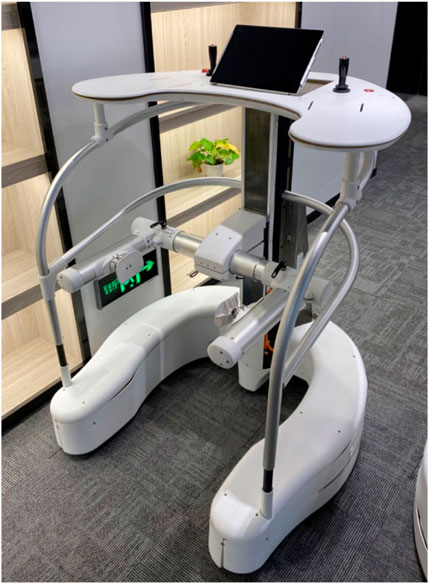
FIGURE 3. The physical prototype of the robotic walker.
3 Modeling and control
In order to improve the movement performance and the controllability of the robotic walker, the robot movement control model was produced in this chapter based on the robot kinematics, the active and passive joints were involved. The relation between the tacking velocity and the output of the servo motors was derived. On this basis, the control method was presented, which is two stages of control: the first step performed the mHRI detection via the camera, the force sensors, and the joysticks; while the second step corresponded to an inverse kinematic controller.
3.1 Kinematic model
The human-robot interaction model is shown in Figure 2, The variables and parameters used in this paper are defined as follows: the
Defining the velocity matrix of the OMP relative to the global coordinate system as
According to robot kinematics and the earlier paper (Ji et al., 2021), deducing the mapping relation
where
Then, the velocity vector
where
According to the derivation of the earlier paper, for the active joints, the inverse Jacobian matrix can be obtained as Eq. 6,
Through the matrix inverse in the MATLAB, the explicit expression of the Jacobian matrix can be written as Eq. 7:
For the passive part of the robotic walker, as shown in Figure 4, the pelvic motions can lead to a change of position, so the D-H method is used to calculate the relation between the current pelvic pose and the passive joints, then we can obtain the current pelvic pose through the inverse kinematics and sensor data.
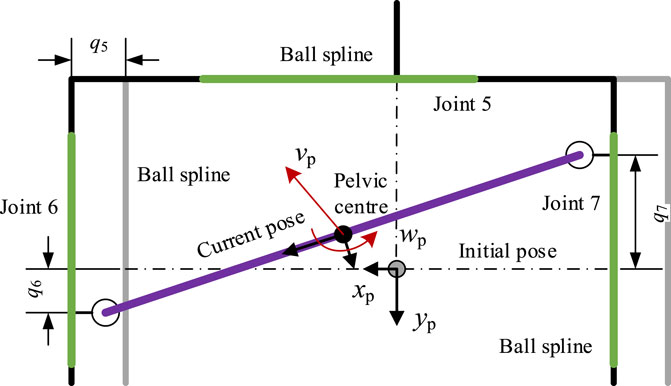
FIGURE 4. Mechanical construction of the PAM.
For the passive joint i, the rotation matrix
According to Eq. 1, the position vector and rotation matrix of the joint can be obtained as Eqs 10, 11:
Via Eq. 4, a velocity vector in the local coordinate system can be obtained. To translate into the velocity vector in the global coordinate system, taking point
where
3.2 Intention prediction
The multimodal human-robot interaction model is shown in Figure 5, the facial recognition is the cHRI, which is used to detect the Yaw, Roll, and Pitch angle of the head via a real sense camera, then we can predict the direction the user wants to go and extract the angle feature
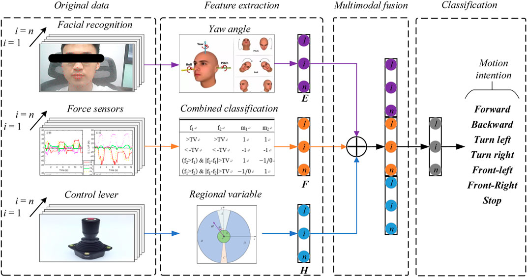
FIGURE 5. The multimodal human-robot interaction model of the robotic walker.
For the control levers, we can control the walker with two levers as described in the previous paper (Ji et al., 2021). This paper addressed the prediction pattern with a single control lever, defining the lever vector as
1) Classify the workspace of the lever into five regions OABCD, defined as Eqs 12a–16:
where
2) signal collection of the lever vector, as shown in Figure 6, obtain the direction and magnitude of the vector, save the data in time order;
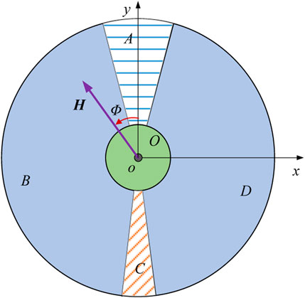
FIGURE 6. Definition of the five regions OABCD.
3) predict the motion intention via the current region and change of the region, the relation between the change rule and the motion intention is shown in Table 1.
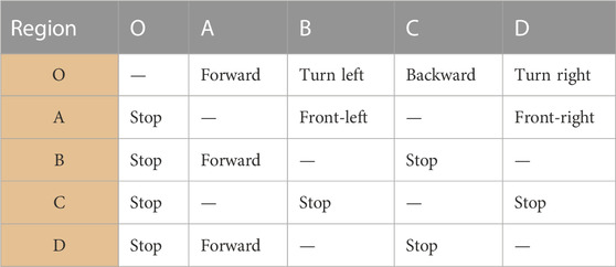
TABLE 1. Basic movement pattern of the robotic walker.
The basic movement pattern of the robotic walker is shown in Table 1, forward, backward, turn left, turn right, front-left, front-right, and stop respectively. When the change rule is of the O-A, B-A, or D-A, the system predicts the human intends to move forward; when the change rule is of the O-C, the system predicts the human intends to move backward; when the change rule is of the O-B, the system predicts the human intends to turn left; when the change rule is of the O-D, the system predicts the human intends to turn right; when the change rule is of the A-B, the system predicts the human intends to move to front-left; when the change rule is of the A-D, the system predicts the human intend to move to front-right; and the walker will stop with other conditions. Besides, when the interaction forces show abnormal values or rapid change, or the real sense camera detects a dangerous expression, or the emergency stop button is pressed, the walker performs the Stop action.
The decision rule by the interaction forces has been discussed in the previous paper (Ji et al., 2020). For facial recognition, we use a real sense camera to detect the Yaw, Roll, and Pitch angle of the head, the angle feature
Then the controller calculates the output based on the classification results and interaction single, the function relationship can be expressed as Eq. 17:
After the signal has been processed, we define the dead zone to improve stability, then the robot velocity in the local coordinate system can be expressed as Eqs 18, 19:
where
Then by Eq. 12 to calculate the robot velocity in the global coordinate system
4 Experiment and verification
To prove the effectiveness of the proposed control method, a preliminary experiment with three healthy volunteers was carried out in this study. In the preliminary experiment, three healthy volunteers were asked to finish a task within the required time. Three kinds of trajectories were chosen to simulate the ADL task which were printed on the ground, and then the actual path data was recorded by the Programmable Logic Controller (PLC).
4.1 Experimental setup
The robotic walker was tested with the proposed control method and three health volunteers. The “∞” path, “○” path, and “□” path were used to test if the robotic walker could allow the volunteers to walk naturally. The experiment was carried out to evaluate the control performance by asking the three healthy volunteers to walk along the three given paths respectively. Three healthy adults were selected for the experiment study, and three men with an average age of 30.7, height of 173.3 cm, and weight of 71.7 kg were involved. Before the experiment, the volunteer wore a harness to connect with the robotic walker and adjusted the pelvic width. Inclusion criteria are no abnormalities in the nervous system, muscle-bone system, or found during physical examination, and having had no special balance training previously. A commonly used “∞” curve was firstly painted in black on the ground as the target path that the volunteers were asked to follow, and then the “∞” curve was replaced with a “○” and “□” curve, respectively. Each person had one chance to try the three paths and the experiment results were recorded by the encoders of the three omni wheels. In the experiment, the volunteers were asked to familiarize the operation of the robotic walker for 5 min and then finish the task within 60 s.
4.2 Data processing
For the tracking error analysis, the three target paths were mathematized in MATLAB to ensure the consistency between the painted curve and the mathematized curve. The actual position and orientation of the robotic walker were calculated by the three encoders of the driving wheel, which were calculated by the previously derived formulas. Then calculating the error between the actual path and reference pose samples, for comparison, the amount of the discrete point was processed into consistent. The normalized integral square error (ISE) cost function was used to evaluate the path-tracking error.
Descriptive and analytical statistics were performed by the SPSS 22.0 and MATLAB 2016b. The actual paths were time normalized to 100% reference path. The error mean and standard deviation of position and orientation is defined by the difference between the target path and the reference path. The experimental results are shown in Figures 7–9.
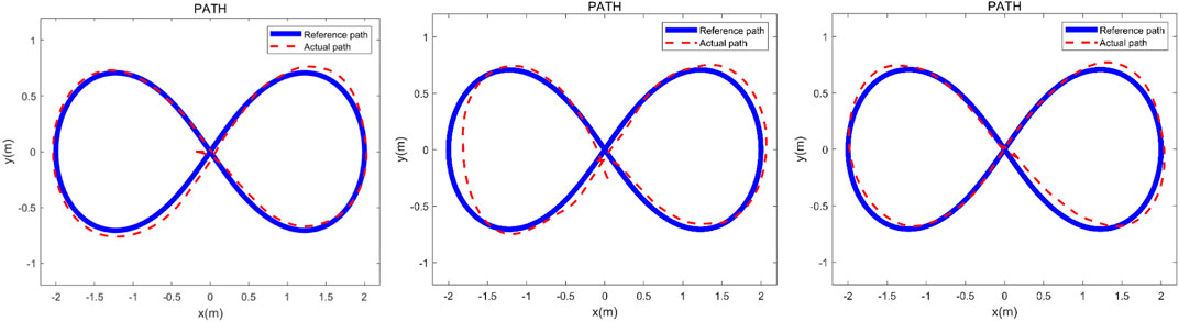
FIGURE 7. Verification experiment to finish the “∞” curve with three healthy adults. The heavy line is the reference path and the dashed line represents the actual path.

FIGURE 8. Verification experiment to finish the “○” curve with three healthy adults. The heavy line is the reference path and the dashed line represents the actual path.
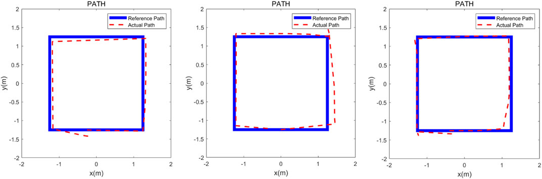
FIGURE 9. Verification experiment to finish the “□” curve with three healthy adults. The heavy line is the reference path and the dashed line represents the actual path.
5 Discussion
The three experimental results are shown in Figures 7–9, the volunteers finished the task within the prescribed time, it can be seen that the volunteers can follow the three given paths within an acceptable error range, and the “∞” curve is the most difficult task, indicating that the robotic walker allows the person to walk naturally under the mHRI and control with very minimal effort. As shown in Figure 7, the initial point and the endpoint are in the center of the curve, and volunteer 1 and volunteer 2 showed relatively big errors, and the ISE results are 2.69, 3.84, and 3.43 respectively, compared with the previous experimental results, the proposed method has a significant improvement. For the verification experiment to finish the “○” curve, the volunteers easily finished the task within the prescribed time, and the ISE results are 2.85, 2.15, and 3.76 respectively. For the “□” curve experiment, the volunteers easily finished the task within the prescribed time, and the ISE results are 2.44, 2.96, and 1.98 respectively. The results show that subjects can operate the walker to follow the prescribed curve, and it is evident that the walker can recognize the motion intent accurately and the volunteers can control the walker to fulfill the given task. This tracking experiment paves the way for the clinical application.
6 Conclusion
The present work demonstrates that the robotic walker is capable of intent recognition with the proposed mHRI system, in the ADL assistance, the robotic walker has the potential to reduce the stress on relatives of the patient. The proposed control algorithm for the motion control is derived via the robot kinematics and multimodal fusion human-robot interaction and proved to be effective in the pursuit movement by the preliminary experiment with three health volunteers. The experiment result shows that the robotic walker can effectively predict the user’s movement intention and provide appropriate output velocity to track. The RRW system may be used to improve the gait function of stroke survivors which is crucial to their quality of life.
Data availability statement
The original contributions presented in the study are included in the article/supplementary material, further inquiries can be directed to the corresponding authors.
Author contributions
TG: Funding acquisition, Resources, Writing–review and editing. DC: Investigation, Writing–review and editing. GW: Supervision, Writing–review and editing. WZ: Data curation, Writing–original draft. JZ: Formal Analysis, Writing–original draft. ZO: Validation, Writing–review and editing. FZ: Resources, Writing–review and editing. RS: Writing–original draft, Software. JJ: Conceptualization, Writing–original draft. WC: Funding acquisition, Project administration, Writing–review and editing.
Funding
The author(s) declare that no financial support was received for the research, authorship, and/or publication of this article.
Conflict of interest
Authors GW, WZ, JZ, ZQ, FZ, and RS were employed by AVIC Changhe Aircraft Industry (Group) Corporation Ltd.
The remaining authors declare that the research was conducted in the absence of any commercial or financial relationships that could be construed as a potential conflict of interest.
Publisher’s note
All claims expressed in this article are solely those of the authors and do not necessarily represent those of their affiliated organizations, or those of the publisher, the editors and the reviewers. Any product that may be evaluated in this article, or claim that may be made by its manufacturer, is not guaranteed or endorsed by the publisher.
References
Calabrò, R. S., Sorrentino, G., Cassio, A., Mazzoli, D., Andrenelli, E., Bizzarini, E., et al. (2021). Robotic-assisted gait rehabilitation following stroke: a systematic review of current guidelines and practical clinical recommendations. Eur. J. Phys. Rehabil. Med. 57 (3), 460–471. doi:10.23736/s1973-9087.21.06887-8
Capecci, M., Pournajaf, S., Galafate, D., Sale, P., Le Pera, D., Goffredo, M., et al. (2019). Clinical effects of robot-assisted gait training and treadmill training for Parkinson's disease. A randomized controlled trial. Ann. Phys. Rehabil. Med. 62 (5), 303–312. doi:10.1016/j.rehab.2019.06.016
Chen, Y., Chen, Y., Zheng, K., Dodakian, L., See, J., Zhou, R., et al. (2020). A qualitative study on user acceptance of a home-based stroke telerehabilitation system. Top. Stroke Rehabil. 27 (2), 81–92. doi:10.1080/10749357.2019.1683792
Cifuentes, C. A., and Anselmo, F. (2016). Human-robot interaction strategies for walker-assisted locomotion.
Feigin, V. L., Brainin, M., Norrving, B., Martins, S., Sacco, R. L., Hacke, W., et al. (2022). World stroke organization (WSO): global stroke fact sheet 2022. Int. J. Stroke 17 (1), 18–29. doi:10.1177/17474930211065917
Frizera, A., Ceres, R., Frizera-Neto, A., Ceres, R., Rocon, E., and Pons, J. L. (2011). Empowering and assisting natural human mobility: the simbiosis walker. Int. J. Adv. Robot. Syst. 80 (3), 29–50. doi:10.5772/10666
GBD Stark, B. A., Johnson, C. O., Roth, G. A., Bisignano, C., Abady, G. G., et al. (2021). Global, regional, and national burden of stroke and its risk factors, 1990–2019: a systematic analysis for the Global Burden of Disease Study 2019. Lancet Neurol. 20 (10), 795–820. doi:10.1016/s1474-4422(21)00252-0
Haoyong, Yu., Spenko, M., and Dubowsky, S. (2003). An adaptive shared control system for an intelligent mobility aid for the elderly. Auton. Robots 15 (1), 53–66. doi:10.1023/a:1024488717009
Horii, T., and Nagai, Y. (2021). Active inference through energy minimization in multimodal affective human-robot interaction. Front. Robot. AI 8, 684401. doi:10.3389/frobt.2021.684401
Hurt, C. P., Burgess, J. K., and Brown, D. A. (2015). Limb contribution to increased self-selected walking speeds during body weight support in individuals poststroke. Gait Posture 41 (3), 857–859. doi:10.1016/j.gaitpost.2015.02.004
Jarva, E., Mikkonen, K., Tuomikoski, A. M., Kääriäinen, M., Meriläinen, M., Karsikas, E., et al. (2021). Healthcare professionals' competence in stroke care pathways: a mixed-methods systematic review. J. Clin. Nurs. 30 (9-10), 1206–1235. doi:10.1111/jocn.15612
Ji, J., Chen, W., Wang, W., and Xi, J. (2021). Design and control of an omni-directional robotic walker based on human–machine interaction. IEEE Access 9, 111358–111367. doi:10.1109/ACCESS.2021.3103202
Ji, J., Guo, S., Xi, F., and Zhang, L. (2020). Design and analysis of a smart rehabilitation walker with passive pelvic mechanism. J. Mech. Robotics 12 (3). doi:10.1115/1.4045509
Lesaine, E., Francis-Oliviero, F., Domecq, S., Bijon, M., Cetran, L., Coste, P., et al. (2022). Effects of healthcare system transformations spurred by the COVID-19 pandemic on management of stroke and STEMI: a registry-based cohort study in France. BMJ Open 12 (9), e061025. doi:10.1136/bmjopen-2022-061025
Mirelman, A., Bonato, P., Camicioli, R., Ellis, T. D., Giladi, N., Hamilton, J. L., et al. (2019). Gait impairments in Parkinson's disease. Lancet Neurol. 18 (7), 697–708. doi:10.1016/s1474-4422(19)30044-4
Mojadidi, M. K., Mahmoud, A. N., and Elgendy, I. Y. (2017). Percutaneous patent foramen ovale closure for cryptogenic stroke: learning from clinical trial and error. J. Thorac. Dis. 9 (11), 4222–4225. doi:10.21037/jtd.2017.09.153
Moreira, R., Alves, J., Matias, A., and Santos, C. (2019). Smart and assistive walker - ASBGo: rehabilitation robotics: a smart-walker to assist ataxic patients. Adv. Exp. Med. Biol. 1170, 37–68. doi:10.1007/978-3-030-24230-5_2
Morioka, K., Lee, J. H., and Hashimoto, H. (2004). Human-following mobile robot in a distributed intelligent sensor network. IEEE Trans. Ind. Electron. 51 (1), 229–237. doi:10.1109/tie.2003.821894
Nam, K. Y., Kim, H. J., Kwon, B. S., Park, J. W., Lee, H. J., and Yoo, A. (2017). Robot-assisted gait training (Lokomat) improves walking function and activity in people with spinal cord injury: a systematic review. J. Neuroeng Rehabil. 14 (1), 24. doi:10.1186/s12984-017-0232-3
Ohnuma, T., Lee, G., and Chong, N. Y. (2017). Development of JARoW-II active robotic walker reflecting pelvic movements while walking. Intell. Serv. Robot. 10, 95–107. doi:10.1007/s11370-016-0212-7
Pons, J., Ceres, R., and Calderón, L. (2008). “Chapter introduction to wearable robots and exoskeletons,” in Wearable robots: biomechatronic exoskeletons (Wiley), 1–5.
Reisman, D. S., Bastian, A. J., and Morton, S. M. (2010). Neurophysiologic and rehabilitation insights from the split-belt and other locomotor adaptation paradigms. Phys. Ther. 90 (2), 187–195. doi:10.2522/ptj.20090073
Seo, K. H., and Lee, J. J. (2009). The development of two mobile gait rehabilitation systems. IEEE Trans. Neural Syst. Rehabil. Eng. 17 (2), 156–166. doi:10.1109/tnsre.2009.2015179
Sharma, R., Pavlovic, V. I., and Huang, T. S. (1998). Toward multimodal human-computer interface, in Proc. IEEE, 860(5): 853–869. doi:10.1109/5.664275
Sierra, M., Sergio, D., Garzón, M., and Cifuentes, C. A. (2019). Human–robot–environment interaction interface for smart walker assisted gait: AGoRA walker. Sensors 19 (13), 2897. doi:10.3390/s19132897
Sierra M., S. D., Jimenez, M. F., Múnera, M. C., Bastos, T., Frizera-Neto, A., and Cifuentes, C. A. (2019). A therapist helping hand for walker-assisted gait rehabilitation: a pre-clinical assessment," 2019 ieee 4th Colombian conference on automatic control. Medellin, Colombia: CCAC, 1–6.
Su, H., Qi, W., Chen, J., Yang, C., Sandoval, J., and Laribi, M. A. (2023). Recent advancements in multimodal human-robot interaction. Front. Neurorobot 17, 1084000. doi:10.3389/fnbot.2023.1084000
Valadão, C., Caldeira, E., Bastos-Filho, T., Frizera-Neto, A., and Carelli, R. (2016). A new controller for a smart walker based on human-robot formation. Sensors 16, 1116. doi:10.3390/s16071116
Wang, W., Gong, T., Song, Z., Wang, Z., and Ji, J. (2023). Simulation study on assist-as-needed control of a rehabilitation robotic walker. Technol. Health Care 31 (S1), 293–302. doi:10.3233/thc-236025
Keywords: kinematic modeling, robotic walker, multimodal fusion, human-robot interaction control, stroke
Citation: Gong T, Chen D, Wang G, Zhang W, Zhang J, Ouyang Z, Zhang F, Sun R, Ji JC and Chen W (2024) Multimodal fusion and human-robot interaction control of an intelligent robot. Front. Bioeng. Biotechnol. 11:1310247. doi: 10.3389/fbioe.2023.1310247
Received: 09 October 2023; Accepted: 13 December 2023;
Published: 04 January 2024.
Edited by:
Wujing Cao, Chinese Academy of Sciences (CAS), ChinaReviewed by:
Chengjie Zhang, Shanghai Jiao Tong University, ChinaLiu Ying, East China Jiaotong University, China
Copyright © 2024 Gong, Chen, Wang, Zhang, Zhang, Ouyang, Zhang, Sun, Ji and Chen. This is an open-access article distributed under the terms of the Creative Commons Attribution License (CC BY). The use, distribution or reproduction in other forums is permitted, provided the original author(s) and the copyright owner(s) are credited and that the original publication in this journal is cited, in accordance with accepted academic practice. No use, distribution or reproduction is permitted which does not comply with these terms.
*Correspondence: Jiancheng Charles Ji, amNqaTIwQHN6cHQuZWR1LmNu
†These authors share first authorship
‡These authors share last authorship