 Davide Colombi*
 Bo Xu
Bo Xu David Anguiano SanjurjoParamananda Joshi
 Fatemeh Ghasemifard
 Carla Di PaolaChrister Törnevik
- Ericsson Research, Ericsson AB, Stockholm, Sweden
In March 2020, the International Commission on Non-Ionizing Radiation Protection (ICNIRP) released its new guidelines (ICNIRP 2020) on the limitation of radio frequency (RF) electromagnetic fields (EMF) exposure in the frequency range 100 kHz–300 GHz. These have taken several years to develop and include the review of the latest scientific literature. Most countries worldwide currently apply the RF-EMF exposure limits provided in the ICNIRP 1998 guidelines and are expected to align their regulations according to the recently revised limits. In this paper, the implications of the ICNIRP 2020 guidelines on the RF-EMF compliance of base stations (BSs) for mobile communications are analyzed in detail. The study covers different types of BS products, from low-power small cells to macro cell equipment, operating within different frequency bands and of relevance for 2G to 5G mobile technologies. A direct comparison of the BS RF-EMF exclusion zones (or compliance boundaries), when the ICNIRP 2020 and the ICNIRP 1998 limits are applied, is provided. Since existing and future mobile equipment infrastructure is likely to be required to comply with the ICNIRP 2020 guidelines, the paper provides useful information to mobile equipment manufacturers, mobile operators, standardization bodies and regulators.
Introduction
On March 11, 2020, ICNIRP released new guidelines, referred in this report as “ICNIRP 2020,” for exposure to RF EMF in the frequency range 100 kHz–300 GHz (ICNIRP, 2020a). As a consequence, many countries worldwide are expected to update their radio wave standards based on the new ICNIRP international guidelines (e.g., ARPANSA, 2021). Several national regulations are likely to change from the previous version of the ICNIRP guidelines (ICNIRP, 1998), referred in this report as “ICNIRP, 1998,” to the new ones. While the ICNIRP (2020a) limits have been confirmed to be protective for current technologies (including 5G), some changes have been introduced making the guidelines “future-proofed” (ICNIRP, 2020b). A summary of the main differences between ICNIRP 2020 and the previous guidelines is provided by ICNIRP (ICNIRP, 2020c).
Mobile equipment, including BSs and mobile devices, need to comply with RF EMF exposure limits, such as those recommended by ICNIRP. These exposure limits are set far below the lowest level required to cause adverse health effects which are related to induced heating in the body. The guidelines are technology independent and apply equally to all existing mobile technologies (from 2G to 5G) within the specified frequency range. Several studies have analyzed the implications that the international exposure guidelines have on the design, operation, and deployment of mobile equipment. For instance (Colombi et al., 2015), derived an estimate of the maximum transmit power based on the numerical model of canonical antennas operating in close proximity of the body (Thors et al, 2016). Conducted a systematic investigation of the allowed output power and maximum equivalent isotropic radiated power (EIRP) of array antennas operating at frequencies above 10 GHz. These studies were conducted before the publication of the revised limits, and only a single publication addressed the performance of portable devices (e.g., mobile phones) when complying with ICNIRP 2020 (He et al, 2020). To date, and to the knowledge of the authors, no study evaluating the implications of EMF compliance with ICNIRP 2020 for BSs exists.
EMF compliance for BSs typically involves establishing the so-called compliance boundaries or exclusion zones, i.e., the volume surrounding the base station antenna (or the base station itself when radio transmitters and antenna are tightly integrated) outside of which EMF exposure is below the limits. Therefore, in this work, the implications of ICNIRP 2020 are addressed by establishing the compliance boundaries for several BSs, representative of different technologies, installation scenarios, and frequency bands. Results are provided for conventional multi-column passive antennas as well as massive MIMO (mMIMO) antennas, which are becoming more common with the deployment of 5G. Low-power BSs typically used for indoor coverage are also addressed. Considerations are made for different frequencies, within relevant mobile communication bands below as well as above 6 GHz.
A brief summary of the ICNIRP 2020 limits is given in Section 2. The methodology used to assess the BS compliance boundaries for different types of antennas and BS products is provided in Section 3. Results are presented in Section 4 while the implications of the ICNIRP 2020 limits for brief exposure are specifically addressed in Section 5. Some reflections about the results are given in Section 6. Final conclusions are drawn in Section 7.
Summary of the RF-EMF Limits Specified by ICNIRP 2020
ICNIRP RF EMF exposure limits are given in terms of basic restrictions, which relate to physical quantities inside the body, and in terms of reference levels, which are external field quantities derived from the basic restrictions. The reference levels provide a more practical mean of assessing compliance in most situations. Basic restrictions and reference levels are specified for whole-body and local exposure. A summary of the basic restrictions applicable for the general public and for frequencies above 400 MHz, as given by ICNIRP 2020, is provided in Annex A, Supplementary Table A1 (as supplementary material). The corresponding reference levels are presented in Supplementary Table A2.
ICNIRP 2020 also provides basic restrictions and reference levels applicable for “brief exposure,” i.e., for “exposure from any pulse, group of pulses, or subgroup of pulses in a train, as well as from the summation of exposures (including non-pulsed EMFs), delivered in t seconds (t < 360 s)”. Such limits are only applicable for local exposure (Supplementary Table A3). For convenience, a brief summary of the limits is included in Annex A (as supplementary material) but the tables provided in the guidelines (ICNIRP, 2020a), should be used as a more exhaustive and rigorous reference.
In Section 3, the compliance boundaries (exclusion zones) for several BSs are determined according to ICNIRP 2020 and compared to those obtained when using ICNIRP 1998, for which the applicable limits are summarized in Supplementary Tables A4, A5.
EMF compliance for BSs is typically assessed by means of the reference levels since the usage of the basic restrictions is often unpractical (IEC, 2017). The main differences in the reference levels specified by ICNIRP 2020 compared with ICNIRP 1998 are listed below and summarized in Table 1 (only frequencies above 400 MHz are considered):
• Below 10 GHz, ICNIRP 2020 incident power density and field strength limit values applicable for whole-body exposure (i.e., spatially averaged over an area corresponding to the body surface) are the same as those provided by ICNIRP 1998. ICNIRP 1998 does not provide specific reference levels for local exposure but the whole-body reference levels can be applied as spatial-peak values, when it is necessary to assess compliance for partial-body exposure. ICNIRP 2020 introduces additional reference levels for local exposure that are higher than those applicable for whole-body (e.g., of a factor of 4 between 2 and 6 GHz). It follows that the reference levels for local exposure in ICNIRP 2020 are larger than those used according to ICNIRP 1998.
• Above 10 GHz, ICNIRP 1998 specifies the limit in terms of incident power density averaged over 20 cm2. The same power density limit values are provided by ICNIRP 2020 for whole-body exposure reference levels and are intended to be averaged over an area corresponding to the whole-body surface (much larger than 20 cm2). At the same time, reference levels for local exposure are introduced and are to be averaged over a smaller area such as 4 cm2 (above 30 GHz, averaging areas of both 4 and 1 cm2 apply; for the latter, the corresponding power density limit values have to be doubled.) The local incident power density limits are higher than the whole-body ones also in this frequency range (e.g., about a factor of 3 at 30 GHz).
• The averaging time applicable for whole-body exposure according to ICNIRP 2020 is extended to 30 min in the entire frequency range. The corresponding time for local exposure is 6 min. ICNIRP 1998 averaging time is dependent on frequency.
• In the reactive near-field region and at frequencies above 2 GHz, the reference levels cannot be used, and compliance with ICNIRP 2020 guidelines needs to be assessed by means of the basic restrictions.
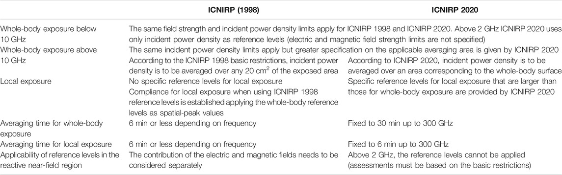
TABLE 1. Comparison of the reference levels applicable to the general public as specified by ICNIRP 2020 and ICNRP 1998 at frequencies above 400 MHz. Brief exposure limits applicable for intervals below 6 min are discussed separately in Section 5.
Basic restrictions may be used to assess EMF compliance for BS products with very low power, which are addressed separately in Section 4.3. New local energy limits applicable for intervals of less than 6 min have also been specified by ICNIRP 2020 and are discussed in detail in Section 5.
The ICNIRP 2020 guidelines, as before, differentiate between occupationally exposed individuals and general public. The limits for occupational exposure can be derived from those applicable to the general public by scaling them with a factor of 5.
Methods
Compliance Boundary Evaluation
The BS compliance boundary is characterized by a complex shape (iso-surface), which depends on the radiation characteristics of the antenna. More practical compliance boundaries can be used by enclosing the iso-surface with volumes of simpler shape, which are also easier to communicate (IEC, 2017) and therefore to implement when installing a BS. In this paper, a box-shaped compliance boundary is used, characterized by its width, height, and front compliance distance, as depicted in Figure 1. While the fit to the iso-surface compliance boundary is made as tight as possible, the box might overestimate the compliance distance is some directions. Outside of this box, the RF exposure is below the limits.
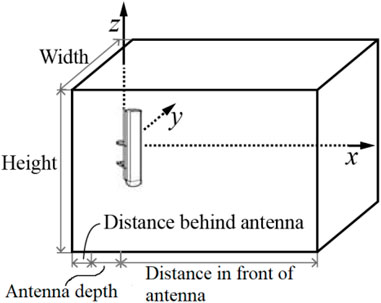
FIGURE 1. Box-shaped structure specifying the compliance boundary surrounding the BS antenna.
Exposure assessment standards, such as (IEC, 2017), define RF exposure assessment methodologies applicable for BSs, including measurements, advanced numerical methods, and basic computation techniques. Such standards also provide criteria to identify the most suitable evaluation method depending on the source characteristics and on the purpose of the assessment (e.g., product compliance, product installation compliance, or in-situ assessments). Calculations using the spherical formula is the most common and standard way to assess the compliance boundary of base station antennas:
where
The antenna gain values used in this paper are provided, on the horizontal and vertical cuts (see Section 3.2), directly by the antenna manufacturers, based on measurements of the radiation pattern. For mMIMO products, characterized by several antenna ports, the traffic beams are steered in different directions, depending on the location of the users requesting service. Therefore,
The iso-surface compliance boundaries for the selected BS antennas are obtained by solving the following equation for
where
A MATLAB-based Ericsson internal software tool was used to calculate power density according to expressions 1) and 2) and to plot the corresponding compliance boundary (3). The tool provides an interface for users to select antenna pattern files and insert the parameters needed to calculate the power density, such as the antenna accepted power.
While for ICNIRP 1998, the compliance boundaries are obtained by means of expression 3) using the reference levels in Supplementary Table A5 as spatial peak values, ICNIRP 2020 provides specific reference levels for both local and whole-body exposure (both to be met). Whole-body incident power density is therefore to be averaged over an area corresponding to the whole-body surface. While ICNIRP does not recommend a specific size of this surface, in this work averaging is performed over a line, corresponding to the height of the child whole-body phantom specified in IEC 62232, i.e., 0.96 m. The average power density,
IEC 62232 (IEC, 2017) provides recommendation on different averaging schemes for whole-body exposure, including vertical lines and cross-sectional areas. Among these, for a fixed body height, averaging over a line provides conservative results with respect to other alternatives. In addition, while it is reasonable to conduct averaging assuming the body height oriented parallel to the antenna axes (i.e., along z), the orientation of the body width, and therefore the orientation of the cross-sectional surface, might be arbitrary and difficult to set (any direction on the xy-plane could be justifiable).
Selected BS Products
The relevant characteristics of the BS products or BS antennas selected for this study are summarized in Table 2. Antennas are chosen to cover a wide range of frequencies and parameters (in terms of dimensions, gain, half power beamwidth, etc.) relevant for mobile technologies, from 2G to 5G. The antenna gain values in the horizontal cut
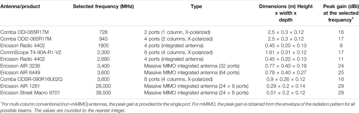
TABLE 2. Characteristics of the selected BS antennas or BS products (for integrated antennas).
For BS operating below 6 GHz, the compliance boundaries are determined for a time-averaged input power of 5, 10, 40, 100, 200, and 250 W. Such power levels are selected to span over a wide range of installation scenarios but might differ from what is configurable in reality by the BS. For instance, the Ericsson Radio 4402 is a micro BS product that can be set to operate at power levels up to 20 W and the actual maximum time-averaged transmitted power levels (Thors et al, 2017) for Ericsson mMIMO products AIR 3236 and AIR 6449 are up to 80 W. Since the objective of this work is to study the implications of the updated EMF limits rather than to determine the EMF compliance distance for specific products, the broad choice of frequencies, antenna types, and power levels allows to draw general conclusions on the impact of the ICNIRP 2020 guidelines on EMF compliance of BSs. The same consideration can be made with regard to the approximation in Eq. 5, which assumes the antenna gain in elevation to be independent of the azimuth angle; although slightly more accurate reconstruction methods of the 3D gain from the radiation pattern on the horizontal and vertical cuts have been proposed, e.g., (Vasiliadis et al., 2005), they are unnecessary for the purpose of this study.
BSs operating at 28 and 38.5 GHz are characterized by power levels that are much lower than what are typically supported for “low-band” and “mid-band” BSs (e.g. for the selected BS products, the maximum configurable power is currently 1 W). The compliance boundaries for the “high-band” BS products are therefore determined for 100 mW, 200 mW, 400 mW, 1 W, 2 W, and 5 W.
Results
Micro and Macro BS Operating Below 6 GHz
An example of an iso-surface compliance boundary obtained according to the procedure described in Section 3 for ICNIRP 2020 limits is plotted in Figure 2 for the Ericsson AIR 3236, determined from the radiation pattern envelope of the and for a power level of 40 W. The enclosing box-shaped compliance boundary is also visible in the same figure from a picture of the vertical cut (the box is always centered around the antenna in the z direction so the height of the box is conservatively chosen to be equal above and below the antenna).
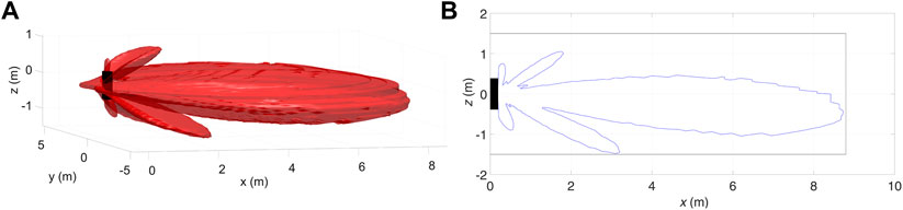
FIGURE 2. (A) an example of the iso-surface compliance boundary (BS Ericsson AIR 3236 assuming 40 W transmitted power). (B) the corresponding vertical cut including the cross-section of the enclosing box-shaped compliance boundary.
The compliance boundary box dimensions (enclosing the iso-surface) for each of the listed BS antennas operating below 6 GHz are provided in Figures 3–5, for the front, width, and height, respectively. The pale-blue bars correspond to the dimensions obtained according to ICNIRP 1998, while the corresponding distances to comply with ICNIRP 2020 (including both whole-body and local exposure) are in orange. Six bars for each BS antenna are plotted corresponding to power levels ranging from 5 to 250 W.
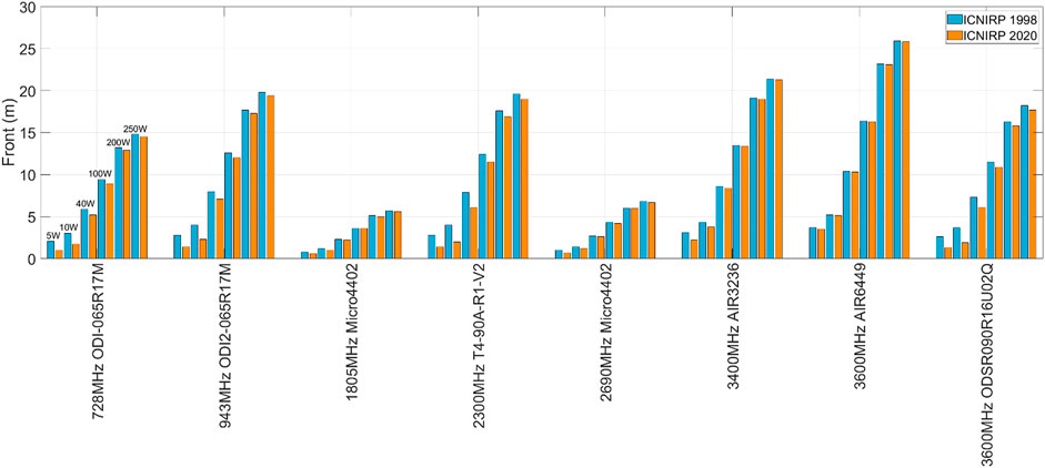
FIGURE 3. Dimensions of the compliance boundary box in the front direction for the selected BS antennas (for frequencies below 6 GHz) obtained by applying ICNIRP 1998 and ICNIRP 2020 general public reference levels for input powers of 5, 10, 40, 100, 200, and 250 W.
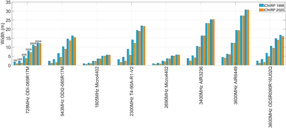
FIGURE 4. Widths of the compliance boundary box for the selected BS antennas (for frequencies below 6 GHz) obtained by applying ICNIRP 1998 and ICNIRP 2020 general public reference levels for input powers of 5, 10, 40, 100, 200, and 250 W.
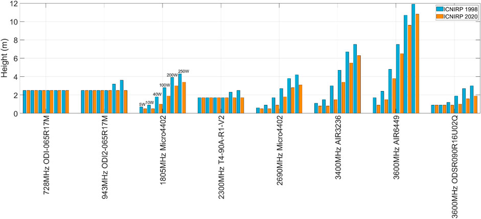
FIGURE 5. Heights of the compliance boundary box for the selected BS antennas (for frequencies below 6 GHz) obtained by applying ICNIRP 1998 and ICNIRP 2020 general public reference levels for input powers of 5, 10, 40, 100, 200, and 250 W.
Figures 3–5 clearly indicate that the compliance boundaries based on ICNIRP 1998 are equal to or larger than those obtained when applying ICNIRP 2020. This result is expected, since the same peak spatial incident power density used to comply with ICNIRP 1998 is intended to be averaged over the whole-body surface according to ICNIRP 2020 (see Supplementary Tables A2, A5). At the same time, the newly introduced local (peak-spatial) reference levels provided by ICNIRP 2020 are higher than the spatial-averaged ones.
Overall, the difference in the compliance boundaries between ICNIRP 1998 and ICNIRP 2020 is small, especially for larger compliance distances, since the incident power density will be relatively uniform over the averaging surface (or line). As peak and spatially averaged power density tend to be equal, this also indicates that, EMF compliance with ICNIRP 2020 for BSs is typically determined by the whole-body reference levels rather than by those for localized exposure.
The compliance boundary box is determined to always enclose the antenna size (or the BS for radio products with integrated antenna(s)). The cases in Figure 5 characterized by “Height” which remains constant with power, correspond to configurations whose exposure is below the limits within the antenna length. Moreover, it must be considered that the pointwise distribution of
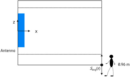
FIGURE 6. Sketch of the compliance boundary height determined when applying ICNIRP 2020 whole-body limits. The black solid line represents the compliance boundary box derived from the
Micro and Macro BS Operating at Frequencies Above 6 GHz
Compliance boundaries are determined for the selected high-frequency BSs according to the method described in Section 3. However, since ICNIRP 2020 extends the validity of the whole-body SAR limit from 10 GHz up to 300 GHz, the whole-body SAR exclusion criteria (IEC, 2017) are applicable also in the millimeter wave frequencies. Assuming an averaging mass of 12.5 kg or more (IEC, 2017), transmitters characterized by total output power below 1 W are inherently compliant with the whole-body SAR limit for the general public (0.08 W/kg). Under this condition, the compliance boundary is determined only based on local reference levels. The local exposure limits above 6 GHz are intended to be spatially averaged over a small area according to ICNIRP 2020 (e.g., 4 cm2). At the compliance boundary, the power density distribution is almost uniform over such a small area and the point spatial power density, in lieu of the spatially averaged value, is deemed to be accurate (the same consideration does not apply to portable devices, for which exposure is assessed in very close proximity of the antenna). A similar observation is made for ICNIRP 1998 for which incident power density above 10 GHz is intended to be averaged over 20 cm2.
The front compliance distances are shown in Figure 7. The compliance distance determined according to ICNIRP 2020 is equal to or shorter than what obtained to comply with ICNIRP 1998. In fact, for power levels below 1 W, the local reference levels of Supplementary Table A2 are larger than the power density limits specified in the previous guidelines by a factor of about 3.5 and 2.9 at 28 and 38.5 GHz, respectively. For power levels above 1 W, for which the whole-body exclusion criteria does not apply, the difference in the compliance distance (between ICNIRP 2020 and ICNIRP 1998) becomes negligible. It is concluded that within the millimeter wave bands, and for mMIMO BSs, ICNIRP 2020 whole-body reference levels become the limiting quantity for EMF compliance already above 1 W. Indeed, ICNIRP 1998 and ICNIRP 2020 whole-body reference level values are the same (although the former are intended to be averaged over 20 cm2 rather than being spatially averaged over the whole-body). The small differences between the pale-blue and orange bars above 1 W in Figure 7 show that the power density is uniformly distributed over the whole-body averaging line.
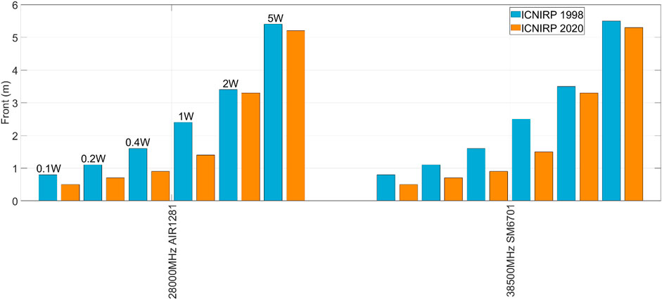
FIGURE 7. Dimension of the compliance boundary box in the front for the selected BS products (for frequencies above 6 GHz) obtained applying ICNIRP 1998 and ICNIRP 2020 general public reference levels for input power of 0.1, 0.2, 0.4, 1, 2 and 5 W.
Low Power BS
For low-power base stations (e.g. below 5 W) operating below 6 GHz, the EMF compliance distance is generally assessed by means of the basic restrictions; a detailed example of a compliance assessment of a local area BS product based on SAR is given in (IEC, 2019). Typically, only local exposure is evaluated, while compliance with whole-body SAR limits is inherently met by means of exclusion criteria1 (IEC, 2017). Since the 6-min average local basic restrictions, specified by ICNIRP 2020 for frequencies below 6 GHz are the same as those provided in ICNIRP 1998, there will be no difference in the compliance boundaries for low-power base station operating in these bands.
Above 6 GHz, within the millimeter wave bands, mMIMO BSs currently operate at power levels well below 5 W but the maximum EIRP is comparable to that of macro or micro products due to the use of antenna arrays characterized by a large aperture. Implications of ICNIRP 2020 on mMIMO products are already addressed in Section 4.2. However, millimeter wave BSs characterized by a smaller number of antenna elements (i.e. lower antenna gain) are also expected. From an EMF compliance standpoint, such products present similar characteristics (in terms of transmit power and antenna design) to user equipment like customer premises equipment, for which the implications of ICNIRP 2020 local exposure limits are addressed in detail by (He et al, 2020). For extremely low power levels (about 15 dBm and below), compliance with ICNIRP 2020 and ICNIRP 1998 is obtained very close to the transmitting antennas (within a few centimeters or even at touch position). At such distances, the field is unevenly spread over the (small) spatial-averaging surface prescribed by the guidelines (4 cm2 for ICNIRP 2020 and 20 cm2 for ICNIRP 1998) and the spatial-average incident power density is expected to be smaller than the spatial peak. The resulting compliance distance (He et al, 2020) is therefore dependent on the antenna design (and not simply on the EIRP) and might decrease with increasing the number of antenna elements (as a result of the near-field power density being spread over a larger area). An example is shown in Figure 8 based on power density data available from (Thors et al, 2017) for 2 × 2 and 4 × 4 antenna arrays at 40 GHz. For power levels above about 15 dBm, ICNIRP 2020 results in shorter compliance distances than ICNIRP 1998.
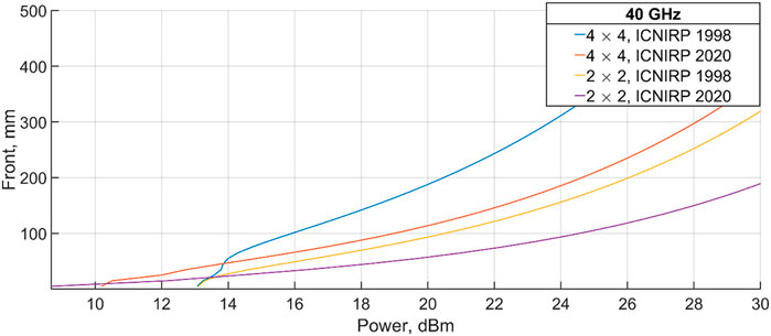
FIGURE 8. Front compliance distance (≥5 mm) for 2 × 2 and 4 × 4 antenna arrays at 40 GHz as function of the power when applying ICNIRP 1998 and ICNIRP 2020 incident power density limit values.
Time Averaging and Brief Exposure Limits
The implications of ICNIRP 2020 brief exposure limits for BSs is addressed by IEC Technical Committee 106 and a detailed analysis is included in the committee draft for voting of IEC 62232 Ed. 3 (IEC, 2021). A similar study is presented in this paper and it is supported with additional results.
By dividing the energy limits on brief exposure of Supplementary Table A3 by the corresponding time interval t, the energy limits can be expressed in terms of time-averaged power over any interval t < 6 min and can be directly compared with the steady state (energy rate) limit values of Supplementary Tables A1, A2. The curve in Figure 9 is normalized to the value obtained for t approaching 6 min (t→360 s). The relative function obtained is the same at any frequency for which the brief exposure limits apply and follows the same trend for both basic restrictions and reference levels. It should be noticed that the local exposure limits (both reference levels and basic restrictions), time-averaged over 6 min, and the brief exposure limits when t→360 s are equivalent. The absolute values for the brief exposure limits can, therefore, be obtained by scaling the curve in Figure 9 with the limits presented in Supplementary Tables A1, A2 for “steady-state” local exposure.
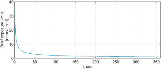
FIGURE 9. Limit for “brief exposure” (t < 6 min), see Supplementary Table A3, divided by the corresponding time interval t and normalized with the value obtained for t approaching 6 min. For visualization purposes, the curve is plotted for t > 1 s. For shorter t, the limits for brief exposure increase (the corresponding normalized value for t = 1 ms is about 18,567).
When the compliance boundary of the BS is determined assuming constant peak power transmission (in every direction for BS implementing beamforming), the brief exposure limits are not relevant. Under this condition, compliance with the 6-min time-averaged local exposure limits ensures compliance with the guidelines on brief exposure. Figure 9 also indicates that only the root-mean-square (rms) power is relevant for assessing EMF compliance since the oscillations of the instantaneous power around the rms value need to be exceptionally large to exceed the energy limits. For this reason, the effect of modulation of signals transmitted by BSs are irrelevant to the objective of assessing compliance with the limits for brief intervals. For instance, while the maximum realistic peak-to-average power ratio of NR and LTE BS signals is about 10 dB, the power over a symbol time (e.g. 36 µs) required to exceed the brief exposure limits, when complying with the 6-min time-averaged limits, has to be about 500,000 times (57 dB) larger, which will never occur.
BS products that make use of beamforming can be assessed according to the “actual” maximum transmitted power,
For BS transmitting with an actual time-averaged power level,
where
From expression (8), it is possible to derive the lowest PRF value (PRFmin) for which compliance with the whole-body time-averaged reference levels of Supplementary Table A2 inherently ensures compliance with the limits on brief exposure (Supplementary Table A3). PRFmin is provided for some frequencies in Figure 10 as a function of the pulse duration.
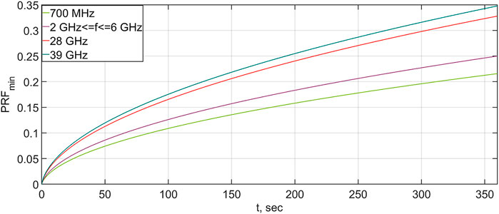
FIGURE 10. PRFmin as function of the pulse duration for some selected frequencies. For PRF values equal to or above PRFmin, compliance with the whole-body time-averaged limits (over 30 min) inherently ensures compliance with the limits on brief exposure.
While PRFmin depends on the pulse duration, Figure 10 shows that for any possible pulse at frequencies between 2 and 6 GHz, compliance with the incident power density reference levels applicable for whole-body exposure, time-averaged over 30 min, ensures compliance with the limits on energy density (for brief exposure) for PRF equal to or larger than 0.25. The corresponding PRF values for 700 MHz, 28 and 39 GHz are 0.22, 0.33, and 0.35, respectively.
Figure 10 is limited to pulse durations of 6 min since brief exposure limits are limited within this time interval. As the averaging time applicable to whole-body exposure is 30 min, pulses of longer durations are possible but the energy delivered within any integration interval between 0 and 360 s is still inherently compliant with
Note that PRFmin is determined by directly comparing the maximum possible energy in a pulse, as allowed by the whole-body reference levels, with the energy density limits intended for local exposure, without considering the difference in the applicable spatial averaging areas. Since for macro base stations (see Sections 4.1, 4.2), power density at the compliance distance is typically uniform over the whole-body surface (or line), the effect of spatial averaging can be considered negligible. At short distances from a BS, where the field distribution is more complex, or in general if the power density is not uniform over the averaging area, the criteria on PRFmin are still applicable, if compliance with the whole-body reference levels is determined without applying spatial averaging over the whole-body surface.
When applying the basic restrictions below 6 GHz, the ratio between whole-body SAR (SARwb) and local SAR (over a 10 g mass, SARlocal) normalized to their respective limits (i.e., the exposure ratios) provides additional insights to study the relevance of the brief exposure limits on EMF compliance for BS. For this purpose, the ratio
is plotted in Figure 11 as the function of the separation distance for three BS models, one at 2.6 GHz and two at 3.5 GHz. The simulated BSs correspond to two mMIMO products characterized by an array of 96 dipoles with 45-degree slant for both simulated frequencies and 64 patch arrays (8 × 8) at 3.5 GHz. SAR is assessed in the box-shaped child phantom specified by IEC 62232 (0.96 m × 0.233 m × 0.15 m) using CST Studio Suite. The antenna model is placed in parallel with the phantom, and their centers are aligned. For separation distances below 1.5 m, in order to accurately characterize the possible interactions between the antenna and the phantom, full-wave simulations based on the Finite Integration Technique (FIT) are conducted. At larger distances, a hybridization of FIT and Method of Moments (MoM) is used to reduce the simulation time, similarly to the procedure described in (Cimala et al., 2013). For the hybrid approach, the MoM is used to calculate the fields surrounding the space of the phantom, and the equivalent field source is computed on the exterior of a box slightly larger than the phantom. The whole-body averaged SAR and 10g SAR inside the phantom are solved using the equivalent field source with FIT. SARwb is obtained by dividing the total absorbed power computed with CST by a mass of 12.5 kg, as specified by (IEC, 2017). Figure 11 shows that
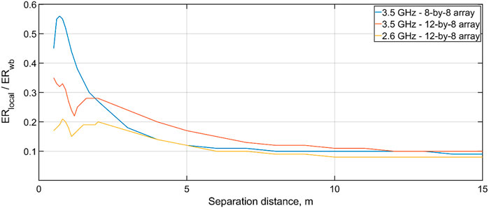
FIGURE 11. Ratio between peak-spatial localized SAR (SARlocal) and whole-body SAR (SARwb) normalized to their respective limits, as a function of the separation distance for mMIMO BS antennas at 2.6 and 3.5 GHz.
PRFmin (e.g., 0.25 between 2 and 6 GHz) values are determined for the extreme case of a BS delivering the highest possible energy in any time interval, when subject to the limit values applicable for whole-body exposure. Such a condition is implausible, since it implies that the BS transmits at peak power continuously for 6 minutes. For mMIMO products this is even more unlikely because, over time, the energy will be spread over different beams. Therefore, in realistic scenarios, compliance with the brief exposure limits is met when complying with the limits for whole-body exposure for PRFs much smaller than PRFmin. As described in (IEC, 2021), the values of PRFmin derived with Eq. 8 have to be considered as an extreme bound, for which compliance with the brief exposure limits in ICNIRP 2020 is inherently met in any possible condition, including cases that are only theoretically conceivable.
When assessing the BS compliance boundary according to the actual maximum transmit power, the availability of software features, supporting the BS scheduler and able to monitor and/or control the time-averaged transmit power during operation, might be required. Such systems can allow to set the desired time-averaging window (Törnevik et al, 2020) over which the power is controlled. By reducing the time-averaging window, e.g., from 30 to 6 min, inherently compliance with the brief exposure limits is obtained for lower PRFmin, while still ensuring compliance with the 30 min whole-body reference levels. For instance, the resulting PRFmin given by Eq. 8 when using an averaging window of 6 min is 0.045 at frequencies between 2 and 6 GHz. The corresponding PRF values for 700 MHz, 28 GHz, and 39 GHz are 0.03, 0.09, and 0.1, respectively. By reducing the averaging window, the maximum energy intrinsically allowed by the whole-body reference levels 7) becomes, for large enough t, smaller than what allowed by the brief exposure limits. Therefore, the maximum pulse duration t in expression 8) is limited to intervals below 360 s, resulting in a lower PRFmin.
Discussion
In this study, the implications of the RF EMF limits specified in ICNIRP 2020 are investigated by analyzing the compliance boundary for several BSs, including passive multi-column antennas as well as mMIMO BS, representative of different mobile technologies (from 2G to 5G) and spanning over several bands. The compliance boundaries are derived individually for each product and their dimensions are compared to those established using ICNIRP 1998. While product compliance testing for the placing of BSs on the market is conducted for the BS individually, as presented in Section 4, for putting into service (i.e., product installation compliance), the total RF EMF exposure from all antennas and technologies (2G, 3G, 4G, and 5G) on a site has to be considered (IEC, 2017). While the overall compliance boundary dimensions for installations with co-located antennas therefore might be different than what presented in Section 4, the same considerations are valid. In particular, a BS site characterized by multiple antennas which is compliant with ICNIRP 1998 remains compliant when applying ICNIRP 2020.
Within some meters from the BS, the effect of the environment on the incident power density is small and the BS compliance boundaries derived in free space are deemed to be accurate (IEC, 2017). For RF exposure evaluations conducted at large distances from the BS, in areas accessible by the general public and characterized by exposure levels typically well below the limit, the effect of scatterers and reflectors might be relevant. Within cluttered environments, the local power density levels might be larger than the spatial averaged one, due to the effects of fading. Since ICNIRP 2020 reference levels for local exposure are higher than what is applied according to ICNIRP 1998, the new guidelines could result in a smaller exposure ratio (the ratio of the exposure metric and the relevant exposure limit) for these regions. Future complementary studies, based on measurements of the RF EMF exposure directly in-situ, could be conducted to verify the findings on the implications of ICNIRP 2020 on the total exposure ratio.
The results presented in Section 4.3 for frequencies above 6 GHz are derived from the reference levels. Consolidated measurements and numerical methods addressing the basic restrictions above 6 GHz, i.e., absorbed power density, for the purpose of evaluating EMF compliance, are in fact not yet available. Few initial studies, e.g. (Diao et al, 2020) and (Samaras et al., 2021), have proposed calculation schemes and an experimental approach, respectively, but standardized procedures for the assessment of absorbed power density currently do not exist. In addition, while in close proximity of a BS antenna, the compliance boundary assessed using the reference levels below 6 GHz might lead to overly conservative results, at higher frequencies the difference when using the two metrics is expected to be smaller. The localized absorbed power density is directly related to the incident power density by the reflection coefficient of the exposed object. As ICNIRP 2020 reference levels above 6 GHz are derived by scaling of the basic restriction, assuming normal incidence on a multi-layer tissue model, the compliance distance obtained using the two set of limits is expected to be comparable. Nevertheless, while the same conclusions drawn from Section 4.3 based on the reference levels are expected to hold true when applying the basic restrictions, further investigations might be needed.
According to ICNIRP 2020, the reference levels cannot be used in the reactive near-field region at frequencies above 2 GHz and compliance need to be assessed by means of the basic restrictions. As a guide, ICNIRP identifies the minimum distance for which reference levels should be used as λ/2π but it also clarifies that “information from a technical standards body designed to specify external exposures for each EMF source type to more adequately match the basic restrictions, should be utilized to improve reference level assessment procedures.” As the latest draft of IEC 62232 (IEC, 2021) also identifies λ/2π as the practical boundary for the reactive near-field region, this is plotted in Figure 12 for all antennas operating frequencies, as selected in Section 4. These values range from about 6.5 cm at 728 MHz down to about 1 mm at 38.5 GHz. For micro and macro BS the compliance distance is determined at larger distances than λ/2π and the restrictions on the applicability of the reference levels are therefore not relevant. Even in the back of the antenna, where a BS can be ‘touch compliant’, the distance from the radiating elements to the outer surface of the radome is typically larger than the reactive near-field boundary specified by ICNIRP 2020. Therefore, it is concluded that incident power density is still relevant to assess EMF compliance for macro and micro base stations. For low power products operating below 6 GHz, testing is often conducted based on SAR measurements, and the reference levels don’t need to be used. Within the millimeter wave bands, λ/2π is below 2 mm (e.g., 1.7 mm at 28 GHz) and the usage of incident power density is therefore not precluded for practical assessment.
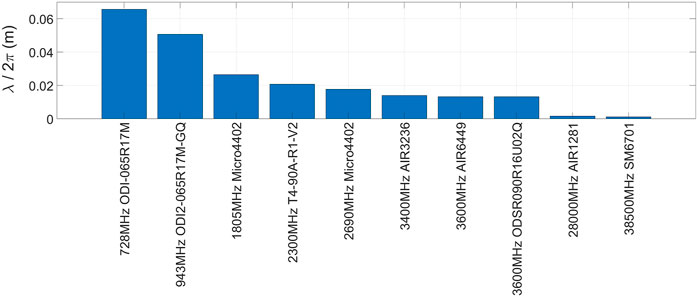
FIGURE 12. Reactive near-field boundaries for the BSs antennas selected in Section 4.
Conclusion
In this work, an analysis of the implications that the recently updated RF EMF exposure guidelines by ICNIRP have on EMF compliance of BSs has been conducted. A few changes are introduced by ICNIRP 2020 with respect to the 1998 version of the guidelines, and their impact on EMF compliance of BSs is marginal. In particular, BSs currently in operation and compliant with ICNIRP 1998 remain compliant with ICNIRP 2020.
For macro BS, the compliance boundary dimensions applicable for the general public remain substantially unchanged, if assessed using ICNIRP 2020 and compared with ICNIRP 1998. This is valid for mMIMO products as well as multi-column passive BS antennas, when using the theoretical as well as the actual maximum transmitted power (i.e., when factoring time averaging in the compliance evaluation). With ICNIRP 1998, the same limit value is used to address both localized and whole-body exposure when applying the reference levels, while separate spatial-average and spatial-peak incident power density (or field strength) limits are provided by ICNIRP 2020. Because of this, the compliance boundary height might be slightly reduced, when applying ICNIRP 2020 compared to ICNIRP 1998. The same is observed in the front and on the side of BS antennas at low power levels but the averaging effect is negligible at power levels of 40 W and above. That is, already few meters from the BS, the power density is relatively uniform over the averaging points and peak power density provides an accurate (not overly conservative) estimate of the compliance distance. In this study, spatial averaging is applied over lines corresponding to the height of the child phantom specified in IEC 62232 (IEC, 2017) and is therefore conservative for adult exposure. Averaging schemes for larger surfaces or body heights might lead to a further reduction in the compliance distance. A similar effect may be observed when assessing the compliance boundary for occupational exposure, obtained at a closer distance from the BS for which the effect of spatial averaging might be more relevant.
ICNIRP 2020 extends the validity of the whole-body SAR limits up to 300 GHz. As a result, whole-body exclusion criteria based on SAR will apply also at mmW. Therefore, for mMIMO BSs operating below 1 W (which are common in these bands), compliance is based on the local reference levels only, leading to a shorter compliance distance compared to ICNIRP 1998. Above 1 W, the compliance distance for mMIMO mmW BSs is deemed to remain unchanged.
For indoor low-power BS, the low EIRP leads to exclusion zones which extend only up to a few centimeters. For these, no difference in the compliance distance between ICNIRP 2020 and ICNIRP 1998 is expected below 6 GHz. At mmW, and for transmitted power levels of about 30 mW and above, ICNIRP 2020 results in shorter compliance distances than ICNIRP 1998. Below 30 mW, the differences between ICNIRP 1998 and the ICNIRP 2020 compliance distances is to be evaluated cases by case based on the antenna design due to the different averaging areas applicable for local exposure.
Standardization committees, such as IEC TC106, have developed exposure assessment methodologies for mMIMO BS by considering that antenna patterns are changing rapidly during operation, and beams are formed to optimize the transmission towards the served devices. Due to beam-steering, the maximum time-averaged power per beam is lower than the instantaneous rated maximum and the ratio between these two is often referred to as power reduction factor (PRF). Previously established PRFs based on 6-min time averaging (or over shorter times at higher frequencies, e.g., about 2 min at 30 GHz), are conservative with respect to the 30 min whole-body averaging interval specified within ICNIRP 2020. Therefore, PRFs for BS described in the standards and documented in literature are still applicable for assessing compliance with ICNIRP 2020 whole-body limits.
ICNIRP 2020 introduces brief exposure limits applicable for localized exposure and for integration intervals below 6 minutes. Since for BSs, EMF compliance is typically limited by whole-body exposure, compliance with the local restrictions, including those on brief intervals is met implicitly. The Committee Draft for Voting of IEC 62232 Ed3 (IEC, 2021) provides simple (but very conservative) criteria to ensure inherently compliance with ICNIRP 2020 brief limits, when compliance with the time-averaged whole-body limits (over 30 min) is met. Such criteria are given in terms of minimum PRFs and are presented in the paper.
Exposure assessments of BS are typically conducted outside the reactive near-field region of the antenna, where incident power density or field strength limits (i.e., the reference levels) apply. The only exception might be for very low power BS operating below 6 GHz, for which compliance is typically assessed based on SAR. Therefore, the restrictions introduced by ICNIRP 2020 on the region of validity for the reference levels have no practical impact on the applicability of existing EMF compliance assessment methodologies for BS.
Data Availability Statement
The original contributions presented in the study are included in the article/Supplementary Materials, further inquiries can be directed to the corresponding author.
Author Contributions
Conceptualization, all.; methodology, DC and BX; formal analysis, DC, BX, DS and CT; writing-original draft preparation, DC; writing-review and editing, all. All authors have read and agreed to the published version of the manuscript.
Conflict of Interest
Authors DC, BX, DAS, PJ, FG, CD and CT are employed by company Ericsson AB.
Publisher’s Note
All claims expressed in this article are solely those of the authors and do not necessarily represent those of their affiliated organizations, or those of the publisher, the editors and the reviewers. Any product that may be evaluated in this article, or claim that may be made by its manufacturer, is not guaranteed or endorsed by the publisher.
Supplementary Material
The Supplementary Material for this article can be found online at: https://www.frontiersin.org/articles/10.3389/frcmn.2022.744528/full#supplementary-material
Footnotes
1The whole-body exclusion criteria discussed in Section 4.2 are also valid below 6 GHz (as the whole-body SAR, limit given by ICNIRP, 2020 is the same from 100 kHz to 300 GHz). Base stations characterized by power levels equal to or lower than 1 W (or 3.68 W for installations where only the adult mass is considered) are inherently compliant with whole-body SAR.
References
ARPANSA, (2021). Standard for Limiting Exposure to Radiofrequency Fields – 100 kHz to 300 GHz. Available at: https://www.arpansa.gov.au/sites/default/files/rps_s-1.pdf.
Cimala, C., Clemens, M., Hansen, V., Spathmann, O., Streckert, J., Timm, T., et al. (2013). High Resolution Numerical Electromagnetic Dosimetry Simulations Using a Coupled Two-step Approach. IEEE Trans. Magn. 49 (5), 1633–1636. doi:10.1109/tmag.2013.2241040
Colombi, D., Thors, B., and Tornevik, C. (2015). Implications of EMF Exposure Limits on Output Power Levels for 5G Devices above 6 GHz. IEEE Antennas Wireless Propagation Lett. doi:10.1109/lawp.2015.2400331
Diao, Y., Rashed, E. A., and Hirata, A. (2020). Assessment of Absorbed Power Density and Temperature Rise for Nonplanar Body Model under Electromagnetic Exposure above 6 GHz. Phys. Med. Biol. doi:10.1088/1361-6560/abbdb7
He, W., Xu, B., and Yao, y. (2020). Implications of Incident Power Density Limits on Power and EIRP Levels of 5G Millimeter-Wave User Equipment. Piscataway: IEEE Access.
ICNIRP (2020b). 5G, Radiofrequency - RF EMF. Available at: https://www.icnirp.org/en/applications/5g/5g.html (Accessed January 26, 2022).
ICNIRP (2020c). Differences between the ICNIRP 2020 and Previous Guidelines. Available at: https://www.icnirp.org/en/differences.html (Accessed January 26, 2022).
ICNIRP (2020a). Guidelines for Limiting Exposure to Electromagnetic fields (100 kHz to 300 GHz)”, International Commission on Non-ionizing Radiation Protection (ICNIRP), Health Physics. Available at: https://www.icnirp.org/en/activities/news/news-article/rf-guidelines-2020-published.html (Accessed January 26, 2022).
ICNIRP (1998). Guidelines for Limiting Exposure to Time-Varying Electric, Magnetic, and Electromagnetic fields (Up to 300 GHz). International Commission on Non-ionizing Radiation Protection. Health Phys. 74, 494–522.
IEC (2019). Case Studies Supporting IEC 62232 – Determination of RF Field Strength, Power Density and SAR in the Vicinity of Radiocommunication Base Stations for the Purpose of Evaluating Human Exposure”. Geneva: IEC 62669.
IEC (2021). Committee Draft for Voting: Determination of RF Field Strength, Power Density and SAR in the Vicinity of Base Stations for the Purpose of Evaluating Human Exposure”. Geneva: IEC 62232.
IEC (2017). Determination of RF Field Strength, Power Density and SAR in the Vicinity of Base Stations for the Purpose of Evaluating Human Exposure”. Geneva: IEC 62232.
Samaras, T., Christ, A., and Kuster, N. (2021). Compliance Assessment of the Epithelial or Absorbed Power Density below 10 GHz Using SAR Measurement Systems”. Hoboken: Bioelectromagnetics.
Thors, B., Colombi, D., and Ying, z. (2016). Exposure to RF EMF from Array Antennas in 5G Mobile Communication Equipment”. Piscataway: IEEE Access.
Thors, B., Tornevik, C., and Colombi, D. (2017). Time-averaged Realistic Maximum Power Levels for the Assessment of Radio Frequency Exposure for 5G Radio Base Stations Using Massive MIMO”. IEEE Access.
Törnevik, C., Torjorn, W., and Shiguang, s. (2020). Time Averaged Power Control of a 4G or a 5G Radio Base Station for RF EMF Compliance”. Piscataway: IEEE Access.
Vasiliadis, T. G., Demitrious, A, G., and Sergiadis, D. G. (2005). A Novel Technique for the Approximation of 3-D Antenna Radiation Patterns. Piscataway: IEEE Transactions on Antennas and Propagation. doi:10.1109/tap.2005.850752
Keywords: 5G, base stations, mobile technologies, ICNIRP, RF EMF compliance
Citation: Colombi D, Xu B, Anguiano Sanjurjo D, Joshi P, Ghasemifard F, Di Paola C and Törnevik C (2022) Implications of ICNIRP 2020 Exposure Guidelines on the RF EMF Compliance Boundary of Base Stations. Front. Comms. Net 3:744528. doi: 10.3389/frcmn.2022.744528
Received: 20 July 2021; Accepted: 06 January 2022;
Published: 04 March 2022.
Edited by:
Rosdiadee Nordin, Universiti Kebangsaan Malaysia, MalaysiaReviewed by:
Chee Yen (Bruce) Leow, University of Technology Malaysia, MalaysiaChiara Lodovisi, Consorzio Nazionale Interuniversitario Per Le Telecomunicazioni, Italy
Copyright © 2022 Colombi, Xu, Anguiano Sanjurjo, Joshi, Ghasemifard, Di Paola and Törnevik. This is an open-access article distributed under the terms of the Creative Commons Attribution License (CC BY). The use, distribution or reproduction in other forums is permitted, provided the original author(s) and the copyright owner(s) are credited and that the original publication in this journal is cited, in accordance with accepted academic practice. No use, distribution or reproduction is permitted which does not comply with these terms.
*Correspondence: Davide Colombi, ZGF2aWRlLmNvbG9tYmlAZXJpY3Nzb24uY29t