 Ziang Yang
 Haobo Zhang1
 Hongliang Zhang
- 1State Key Laboratory of Advanced Optical Communication Systems and Networks, School of Electronics, Peking University, Beijing, China
- 2Advanced Institute of Information Technology, Peking University, Hangzhou, Zhejiang, China
- 3Peng Cheng Laboratory, Shenzhen, Guangdong, China
Integrated sensing and communication (ISAC) is an essential technology in the upcoming 6G network, and its performance can be effectively enhanced by the reconfigurable intelligent surface (RIS). Among the various RIS-enabled ISAC techniques, RIS-enabled sensing-assisted communication has attracted growing attention because it can effectively improve communication performance by focusing the energy on the sensed locations of the users and is easy to be integrated into existing communication systems. However, existing RIS-enabled sensing-assisted communication systems rely on antenna arrays for the acquisition of angular information to localize the users, making the system more complex and expensive. To handle this problem, in this paper, we propose an RIS-enabled multi-user sensing-assisted communication framework where a single antenna access point (AP) first senses the locations of the single-antenna users with the help of the RIS, and then the energy of the communication signal is focused on the sensed locations of the users to provide them with a higher sum-rate by adjusting the phase shifts of the RIS. However, the selection of the RIS phase shifts heavily influences the resource block and power allocation at the AP, which makes the joint design of the RIS phase shifts and the resource allocation very challenging. In order to address this challenge, we formulate an RIS-enabled multi-user communication optimization problem and design a two-stage optimization algorithm based on the genetic and Lagrangian duality methods to jointly optimize the RIS phase shifts and the resource allocation. Simulation and experimental results show that compared with the scheme without RIS, the proposed RIS-enabled multi-user communication system can achieve a higher sum-rate and lower localization error.
1 Introduction
In future 6G networks, the escalating demand for wireless applications, such as high-speed communication and precise sensing, is rapidly depleting spectrum resources, resulting in a scarcity of available spectrum. In order to alleviate this problem, integrated sensing and communication (ISAC) is recently proposed (Zhang, 2022). Specifically, ISAC utilizes a single set of hardware to generate signals for both sensing and communication. The obtained sensing and communication data can be further utilized to optimize the system’s overall performance, resulting in a higher communication rate and sensing accuracy. By applying the ISAC technique, the need for additional spectrum resources can be effectively reduced, and the hardware costs, power consumption, and signaling latency caused by the exchange of communication and sensing information are also minimized. In Mealey (1963), the authors first proposed the concept of ISAC, where the radar pulses were utilized for transmitting information. The OFDM technique was first introduced into ISAC signaling scheme in (Sturm and Wiesbeck, 2011). The authors in (Cui et al., 2021) first formally gave the definition and scope of ISAC.
Among various ISAC techniques, sensing-assisted communication is a promising technique, for it can not only be easily integrated into existing communication systems but also effectively improve communication performance with the help of the sensed location information. In the literature, different types of sensing-assisted communication systems have been discussed. Specifically, authors in Wu et al. (2020) proposed a two-stage hybrid beamforming technique assisted by location information to provide high-quality downlink communication services for UAVs. In Liu et al. (2020), first, the extended Kalman filter (EKF) was utilized to predict the positions of vehicles, then a power allocation method was proposed based on the position information to perform accurate beamforming. In Mahabal et al. (2022), the authors utilized the unscented Kalman filter (UKF) to estimate the positions of the vehicles, which was further utilized in the beamforming algorithm to provide better vehicle-to-vehicle communication.
As the wireless channels in the aforementioned works are passively adopted which results in limited performance, reconfigurable intelligent surfaces (RISs) are introduced in the sensing-assisted communication systems to actively customize the wireless environment for performance improvement (Zhang et al., 2022a). Specifically, an RIS is a planar surface comprising numerous RIS elements integrated with PIN diodes. By modulating the states of the PIN diodes, the RIS elements can manipulate the phase shifts of the signals that they reflect, thus shaping the radio waves impinging upon the RIS (Yang et al., 2022). In this way, the wireless environment can be controlled to provide the UEs with a higher communication rate. For example, the authors in Sankar et al. (2021) proposed an adaptively partition method of the RIS elements to simultaneously achieve high-quality communication and accurate sensing. In Wang et al. (2022), the authors minimized the multi-user interference by optimizing the transmitted waveform and the phase shift of the RIS under the Cramér-Rao bound constraint. Several RIS-enabled sensing-assisted communication systems have been discussed in the literature. Specifically, in Xing et al. (2021), the authors proposed a worst-case robust beamforming optimization problem with the help of the derived channel state information (CSI) error bound considering the RIS. An improved communication quality can be achieved by solving the formulated optimization problem. The work (Liu et al., 2022) first estimated the position of the user by solving the time of arrival (TOA) and angle of arrival (AOA) from the received signal. Then a beamforming method enabled by the RIS was designed based on the estimated position to provide the user with a higher achievable rate. However, the aforementioned works rely on the antenna array to acquire the angular information for the localization of the users, making the system more expensive and complex.
In this paper, we propose an RIS-enabled sensing-assisted multi-user communication system without the use of complex antenna arrays. Specifically, the system is composed of a single-antenna access point (AP), several single-antenna user equipments (UEs), and an RIS. The AP first localizes the UEs by analyzing the received signal with the help of the RIS. Then, based on the estimated positions of the UEs, the RIS phase shift and the power and resource block (RB) allocation matrices are optimized to focus the energy on the UEs. As a result, the communication quality of the UEs can be improved with the help of the position information.
Two new challenges have arisen in the proposed RIS-enabled sensing-assisted multi-user communication system. The first challenge lies in the way of collaboration among the AP, the RIS, and the UEs to ensure that the position information can be effectively utilized to improve communication performance with the help of the RIS. Secondly, the joint design of the RIS phase shifts and resource allocation is very challenging because the resource block and power allocation at the AP are greatly influenced by the selection of the RIS phase shifts. In response to these challenges, we make the following contributions.
• We propose the RIS-enabled multi-user communication protocol where the AP, the UEs, and the RIS cooperate with each other and provide the UEs with better communication quality with the help of the position information of the UEs.
• We formulate the optimization problem which maximizes the sum-rate of the UEs by optimizing the RIS phase shifts and the orthogonal frequency division multiple access (OFDMA) resource allocation. To solve this problem, we decouple it into two sub-problems and design a phase shift and resource allocation optimization algorithm to iteratively optimize the phase shifts and allocate the power and RB of the transmitted signal.
• We validate the performance of the proposed RIS-enabled multi-user communication framework through simulation and experiment. Both the simulation and experiment results show that the proposed scheme can achieve a higher sum-rate and lower localization error compared with the non-RIS scheme.
The rest of the paper is organized as follows. In Sec. 2, we first describe the RIS-enabled multi-user communication scenario, and then introduce the RIS model and received signal model. An RIS-enabled multi-user communication protocol is designed in Section 2. In Section 4, the phase shift and resource allocation optimization problem formulation is presented. In Section 5, the phase shift and resource allocation optimization algorithm is designed to solve the proposed problem. The simulation and experimental results are provided in Section 6 and Section 7, respectively. Finally, we draw the conclusions in Section 8.
2 System model
In this section, we first present the RIS-enabled multi-user communication scenario, and then introduce the RIS model and the received signal model, respectively.
2.1 RIS-enabled sensing-assisted multi-user communication scenario
As shown in Figure 1, we consider an RIS-enabled sensing-assisted multi-user communication system in a room that consists of I UEs, an AP, and an RIS with its controller. Each UE or the AP is equipped with a transmit antenna and a receive antenna, and the UEs communicate with the AP by using the OFDMA technique. We assume that all the UEs move in a plane with the size gx × gy, which is referred to as the space of interest (SOI), where gx and gy denote the lengths of the SOI along the x and y axes, respectively. The SOI is discretized into U = Ux × Uy square grids with the same size which is denoted by
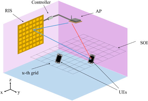
FIGURE 1. RIS-enabled sensing-assisted multi-user communication scenario.
In the proposed scenario, the AP adaptively improves the communication quality of the UEs with the help of the RIS and the estimated positions of the UEs. Specifically, when communicating with the AP, the UEs also estimate the channel responses by using received signals. The estimated responses are then sent to the AP, which is utilized to improve the localization accuracy of the UEs. Based on the estimated locations with higher accuracy, the AP can further optimize the phase shifts of the RIS to promote overall communication quality.
2.2 RIS model
The RIS is a planar material that consists of many RIS elements. Each RIS element is sub-wavelength and contains electrically controllable components such as PIN diodes (Zhang et al., 2022b). By applying different voltages to the PIN diode, it can be switched to two states: ON and OFF states, which enables the RIS element to change the phase shifts of the signals that pass by it. As a result, the RIS can focus the energy on the desired positions by carefully designing the phase shifts of all the elements in the RIS, thereby customizing the electromagnetic environment and benefiting the RIS-enabled multi-user communication system.
In this paper, we assume that the RIS consists of N RIS elements. Each RIS element has E possible phase shifts, and the difference between two neighboring phase shifts is Δξ = 2π/E. Thus, the phase shift of the n-th RIS element can be expressed as (Hu et al., 2020)
where en ∈ {1, 2, …, E}.
2.3 Received signal model
In this subsection, we model the signals received by the UEs. Assume that the OFDM signal has Ks subcarriers, and the subcarriers are divided into K groups, each assigned to one resource block (RB) with time slot duration T. Note that as the subcarriers in the same RB are adjacent, the frequency differences among them are small. Thus, we can assume that their channel responses are the same and equal to the channel response of the center subcarrier in the RB. Assume that the frequency interval between the center frequency of two adjacent RBs is Δf, the center frequency of the k-th RB can be denoted by fk = fc + (k − (K + 1)/2)Δf, where fc is the carrier frequency. Suppose that the AP communicates with the UEs over L slots, and let
where gi,l,k denotes the response of the direct channel between the AP and the i-th UE, bi,l,k,n denotes the response of the channel from the AP to the i-th UE via the n-th RIS element, Pl,k denotes the power allocated to the k-th RB, wl,k denotes the complex Gaussian white noise with mean 0 and variance σ2. Following (Goldsmith, 2005), gi,l,k can be given by
where GT and GR denote the transmit and receive antenna gains, respectively. λk denotes the wavelength of the center frequency subcarrier of the k-th RB, pUE,i and pAP denote the positions of the i-th UE and the AP, respectively. c denotes the speed of light. Besides, following (Zhang et al., 2021), bi,l,k,n can be given by
where r ∈ [0, 1] denotes the reflection amplitude of the RIS elements, and ξl,n denotes the phase shift of the n-th RIS element during the l-th slot.
3 RIS-enabled sensing-assisted multi-user communication protocol
In this section, we propose an RIS-enabled sensing-assisted multi-user communication protocol where sensing is utilized to assist multi-user communication, as is illustrated in Figure 2. The protocol contains two phases: the initialization phase and the localization and communication phase. In the initialization phase, the AP informs the UEs about the beginning of the communication process and initializes the parameters of the communication system. In the localization and communication phase, the RIS phase shifts, the power allocation, and the RB allocation are adaptively optimized based on the estimated positions of the UEs to increase communication quality. Note that during the localization and communication phase, the AP continuously communicates with the UEs. As a result, the localization and communication phase will not introduce extra delay into the communication between AP and the UEs.
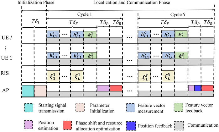
FIGURE 2. RIS-enabled sensing-assisted multi-user communication protocol.
3.1 Initialization phase
The initialization phase lasts for δI slots. First, the AP broadcasts the starting signal to the I UEs to inform all the users that the communication process begins. Then, the AP initializes the system parameters by randomly generating the RB allocation matrix
3.2 Localization and communication phase
In the localization and communication phase, the UEs communicate with the AP while the AP estimates their positions with the help of the RIS and optimize their communication performance through adjusting the phase shift vectors of the RIS. The localization and communication phase is divided into S cycles. In each cycle, the communication between UEs and the AP is continuous while the localization of the UEs is divided into three steps: feature vector measurement, position estimation, and phase shift and resource allocation optimization.
3.2.1 Feature vector measurement
The feature vector measurement lasts for δF slots. First, the AP transmits a sequence of L = δF − 1 slots. The phase shifts of the RIS are adjusted during the transmission, and the UEs record the corresponding channel responses. Specifically, during the l-th slot, the RIS phase shift vector changes to
3.2.2 Position estimation
The position estimation step lasts for δP slots. In this step, the AP first calculates the radio map
where
where
3.2.3 Phase shift and resource allocation optimization
In the last δR slots of the s-th cycle, the RB allocation matrix
4 Phase shift and resource allocation optimization problem
In this section, we first propose the phase shift and resource allocation optimization problem where the positions of the UEs are utilized to improve communication quality. Then, we decompose the proposed problem into two subproblems: the RIS phase shift vector optimization and the resource allocation optimization subproblems.
4.1 Problem formulation
The aim of the optimization problem in the s-th cycle is to maximize the expected data rate of all the I UEs in the next cycle by optimizing the RIS phase shift vector, the RB allocation matrix, and the power allocation matrix. As the optimization of the phase shift and resource allocation in different slots are independent, the phase shift and resource allocation in different slots can be optimized separately. Below we give the phase shift and resource allocation optimization problem for the l-th slot of the s-th cycle.
where
where
where Γ ≥ 1 is the gap from the channel capacity due to a practical modulation and coding scheme.
Constraint (9b) means that the value of the RIS phase shift can only be selected in a discrete set, where
4.2 Problem decomposition
Since the phase shift vector
4.2.1 RIS phase shift vector optimization
Given power allocation matrix
4.2.2 Resource allocation optimization
Given RIS phase shift vector
5 Phase shift and resource allocation algorithm design
In this section, a phase shift and resource allocation algorithm is designed to solve the above optimization problems. Specifically, we first describe the RIS phase shift vector optimization algorithm to solve (P2) in Section 5.1, then in Section 5.2, the resource allocation optimization algorithm is given to solve (P3). Finally, the overall phase shift and resource allocation algorithm is described in Section 5.3.
5.1 RIS phase shift vector optimization
To tackle (P2) which is non-convex, the RIS phase shift vector optimization problem is designed based on genetic algorithm (GA) (Whitley, 1994), which solves the optimization problem by simulating the process of natural selection. At the beginning of the GA, we randomly choose M phase shift vectors to initialize the population set
Selection: In this step, the adaptability is calculated for each individual in
After the calculation of the individual adaptabilities, Me individuals with the highest adaptabilities are selected as elite individuals, which are denoted by
Gene cross: In this step, new child individuals are generated from existing individuals by exchanging their genes. The gene cross step consists of (M − Me)/2 cycles. In each cycle, first, two individuals are selected from
Gene mutation: In this step, the genes of each child individual mutate with a predetermined small probability pm. Specifically, for each gene of each child, it may change to a random gene enΔξ, en ∈ {1, 2, …, E} at probability pm. After the mutation, the child individual set
After C cycles, the adaptabilities of the individuals in the current group are calculated and the individual with the highest adaptability is chosen as the RIS phase shift optimization result. The procedures of the RIS phase shift vector optimization algorithm are summarized in Algorithm 1.
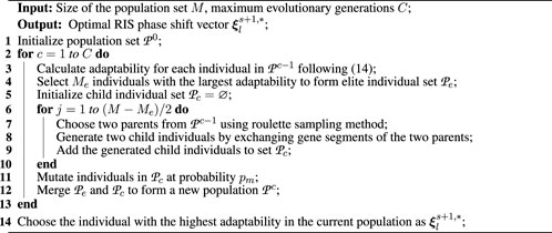
Algorithm 1. RIS phase shift vector optimization algorithm
5.2 Resource allocation optimization
A resource allocation optimization algorithm based on the Lagrange duality method is designed in this subsection to solve (P3), which first gives a dual problem of the original problem, and then solves this problem that is easier to be tackled. The Lagrange dual problem can be given by
where μ = [μ1, …μI], μ and η are called dual variables, and the Lagrangian function
Since (P3) satisfies the time-sharing condition (Yu and Lui, 2006), the duality gap between (P3) and its Lagrange dual problem (P4) is approximately zero for a sufficiently large number of subcarriers. Therefore, the optimal solution of (P3) can be well approximated by the solution of (P4). (P4) can be solved by iteratively solving the inner layer problem for current dual variables and the outer layer problem through updating the dual variables. The procedures of the resource allocation algorithm are summarized in Algorithm 2. Below we first describe the optimization of the inner layer problem. Subsequently, the optimization of the outer layer problem is presented.
5.2.1 Inner layer problem optimization
The inner layer problem in the q-th iteration can be written as
According to (Xiao et al., 2015), (P5) can be decomposed into K subproblems and optimized separately. The k-th subproblem of (P5) can be given by.
Proposition 1: The optimal power allocation solution
Let
Proof: See Appendix A.
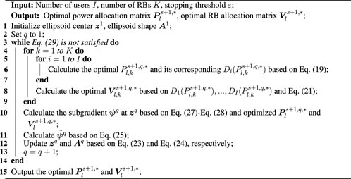
Algorithm 2. Resource allocation optimization algorithm
5.2.2 Outer layer problem optimization
After performing the aforementioned inner layer problem optimization, we can get the optimal
where zq denotes the center of the ellipsoid, and Aq denotes the shape of ellipsoid. Note that z1 and A1 are chosen following (Tao et al., 2008). The center and the shape of the ellipsoid in the (q + 1)-th iteration are updated as follows (Boyd and Barratt, 2008).
The iteration between inner layer optimization and outer layer optimization stops when (Boyd and Barratt, 2008)
where ɛ is a prefixed parameter.
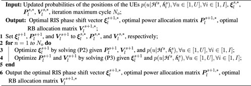
Algorithm 3. Overall algorithm in the s-th cycle
5.3 Overall algorithm
In this subsection, based on the algorithms introduced in the above two subsections, the complete phase shift and resource allocation algorithm is given. First,
6 Simulation results
In this section, we present the simulation results of the proposed RIS-enabled multi-user communication framework. The layout of the communication system in the simulation is shown in Figure 3. The size of the room is 3 × 6 m, the position of the center of the RIS is (1.5,0,0.6) m, and the position of the AP is (1.5,0.5,0.6) m. The SOI starts from 1 m to 6 m in the y direction and from 0 m to 3 m in the x direction. The size of the grid is 0.5 × 0.5m. The parameters of the simulation are provided in Table 1.
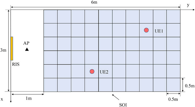
FIGURE 3. Simulation scenario.
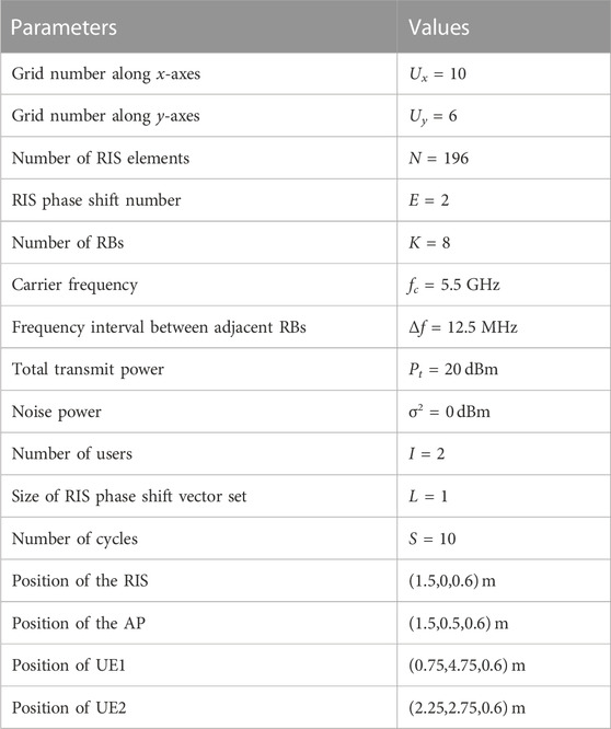
TABLE 1. Simulation parameters.
Besides the simulation results of the proposed scheme, we also provide the simulation results of the following two schemes for comparison.
• Random configuration: The RIS phase shift vector and the resource allocation matrices are randomly settled in each cycle, which can be used to verify the effectiveness of the optimization algorithm.
• Without RIS: The RIS is removed from the scenario while other settings remain unchanged, and the power and RB allocation optimization is still carried out, which can be used to show the effectiveness of the RIS.
Figure 4 shows the average localization error of the UEs versus the transmit signal-to-noise ratios (SNRs) under the above three schemes. Note that the transmit SNR is defined as the ratio of the transmit power to the environmental noise power in the dB format. It can be observed that as the SNR increases, the average localization error of the UEs decreases. This is because a higher SNR means it is easier to distinguish positions by using the received signal, leading to a lower localization error. Besides, the localization error of the proposed scheme is lower than those of the random configuration scheme and the scheme without RIS. That is because the probability that the users at each grid is updated cycle by cycle using the measured channel response. When the sum-rate is optimized, the received signal strength at the grids close to the UEs are increased. Thus, the measured channel responses at these grids are less affected by the noise, leading to better localization results.
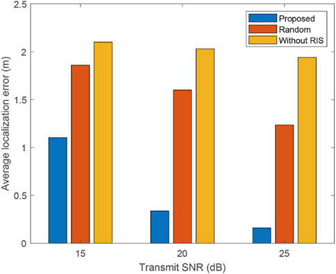
FIGURE 4. Average localization error of the UEs versus different transmit SNR.
The simulation results of the sum-rate of the UEs versus different transmit SNR under the above three schemes are given in Figure 5. We can find that the sum-rate increases as the SNR increases because a higher SNR results in improved accuracy of position estimation, enabling the RIS to efficiently focus energy on the real locations of the UEs. Besides, we can observe that the sum-rate of the proposed scheme is higher than the random configuration scheme and the scheme without RIS, which indicates that the proposed sensing-assisted communication scheme can effectively improve communication performance.
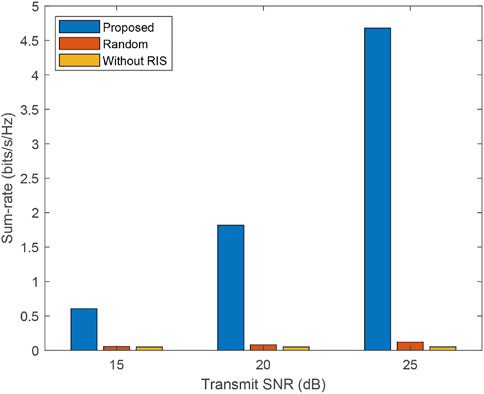
FIGURE 5. Sum-rate of the UEs versus different transmit SNR.
7 Implementation and experiment results
In this section, an experiment is conducted to validate the performance of the proposed RIS-enabled multi-user communication framework. Specifically, we first design and fabricate an RIS array, and then implement an RIS-enabled multi-user communication prototype system by using the designed RIS array. Finally, the experimental evaluation results of the prototype system are given.
7.1 RIS design
In this subsection, we first introduce the design of the 1-bit RIS element in Section 7.1.1, and then describe the design of the 28 × 28 RIS array and the corresponding experimental results in Section 7.1.2.
7.1.1 1-Bit RIS element design
Based on the frequency and bandwidth requirements in Sec. 6, we design the 1-bit RIS element. The topology of the proposed 1-bit RIS element is shown in Figure 6. The element consists of five layers: three are metallic layers and two are dielectric substrate layers. The top layer of the element contains two rectangular copper patches of different sizes which are connected by a PIN diode. To provide the PIN diode with voltage, several biasing lines are also designed on the top layer. The second layer is made of F4B. The third layer is the copper ground layer. The fourth layer is made of FR4. The last layer consists of a biasing line and a radial stub which is used for chocking the RF signal. In this paper, Skyworks SMP 1320-079LF PIN diodes are chosen for the PIN diode between the copper patches, whose equivalent circuits of ON and OFF states are shown in Figure 7.
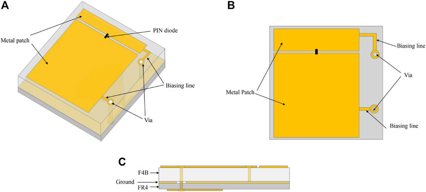
FIGURE 6. Topology of the proposed 1-bit RIS element: (A) Perspective view; (B) Top view; (C) Side view.
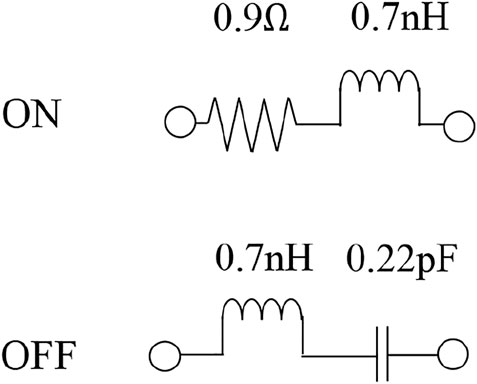
FIGURE 7. Equivalent circuits of SMP 1320-079LF.
Simulation of the RIS element is performed in CST Studio 2020 under the infinite boundary condition. Simulation results of the phase and magnitude of the S11 of the RIS element are shown in Figure 8. It can be observed that the reflection magnitudes of the ON and OFF states are both greater than 0.85. This indicates that the electromagnetic wave reflected by the RIS element will not suffer too much loss. Besides, the 180° ± 10° phase difference is achieved in the frequency range 5.45 − 5.55 GHz, which means that the center working frequency of the RIS element is 5.5 GHz and its bandwidth is 100 MHz. Thus, the simulation results can meet the frequency and bandwidth requirements in Section 6.
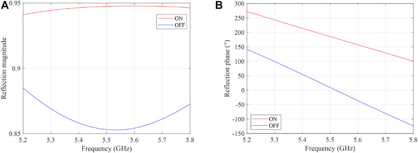
FIGURE 8. Simulated element reflection magnitude and phase: (A) Reflection magnitude versus frequency; (B) Reflection phase versus frequency.
7.1.2 28 × 28 RIS array design
Based on the designed RIS element in the previous subsection, a 28 × 28 RIS array is designed and fabricated using printed circuit board (PCB) technology. The size of the RIS array is 281 × 330 mm. In the RIS array, the neighboring 2 × 2 RIS elements are grouped as a macro-unit, and the biasing voltages applied on these elements are always the same, which means the elements in the same macro-unit are always in the same states. As a result, the RIS array consists of 14 × 14 macro-units. In order to show the ON/OFF stats of all the macro-units, we also designed a control board with light-emitting diodes (LEDs) on it. When the macro-units are in the ON state, the corresponding LEDs are on, otherwise, the corresponding LEDs are off. The RIS array and the control board are shown in Figure 9. In order to test the beamforming ability of the designed RIS array, the beam pattern of the RIS array is measured by using the vector network analyzer (VNA) Keysight E5071C, as shown in Figure 10. The angles of the main-lobes are within ±50°, and the interval is 10°. It can be observed that the RIS array can focus energy in desired directions with low side lobe level.
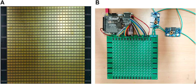
FIGURE 9. Designed RIS array and control board: (A) 28 × 28 RIS array; (B) RIS control board.
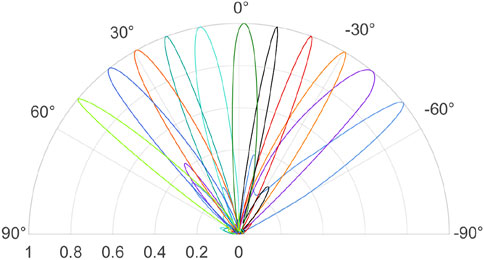
FIGURE 10. Beam pattern of the RIS array within ±50°.
7.2 Implementation of the prototype communication system
Figure 11 shows the experiment scenario with one of the UEs. The experiment is carried out in a classroom in science building #1 at Peking University. The size of the experiment scenario is 3 × 6 m and the SOI is 3 × 5 m. A chair and a desk are placed in the classroom as obstacles. The RIS and its controller are fixed on an acrylic bracket and placed in one side of the classroom. The AP consists of a universal software radio peripheral (USRP), an antenna, and a next unit of computing (NUC). Specifically, the antenna is fixed in front of the RIS by using a tripod and is connected to USRP LW-N321 which generates the transmitted signal. Besides, a NUC with Intel® Core® i5-1135G7 is utilized to control the USRP and the RIS. Each of the UEs consists of a robot car, an antenna, a USRP, an uninterruptible power supply (UPS), and a NUC. The robot car is utilized to carry the components of the UE. The antenna collects the received signal and sends it to the USRP LW-N310 which further sends the received signal to the NUC with Intel® Core ® i5-1135G7. Besides, the UPS is utilized to provide power for the UE.
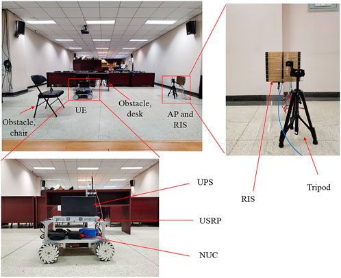
FIGURE 11. Prototype of the RIS-enabled sensing-assisted multi-user communication system.
7.3 Experimental results
In this section, we present the experimental results of the RIS-enabled multi-user communication prototype system. Similar to the simulation, the experimental result is given under the following three schemes: proposed, random configuration, and without RIS.
The average localization error of the UEs versus the number of cycles under the three schemes are shown in Figure 12. It can be observed that all the localization error first decreases and then remains unchanged as the number of cycles goes up. The localization error remains unchanged because the presence of noise disturbs the localization results. Besides, it can be found that the localization error of the proposed scheme is lower than the other two schemes. This is because through the phase shift optimization, the RIS can focus energy on the grids that are near the true position, which makes the signals measured at these grids less affected by the noise, leading to a lower localization error.
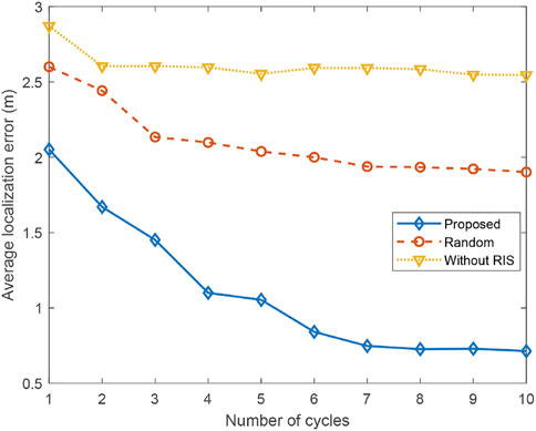
FIGURE 12. Experimental result of the average localization error of the UEs versus the number of cycles.
Figure 13 shows the sum-rate of the UEs under the aforementioned three schemes versus the number of cycles. It can be observed that the sum-rate of the proposed scheme is much higher than those of the random configuration scheme and the scheme without RIS. This means that the proposed RIS-enabled multi-user communication system can effectively improve the communication performance of the UEs. It can also be observed that the sum-rate of the proposed scheme first increase and then remains unchanged in the last four cycles because the estimated locations in these cycles are the same, leading to the same communication performances.
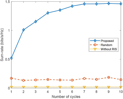
FIGURE 13. Experimental result of the sum-rate of the UEs versus the number of cycles.
8 Conclusion
In this paper, we have considered an RIS-enabled multi-user communication scenario where the locations of the single-antenna UEs are first sensed by a single-antenna AP and then utilized to improve the communication performance of the UEs. To coordinate the operations of the RIS, the AP, and the UEs, we have introduced an RIS-enabled sensing-assisted multi-user communication protocol. Based on the protocol, we have formulated the phase shift and resource allocation optimization problem to maximize the sum-rate of the UEs. To solve the optimization problem, we have designed a phase shift and resource allocation algorithm based on the genetic and Lagrangian dual methods. Simulation and experimental results validate that the RIS-enabled sensing-assisted multi-user communication system can achieve a higher sum-rate and a lower localization error compared to the multi-user communication system without the RIS. In addition, it can be concluded from the simulation and experimental results that location information can enhance communication performance by enabling the AP to accurately focus the beam on the locations of the UEs. In turn, the improved communication performance can contribute to enhancing localization accuracy, for the strength of the received signals at the grids near the real locations are increased by the optimization of the communication and the estimation of the locations is less affected by the noise.
Data availability statement
The raw data supporting the conclusion of this article will be made available by the authors, without undue reservation.
Author contributions
ZY did the simulation and experiments and wrote the article, HaZ helped with the experiments, HoZ and LS edited the article. All authors contributed to the article and approved the submitted version.
Funding
This work was supported in part by the National Key R&D Project of China under Grant 2020YFB1804800; in part by the National Natural Science Foundation Grant 62271012 and 61941101; in part by the Beijing Natural Science Foundation under Grant L212027 and 4222005; and in part by State Key Laboratory of Advanced Optical Communication Systems Networks, China.
Conflict of interest
The authors declare that the research was conducted in the absence of any commercial or financial relationships that could be construed as a potential conflict of interest.
Publisher’s note
All claims expressed in this article are solely those of the authors and do not necessarily represent those of their affiliated organizations, or those of the publisher, the editors and the reviewers. Any product that may be evaluated in this article, or claim that may be made by its manufacturer, is not guaranteed or endorsed by the publisher.
References
Bertsekas, D., and Tsitsiklis, J. N. (2008). Introduction to probability, vol. 1. Nashua: Athena Scientific.
Boyd, S., and Barratt, C. (2008). Ellipsoid method. Notes for EE364B, Stanford: Stanford University.
Cui, Y., Liu, F., Jing, X., and Mu, J. (2021). Integrating sensing and communications for ubiquitous IoT: Applications, trends, and challenges. IEEE Netw. 35, 158–167. doi:10.1109/mnet.010.2100152
Grötschel, M., Lovász, L., and Schrijver, A. (1981). The ellipsoid method and its consequences in combinatorial optimization. Combinatorica 1, 169–197. doi:10.1007/bf02579273
Hu, J., Zhang, H., Di, B., Li, L., Bian, K., Song, L., et al. (2020). Reconfigurable intelligent surface based RF sensing: Design, optimization, and implementation. IEEE J. Sel. Areas Commun. 38, 2700–2716. doi:10.1109/JSAC.2020.3007041
Lipowski, A., and Lipowska, D. (2012). Roulette-wheel selection via stochastic acceptance. Phys. A, Stat. Mechan. Appl. 391, 2193–2196. doi:10.1016/j.physa.2011.12.004
Liu, C., Hu, X., Peng, M., and Zhong, C. (2022). “Sensing for beamforming: An IRS-enabled integrated sensing and communication framework,” in ICC 2022 - IEEE International Conference on Communications, Seoul, South Korea, 16–20 May 2022, 5567–5572. doi:10.1109/ICC45855.2022.9838505
Liu, F., Yuan, W., Masouros, C., and Yuan, J. (2020). Radar-assisted predictive beamforming for vehicular links: Communication served by sensing. IEEE Trans. Wirel. Commun. 19, 7704–7719. doi:10.1109/TWC.2020.3015735
Mahabal, C., Wang, H., and Fang, H. (2022). Dual mode localization assisted beamforming for mmWave V2V communication. IEEE Trans. Veh. Technol. 71, 9450–9459. doi:10.1109/TVT.2022.3175165
Mealey, R. M. (1963). A method for calculating error probabilities in a radar communication system. IEEE Trans. Space Electron. Telem. 9, 37–42. doi:10.1109/tset.1963.4337601
Nee, R., and Prasad, R. (2000). OFDM for wireless multimedia communications. USA: Artech House, Inc.
Sankar, R. P., Deepak, B., and Chepuri, S. P. (2021). “Joint communication and radar sensing with reconfigurable intelligent surfaces,” in 2021 IEEE 22nd International Workshop on Signal Processing Advances in Wireless Communications (SPAWC), Lucca, Italy, 27-30 September 2021 (IEEE), 471–475.
Sturm, C., and Wiesbeck, W. (2011). Waveform design and signal processing aspects for fusion of wireless communications and radar sensing. Proc. IEEE 99, 1236–1259. doi:10.1109/jproc.2011.2131110
Tao, M., Liang, Y.-C., and Zhang, F. (2008). Resource allocation for delay differentiated traffic in multiuser ofdm systems. IEEE Trans. Wirel. Commun. 7, 2190–2201. doi:10.1109/TWC.2008.060882
Wang, X., Fei, Z., Huang, J., and Yu, H. (2022). Joint waveform and discrete phase shift design for RIS-assisted integrated sensing and communication system under cramer-rao bound constraint. IEEE Trans. Veh. Technol. 71, 1004–1009. doi:10.1109/TVT.2021.3122889
Wei, Z., Cai, Y., Sun, Z., Ng, D. W. K., Yuan, J., Zhou, M., et al. (2021). Sum-rate maximization for IRS-assisted UAV OFDMA communication systems. IEEE Trans. Wirel. Commun. 20, 2530–2550. doi:10.1109/TWC.2020.3042977
Wu, H., Hou, R., and Sun, B. (2020). “Location information assisted mmWave hybrid beamforming scheme for 5G-enabled UAVs,” in ICC 2020 - 2020 IEEE International Conference on Communications (ICC), Dublin, Ireland, 07-11 June 2020, 1–6. doi:10.1109/ICC40277.2020.9149027
Xiao, X., Tao, X., and Lu, J. (2015). Energy-efficient resource allocation in LTE-based MIMO-OFDMA systems with user rate constraints. IEEE Trans. Veh. Technol. 64, 185–197. doi:10.1109/TVT.2014.2319078
Xing, Z., Wang, R., Yuan, X., and Wu, J. (2021). “Location-aware beamforming design for reconfigurable intelligent surface aided communication system,” in 2021 IEEE/CIC International Conference on Communications in China (ICCC), Xiamen, China, 28-30 July 2021, 201–206. doi:10.1109/ICCC52777.2021.9580370
Yang, Y., Zhang, S., and Zhang, R. (2020). IRS-enhanced OFDMA: Joint resource allocation and passive beamforming optimization. IEEE Wirel. Commun. Lett. 9, 760–764. doi:10.1109/LWC.2020.2968303
Yang, Z., Zhang, H., Zhang, H., Di, B., Dong, M., Yang, L., et al. (2022). MetaSLAM: Wireless simultaneous localization and mapping using reconfigurable intelligent surfaces. IEEE Trans. Wirel. Commun. 1, 2606–2620. doi:10.1109/TWC.2022.3213053
Yu, W., and Lui, R. (2006). Dual methods for nonconvex spectrum optimization of multicarrier systems. IEEE Trans. Commun. 54, 1310–1322. doi:10.1109/tcomm.2006.877962
Zhang, H., Di, B., Bian, K., Han, Z., Poor, H. V., and Song, L. (2022a). Toward ubiquitous sensing and localization with reconfigurable intelligent surfaces. Proc. IEEE 110, 1401–1422. doi:10.1109/JPROC.2022.3169771
Zhang, H., Hu, J., Zhang, H., Di, B., Bian, K., Han, Z., et al. (2022b). MetaRadar: Indoor localization by reconfigurable metamaterials. IEEE Trans. Mob. Comput. 21, 2895–2908. doi:10.1109/TMC.2020.3044603
Zhang, H. (2022). Joint waveform and phase shift design for RIS-assisted integrated sensing and communication based on mutual information. IEEE Commun. Lett. 26, 2317–2321. doi:10.1109/LCOMM.2022.3195062
Zhang, H., Zhang, H., Di, B., Bian, K., Han, Z., and Song, L. (2021). MetaLocalization: Reconfigurable intelligent surface aided multi-user wireless indoor localization. IEEE Trans. Wirel. Commun. 20, 7743–7757. doi:10.1109/TWC.2021.3087354
Appendix A: Proof for proposition 1
As
As
Keywords: reconfigurable intelligent surface, OFDMA, indoor localization, sensing-assisted communication, lagrangian duality method
Citation: Yang Z, Zhang H, Zhang H and Song L (2023) Reconfigurable intelligent surface-enabled integrated sensing and communication: a sensing-assisted communication framework. Front. Comms. Net 4:1176322. doi: 10.3389/frcmn.2023.1176322
Received: 28 February 2023; Accepted: 17 April 2023;
Published: 26 May 2023.
Edited by:
Yingyang Chen, Jinan University, ChinaReviewed by:
Dayu Zhu, Georgia Institute of Technology, United StatesJue Wang, Nantong University, China
Zhiqing Wei, Beijing University of Posts and Telecommunications (BUPT), China
Copyright © 2023 Yang, Zhang, Zhang and Song. This is an open-access article distributed under the terms of the Creative Commons Attribution License (CC BY). The use, distribution or reproduction in other forums is permitted, provided the original author(s) and the copyright owner(s) are credited and that the original publication in this journal is cited, in accordance with accepted academic practice. No use, distribution or reproduction is permitted which does not comply with these terms.
*Correspondence: Hongliang Zhang, aG9uZ2xpYW5nLnpoYW5nQHBrdS5lZHUuY24=