 Kai Janning
 Sven König1
 Laura Herbst
 Bastian Nießing
 Robert H. Schmitt
- 1Department of Bioadaptive Production, Fraunhofer Institute for Production Technology IPT, Aachen, Germany
- 2Intelligence in Quality Sensing, Laboratory for Machine Tools and Production Engineering (WZL), RWTH Aachen University, Aachen, Germany
Indroduction: Personalized medical devices, especially scaffold-based implants, are increasingly important in medical care. One established manufacturing method for these products is extrusion-based 3D printing, also called 3D material extrusion (MEX) or extrusion additive manufacturing (EAM). According to the current state of the art, this technique lacks scalability, as many adjacent processes, such as material handling or quality control, are still carried out manually and no holistically automated solutions have been established.
Methods: This work examines the extrusion-based 3D printing process for manufacturing cell-free porous scaffolds. Based on a literature review, relevant process parameters for MEX and quality attributes of polymer-based scaffolds are analyzed to derive functional requirements for holistically automating the manufacturing process. A concept for an end-to-end automated production infrastructure is developed, to allow efficient and scalable manufacture of scaffolds. All process parameters are analyzed for their influence on the quality attributes, and requirements are specified. Based on this, the development of the production concept is systematically carried out.
Results: The resulting technical system consists of a magnetic planar drive, which is used as an intralogistic transport system, but also forms the horizontal axis plane of the 3D printer. The resulting frictionless levitating print bed increases cleanroom suitability and enables the parallelization of print jobs and quality control steps for improved production flexibility and scalability. The central approaches of the concept are presented in a physical demonstrator.
Discussion: An initial proof of concept for planar drive-based MEX is provided and lays the foundation for further development and validation of the conceptualized production infrastructure.
1 Introduction
The individualization of medical devices is increasing throughout medical care, such as personalized reconstructive implants and tailor-made surgical tools that are adapted to the specific anatomy of the patient. For example, the use of personalized knee implants has shown that on the one hand, the duration and costs of surgery can be reduced and, on the other hand, patient recovery and satisfaction with the surgical procedure improves (Murr, 2020). This illustrates that individualization of medical devices has advantages for the healthcare system as well as for patients. Currently, more and more polymer-based applications of individualized medical devices are being researched, such as bioresorbable scaffolds for reconstructing bone or soft tissue (Backes et al., 2022; O’Connor and Blau, 2019; Schroeder et al., 2022).
Additive manufacturing (AM) is established in research and industry as a suitable process for the production of individualized medical devices made out of polymers such as polycaprolactone (PCL), polylactide (PLA), or polylactide-co-glycolide (PLGA). Extrusion-based three-dimensional (3D) printing, also called extrusion additive manufacturing (EAM) or material extrusion (MEX) as a more general term, has become dominant due to its relatively low cost and high adaptability (Altıparmak et al., 2022). Nevertheless, according to the current state of the art, the manufacturing process is still strongly influenced by manual process steps. Processes, such as material supply, quality control, as well as the handling of final products, are carried out manually by personnel, making it difficult to scale production efficiently (Oleksy et al., 2023; Parulski et al., 2021). Growing markets for personalized medicine and the associated manufacture of individual medical devices require that the corresponding production technologies allow a higher degree of individualization while maintaining the same efficiency and staying compliant with regulations (Fairfield Market Research, 2024; Pathak et al., 2023). Therefore, scalable and automated manufacturing is required to be established to achieve a cost-efficient and large-scale production for medical care.
The aim of this work is to determine the specific requirements for a fully automated and scalable production infrastructure for personalized medical products manufactured via MEX, more specific as fused layer modeling (FLM) or fused deposition modeling (FDM®) being an established commercial name, owned by Stratasys. These terms, according to ISO/ASTM 52900:2021, describe the same technology and can be further categorized into fused filament fabrication (FFF) and fused granulate fabrication (FGF) depending on the raw material form. Development focus is set on the production of medical products using extrusion-based 3D printing. Figure 1 illustrates the product subcategories applicable to this technology. The subcategories are derived from an exploratory literature review, where both the current state of research and established industry products were reviewed. Supplementary Material S1 shows a table with the individual applications and the respective references to the literature.
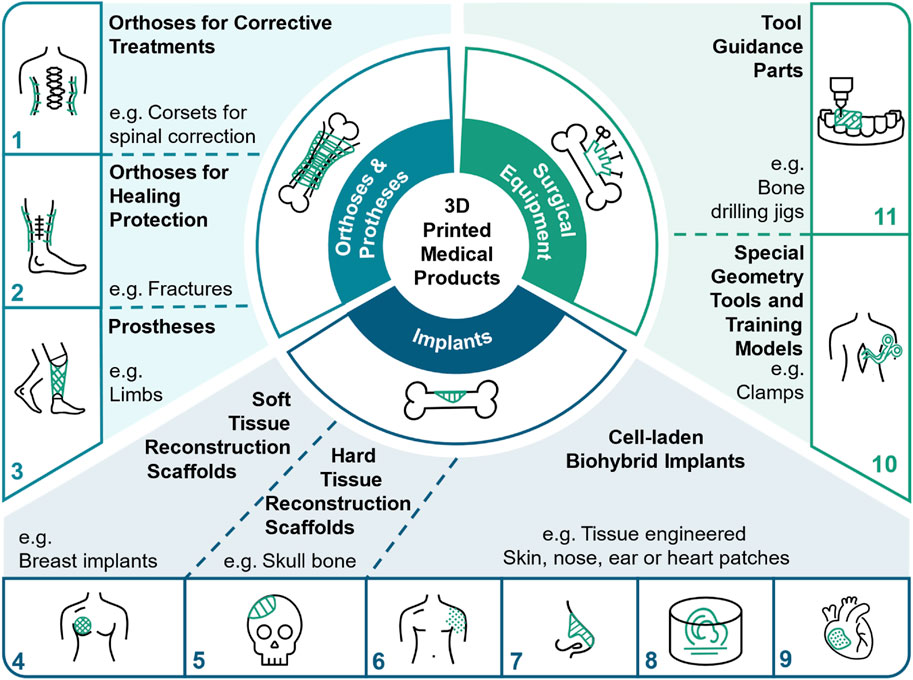
Figure 1. Sub-categorized applications for personalized 3D printed medical Products.
Compared to other established 3D printing techniques, such as selective laser sintering (SLS) or stereolithografie (SLA), MEX is often the most feasible manufacturing process for some of the above-mentioned products, like especially porous scaffolds. One reason for this is its cleanroom-compatibility, as it does not require powders or liquids and therefore ensures the use of defined material batches traceable for a respective product. In addition, the process offers material flexibility as no photoinitiators are required. MEX requires low maintenance efforts, as only nozzle changes and cartridge cleaning or replacement are necessary. Additionally, MEX is suitable for bioprinting applications as it enables the extrusion of cell infused hydrogel suspensions (Garot et al., 2021). However, in terms of automation for high-throughput manufacturing, MEX is lagging behind the SLA process, as demonstrated by insights from private-sector production lines (Formlabs, 2024). In the field of academic production technology, no established solutions have been published to the knowledge of this author. So there is a distinct research gap in relation to the design of fully automated production infrastructures for the quality-assured high-throughput manufacturing of individual medical devices, particularly with regard to MEX.
1.1 Characterization of the intended application in the medical field
This work addresses the production of patient-specific medical products as shown in Figure 1, which can serve as support structures for various medical applications, such as orthosis (Popescu et al., 2021; Redaelli et al., 2020), prosthesis (van der Stelt et al., 2021), surgical equipment (Yilmaz et al., 2019; Zaidi et al., 2021) and implants (Cheng et al., 2022; Janzekovic et al., 2022; Khalaf et al., 2022; Varpe et al., 2024).
In order to be able to develop a practical production concept and to carry out a use case-based validation, the raw material, fabrication process and product category are defined as shown in Figure 2. PCL is chosen as the raw material in a granular form. This polymer has been established for many years for medical applications, in particular as a suture or implant material (Nguyen et al., 2023; Soufivand et al., 2020). FGF is chosen for its ability to process pellets as raw material and does not require preprocessing into filaments. In addition, there are established FGF extruders that meet hygienic design standards (Justino Netto et al., 2021; Nguyen et al., 2023). Tissue reconstruction scaffolds (Figures 1, 4, 5) are selected because they represent a significant market demand among personalized medical products (Grand View Research, 2022). The term “scaffold” refers to a three-dimensional highly porous structure to be used as an implant and to grow and nest biological material (Do et al., 2015). Accordingly, only products of a certain size are relevant. The scaffolds considered, range from 10 g to 100 g with external dimensions not exceeding 100 mm * 100 mm * 50 mm. Also, only cell-free scaffolds are considered, instead of biohybrid implants. The term “cell-free” is defined here as the printed scaffold consisting exclusively of polymer and no living cells being involved in the printing process. Subsequent in vitro or in vivo colonization of the scaffold is still possible, but is not considered part of the scaffold production process.
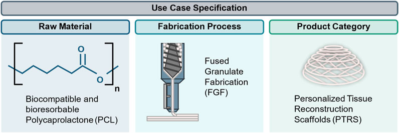
Figure 2. Specification of the use case.
1.2 Technical process requirements
While the 3D printing process itself is automated, the other steps like quality control or material handling and logistics, are dominantly manual. In the following, the manual process steps, derived from reviewing literature, are described and the requirements for the transfer into automated production are defined. The process steps relevant in this context are broken down into their main functions, as shown in Figure 3. The process derived is only applicable for single material additive manufacturing.
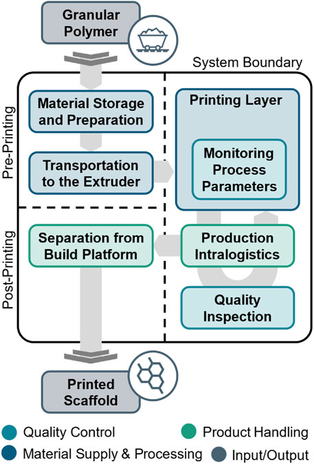
Figure 3. Basic overview of the individual process steps and their main functions from incoming material supply to outgoing finished products.
1.2.1 Material supply and processing
At the beginning of the printing process, PCL granulate is provided to the system, which includes not only the physical supply of the material but also procedures for ensuring traceability and quality assurance. This involves recording the supplier information, batch codes, and implementing incoming quality control protocols such as moisture content testing and visual inspection to ensure consistent material properties. The step of material feeding into the extruder includes three sub-functions. First, sufficient quantities of the raw material must be stored under controlled environmental conditions. Due to the hydrophilie of PCL, it must be stored in a cool (<5°C) and low-humidity place to prevent moisture absorption and in a dark and closed vessel to prevent premature degradation. The granules are conveyed from storage to the extruders granulate reservoir, from where they are transferred to the hot end and melted for product forming. The granules should not remain in the uncooled extruder reservoir for more than 2 weeks, as otherwise, properties may change due to degradation. The product shaping is realized with an extruder forcing the melted polymer through a nozzle. This requires the synchronous control of the nozzle temperature, the extrusion rate and the three mechanical axes as well as optionally further vents for cooling the printed layer.
1.2.2 Quality control
The necessary quality controls for medical devices are divided into pre-production, in-production and post-production steps. Before production, for example, incoming material inspections or, in general, the validation of the individual processes is necessary. These are covered by the manufacturer’s quality assurance system. Post-production controls can include randomized 100% inspections, which, for example, include destructive mechanical testing. For the design of the production infrastructure within this work, only the in-production quality controls are considered. These are divided into two categories:
Monitoring critical process parameters: Process parameters need to be recorded and documented for each product. For the specified use case this includes extrusion rate and extrusion temperature.
Verifying critical quality attributes: The attributes of each product need to be verified. For the specified use case dimensional accuracy of the printed layers, the porosity of the scaffold and the linkage between the layers are controlled. Therefore, tolerable thresholds must be defined for these attributes. The measured data is used for documentation, quality assessment and process adjustments.
1.2.3 Product handling
Product handling describes the transport of the components between workstations. This includes transporting the printed object from the extruder to the quality control stations, storing the printed product in a storage area, and handling the substrate plates on which the product is printed. Due to the scalability and efficient resource utilization, specific stations within the whole system are to be used by several extrusion units if they only account for a small proportion of the total production time. This particularly affects the quality inspection with its often expensive metrology, as well as the separation stations, which are required once at the end of each printing process. Once a product is completed, it is separated from the build platform and transported to the designated storage location where it can be received by employees. This exceeds the system boundary shown in Figure 3. In addition, it must be possible to remove faulty objects, which have failed one of the quality controls and restart the same print job subsequently. Removing the product from the build platform can be a critical step, as this is where damage can be introduced into the product after the end of the printing process.
1.3 Performance requirements
The automation concept to be developed is intended to contribute to a fast, cost-efficient and quality-assured supply of individualized medical devices. Appropriate technical approaches are therefore characterized by the fulfillment of a number of requirements, which impact the production performance or are derived from regulatory guidelines (Schuh and Funk, 2019). The requirements are briefly summarised below and illustrated in Supplementary Material S4.
1.3.1 Regulatory Compliance for medical cleanroom production
Medical devices that come into contact with human tissue are subject to high standards of hygiene and sterility, which is why they are manufactured under strict cleanroom conditions (Schuh and Funk, 2019). As part of the conceptual design, it must be ensured that automation approaches are suitable for use in cleanrooms and follow hygienic design principles. The most common practice to ensure this is to comply with Good Manufacturing Practice (GMP) guidelines, whereby legally binding requirements specific for the country of approval must be met. These are specified, for example, by the Medical Device Regulatory (MDR) in Europe and by the Food and Drug Administration (FDA) in America. Along with this, the entire production must operate with a certified quality management system (Martinez-Marquez et al., 2019; Lhotská et al., 2019; Schuh and Funk, 2019).
1.3.2 Autonomy during production
An advantage of automating the entire process chain is the dectease of personnel costs while maintaining consistent product quality. To run the process safely and autonomously, elements for process monitoring and inline quality control are required. The accurate and instantaneous collection of process data allows for reactive and optimized control of process parameters, improving product quality and reducing process errors. Any developed automation concepts must be robust against possible malfunctions, e.g., faulty prints should not require manual intervention. The system must be able to detect malfunctions, react to them and, ideally, resume production independently.
1.3.3 Flexibility and scalability for adaptable manufacturing
The production is targeted to produce individualized medical scaffolds in a dynamic and demand-oriented manner, which requires flexibility instead of linear process chains. A functional design should enable the system to serve different production quantities while using the same technical components. Existing systems should be expandable at a later date with little effort. Particularly expensive devices like extruders should be optimally utilized to avoid unproductive downtime. The customization of individual medical products to patient-specific features requires batch-size-one production while maintaining high throughput. The solution concepts must therefore be able to adapt to different product geometries automatically. A key feature of flexible production is the ability to maintain operability when individual devices break down.
1.3.4 Integrability for the 3D printing process
The selection of solution concepts must take into account the extent to which the identified approaches are compatible with existing solutions and can be integrated into process workflows. Suitable solution concepts are characterized by a system design, which allows an integration of different or additional devices, for example, a specific quality control. For the interfaces between the defined sub-functions, it is crucial that they are compatible between adjacent process steps. This applies to both hardware and software interfaces. Individual modules of the 3D printing system should not interrupt or otherwise influence the production process. The assessment of integrability includes an economic comparison between the approaches. If the value of the approaches is the same, the most cost-effective solution is chosen.
2 Methodology
2.1 Development approach for production system design
The development procedure for the technical solution concept is based on the established VDI Guideline 2221 (Justino Netto et al., 2021; VDI, 1997). The applied research and development methodology consists of multiple sub-tasks and is structured as shown in Figure 4.
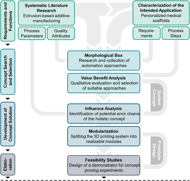
Figure 4. Research and development methodology for technical concept development, oriented according to VDI Guideline 2221.
Initially, relevant requirements and functions are identified, taking into account both process parameters and quality attributes of the product and production, which are investigated by conducting a systematic literature review. Subsequently, a comprehensive analysis of potential automation solutions is conducted, leading to the selection of a coherent solution concept. This concept is then divided into individual modules, with a systematic identification of potential influences on quality attributes. Building on this, the modules are further elaborated, and initial feasibility studies are prepared to assess the viability of the proposed solutions.
Based on the characterization of the intended application and the thereby described process steps, the basic technical requirements are derived. The associated functions are summarized in a function tree, shown in Figure 5, allowing the design and development to be more focused (Romli et al., 2013).
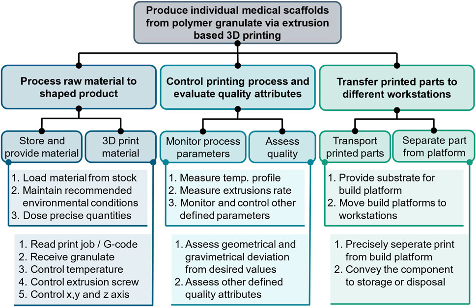
Figure 5. Representation of the function tree of the production system.
2.2 Identification, evaluation and selection of automation solutions
The overall methodology for the selection of automation solutions for the individual functions is visualized in Figure 6. The focus is set on the morphological box method for the collection and comparison of different technical approaches (Zwicky, 1967). The left column of the morphological box is formed by the function tree derived from the production process itself, described with Figure 3. Based on the functions to be fulfilled, as shown in the function tree in Figure 5, technical solution approaches are exploratively searched for in the literature. For the explorative literature research for each individual function, search criteria are chosen and both scientific and, in particular, industrial publications are considered in order to identify established solutions. During the first review, the technologies are evaluated in terms of their ability to fulfill the function. During the second review, a decision is made on whether an implementation would be realistic considering the defined use case. This variety of possible solutions fills the matrix of the morphological box, as shown in Figure 8.

Figure 6. Schematic visualization of the used morphological box method with inputs and outputs.
In the third review, a value-benefit analysis is carried out with the selected technologies, whereby a qualitative assessment is made of the extent to which the individual solutions meet the performance requirements regarding first Regulatory Compliance, second Autonomy, third Flexibility and Scalability and fourth Integrability, as shown in Chapter 1.1.3. The ratings for each performance requirement of each individual approach are shown in Supplementary Material S4. The morphological box highlights the best-rated approach. More detailed explanations regarding the selected and non-selected technologies from the explorative technology research are listed in Supplementary Material S4.
2.3 Literature review on extrusion-based additive manufacturing for medical scaffolds
The research focuses on identifying relevant process parameters and quality attributes as well as their interactions with each other according to the current state of scientific knowledge. The literature review procedure is based on the recommendations of Brocke et al. (2009). The inclusion criteria selected are briefly explained in the following: The year of publication is limited to after 2009, the year in which the patent for FDM 3D printing from Stratasys expired and the technology became open access. To ensure an accurate understanding of the literature, only publications in German or English are selected. For the publication type, reviews as well as original publications are considered for analysis. The databases “Web of Science Core Collection”, “Engineering Village (by Elsevier)” and “Embase (by Elsevier)” were chosen. These provide literature from the fields of engineering, medicine and science in general, covering the relevant research fields (Gusenbauer and Haddaway, 2020). To extract the most relevant information, subcategories with related content were first derived and then filled with search terms (vom Brocke et al., 2015, p. 215). The search terms were iteratively revised on the basis of test searches in the databases mentioned above in order to achieve the most accurate coverage of the subject area. The final search terms are shown in Table 1.
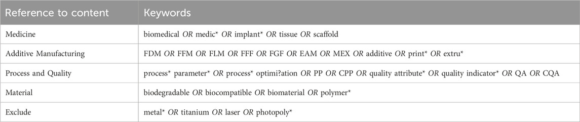
Table 1. Search terms for the literature research.
The selection process is systematized into four review stages, which sequentially evaluate more information from the publications: First, titles and key terms are checked for relevance and compliance with inclusion criteria (1844 paper). Second, abstracts and conclusions are reviewed for indications of process parameters and their impact on quality attributes, focusing on extrusion-based additive manufacturing of medical products (174 paper). Third, a full-text analysis assesses the scientific quality and information content (28 papers). Lastly, with the remaining papers, a reverse search is conducted in the bibliographies of the selected articles, leading to a total of 30 papers considered for the process analysis. These publications are listed and briefly described in Supplementary Material S2.
3 Results
3.1 Analysis on relevant process parameters and quality attributes
The review of the 30 papers resulted in the process parameters and quality attributes shown in Figure 7. Detailed references to the corresponding literature are listed in Supplementary Material S2. The process parameters are assigned to individual subcategories and relate either to temperature conditions, extrusion properties, geometry-related settings, or timing or environmental parameters. The most frequently studied process parameter in the literature is the deposition speed, followed by the extrusion temperature and the extrusion pressure, which technically achieves the same function as the extrusion rate and can therefore be equated with it.
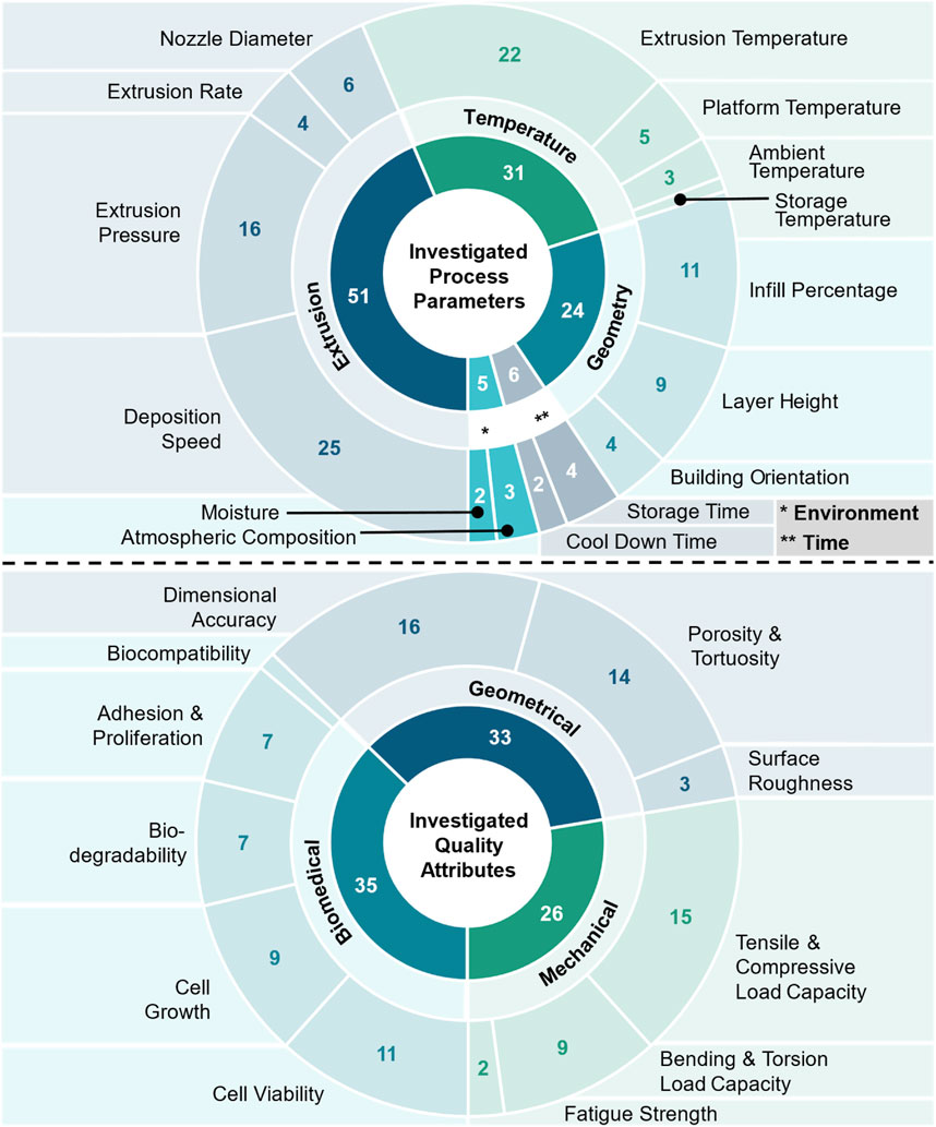
Figure 7. Investigated process parameters of MEX (above) and investigated quality attributes (below) of MEX manufactured medical scaffolds. Parameters and Attributes are listed and categorized with the number of times they occur in the reviewed literature.
The precision and performance of 3D-printed medical products depend significantly on the process parameters used during their fabrication. Proper control and optimization of these parameters ensure the desired mechanical properties, dimensional accuracy, and overall quality of the final product. The attributes by which the quality of MEX manufactured medical scaffolds can be evaluated are shown in Figure 7 as well. The categories to which the attributes can be assigned are the geometric and mechanical properties of the printed product, as well as biomedical properties, which, primarily, relate to tissue engineering respectively bioprinting products. Dimensional accuracy is the quality attribute of 3D-printed medical scaffolds that has been most extensively investigated in the literature. The tensile and compressive strength of the scaffolds is of great importance, as are their porosity properties.
Examining the researched process parameters and quality attributes shows that a fundamental distinction must be made between biohybrid products, i.e., products that include living cells, and pure cell-free structures, consisting solely of a polymer-based matrix and no additional biological material. For cell-laden products, an essential quality attribute is the viability of the printed cells, which can be influenced by almost all process parameters. All process parameters and quality attributes shown in Figure 7 are explained in detail in Supplementary Material S3. These explanations are based on the full-text analysis from which nine key publications were identified (Bahraminasab, 2020; Baier et al., 2022; Bouzaglou et al., 2023; Kovylin et al., 2021; Popescu et al., 2018; Rendas et al., 2023; Shick et al., 2019; Winarso et al., 2022; Zhang et al., 2019).
3.1.1 Critical process parameters (CPPs) and critical quality attributes (CQAs)
Depending on the specified use case only some of the identified parameters and attributes are relevant and can be defined as critical. The most frequently mentioned process parameter, deposition speed, is a parameter that can be specifically set via the 3D printer control system so that no additional monitoring is necessary. The extrusion pressure and the extrusion rate both refer to the extruded volume flow of molten polymer. The second most often mentioned process parameter is the extrusion temperature, which should therefore be monitored in this application. All other parameters shown in Figure 7 are either defined by the product or are set once in the system, such as the nozzle diameter, deposition speed, platform temperature and cool down time. While they must be validated once before production, they do not need to be monitored continuously. Others, such as the ambient temperature and humidity are monitored by the cleanroom system itself and do not require additional metrology. Table 2 highlights the process parameters critical for the specified application.

Table 2. Process parameters and quality attributes classified as relevant for the use case (CPPs and CQAs are marked in bold).
The quality attributes of the products to be manufactured, are divided into biomedical, mechanical, and geometrical attributes. Biomedical properties such as cell viability and cell growth are not relevant for the defined cell-free scaffold use case. The other biological properties like biocompatibility and biodegradability are influenced solely by the choice of material and the given geometry of the product, so that no process is necessary to control these attributes in production. The dimensional accuracy and the porosity of the finished product are critical quality attributes and must be monitored during production. The mechanical properties, such as the load capacities and the fatigue strength, derive from the connection of the individual filaments between the layers in the scaffold application. This layer linkage should be monitored during the production process. It is not possible to control the mechanical properties using compression or tensile tests, as the products are personalized scaffolds with inherently different geometries for which no target values for mechanical strength can be specified. The surface roughness attribute is not relevant for the scaffold application due to the intention of a porous surface.
The automation concept developed requires critical process parameters to be monitored and critical quality attributes to be inspected. This results in functions for which conceptual solutions are sought. The morphological box method is used for this purpose.
3.2 Derivated automation concepts
The selection of automation approaches for the solution concept is based on the results of the value-benefit analysis and is displayed in the morphological box in Figure 8. In the following, a statement is made for each decision in favor of a solution approach, while the detailed results of the value-benefit analysis are given in Supplementary Material S4. The interaction between these approaches as well as the overall production concept is explained subsequently.
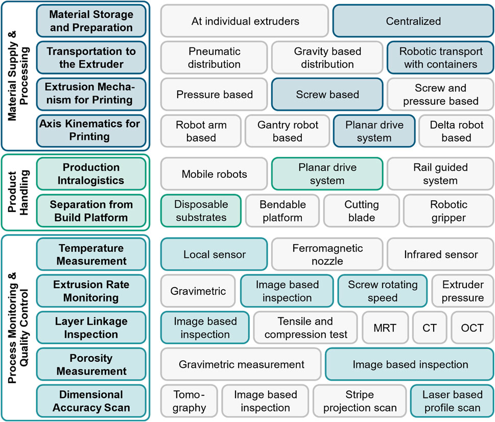
Figure 8. Morphological box with identified solution approaches evaluated according to the performance requirements.
3.2.1 Centralized material storage, preparation and transport with granulate containers
This approach involves storing the granules in a temperature-controlled central dispensing tank. An integrated dispensing system enables precise and automatic filling of transport containers in a cleanroom-compatible manner. For incoming material, the granules must be refilled manually at appropriate intervals. Commercially available solutions for different scales exist that allow the storage of several 100 kg of granulate, which would correspond to several thousand scaffolds. Such systems are well established in the plastics processing, pharma and food industries (Volkmann GmbH, 2024), which is why no further development work would be required for implementation. The degree of innovation is correspondingly low. It should be noted that a low humidity level must be guaranteed when processing PCL. The integration of a drying system is therefore recommended for maintaining predictable processability. The process parameters that are derived by this approach are the average humidity, the average storage temperature and the storage time of the granules between opening the primary packaging and the beginning of processing. Individual storage of the granulate at the extruders would have the disadvantage of increased integration effort due to individual monitoring of the storing conditions being required.
Due to the centralized supply of the granulate, an automated transport system between the dosing station and the extruder must be designed. It must be possible to adapt the system depending on the number and positioning of the extruders in operation. Flexibility is therefore necessary. A solution was chosen that involves transport containers being filled with granulate at the central dosing station and then being transported to the extruders by mobile robots. Due to the only temporary transportation in the transport containers, additional tempering of these is not considered. When using containers, it is only necessary to ensure that the surfaces that come into contact with the granules meet hygiene standards. It is not necessary to seal the containers during transportation due to the cleanroom environment, as long as the container opening is not moved below possible sources of particle abrasion. Suitable vessels of this kind are commercially available. Compatibility with the gripper of the mobile robots must be ensured.
Autonomous mobile robots for intralogistics tasks in production have already been established for a number of applications (Unger et al., 2018), as well as for more complex material handling in laboratory applications (Kleine-Wechelmann et al., 2022). Although the implementation effort is increased due to the teaching of the movements, such as filling and emptying the granulate container, and due to the training of the recognition of the dosing station and the extruder chute, this approach is particularly useful in terms of scalability and flexibility. The development effort and the degree of innovation are rated as moderate.
3.2.2 Screw based extrusion 3D printing with planar drive powered horizontal axis
For the extrusion of PCL, the melted granulate is pressed through the nozzle either by an extruder screw, by applying pneumatic pressure or by a combination of both methods. Specifically for PCL, an extruder screw is sufficient and more cost-effective than a pneumatic system. The considered process parameters of extrusion rate and extrusion temperature can be easily set for a screw-based system.
A magnetic planar drive is chosen as an unconventional approach for implementing the kinematics of the 3D printing process. In this approach, so-called movers, consisting of permanent magnet arrays, are held in magnetic levitation and can be positioned in the plane with a tolerance of 50 µm. The mover therefore acts as the build platform for 3D printing but is physically independent. In a previous publication, the industrial use of magnetic planar drives in production was discussed in detail (Janning et al., 2022). The use of a magnetic planar drive for 3D printing was first presented in 2022 within the patent WO2023094674A1. The concept was investigated and validated within the publicly funded German Bundesministerium für Bildung und Forschung (BMBF) research project “BellaFactum” (13GW0497B). The planar drive is used for the X and Y-axis for 3D printing, while the extruder is mounted on a linear electric Z-axis. The advantages of the concept are:
1. Frictionless movement and thus the minimization of particle abrasion, which increases the cleanroom suitability.
2. Direct connection to the production intralogistics and thus the possibility to decouple the printing bed from the extruder and move to another station, for example, for quality control.
3. Minimization of downtime, as multiple movers can serve one extruder. For example, while a printed layer on one mover is cooling, another layer can be printed on a second mover.
4. Scalability, as the planar drive can easily be enlarged in its surface area and throughput can be increased by adding further extruders and movers.
Due to the novelty of the approach, proofs of concept are to be provided as part of the development of the holistic solution concept, which is why the degree of innovation is classified as very high. The approach adds the mover levitation height as a potential quality influencing process parameter.
3.2.3 Planar drive-based production intralogistics
The use of a planar drive system for the kinematics of the 3D printer enables direct connection to the production intralogistics at the same time. Since the stator area can be extended as required, further processing or quality control stations can simply be docked onto the system and all transport steps can be accomplished by the planar drive. Only for special intralogistic steps such as storing finished products on shelves, multi-axis robots is required.
The planar drive with several movers is to be understood as a dynamic interconnected multi-agent transport system. Even if linear process chains can be mapped with the system, it makes sense to evaluate free-chained adaptive approaches that allow a mover different destinations to be targeted depending on the result of a quality control. Additionally, it is necessary for the logistics to react adaptively due to the personalized products and the resulting impossible preliminary scheduling of discrete process steps. The implementation of such optimized multi-agent path finding (MAPF) algorithms is currently the subject of research (Stern, 2019), but they have not yet been fully established in the industry, which is why the degree of innovation is considered to be high. Process parameters that are relevant for this internal logistics have no interface with the product itself, so they are not considered further, except for later throughput optimizations.
The individual movers of the planar drive act as the build platforms, with an exchangeable substrate plate mounted on top. On the upper surface of these substrates, the PCL is extruded on. The substrate plates are designed as disposables and, together with the finished scaffold, are considered as the final product. The separation of the scaffold and the substrate plate can be done outside of the production environment, manually at the point-of-care. Mounting on the movers can be done using suitable brackets and a robotic gripper. Suitable substrate plates for printing PCL are commercially available and do not require further engineering. The surface quality of the substrate plates is highly important for the success of the 3D print because if the adhesive properties are insufficient, warping effects (Ramian et al., 2021) can occur or the extruded layer can peel itself off the substrate during printing. The compatibility of the substrate material and the material to be printed must therefore be validated in each case. If this is the case, there are no additional influential process parameters for the production.
3.2.4 Process monitoring and quality control via local sensors and optical metrology
A local thermocouple is the most established and cost-effective solution for monitoring the nozzle and extrudate temperature, which is why this approach is chosen.
The extrusion rate can be monitored in a screw-based extruder via the screw rotational speed, given that the system is appropriately calibrated. Since air inclusions can potentially occur due to inhomogeneous granule size, and thus cause temporary extrusion interruptions, additional monitoring is required. This is done by capturing high-resolution images of the individual printed layers. Automated evaluation algorithms can be used to determine whether over- or under-extrusion has occurred. The magnetic planar drive as an intralogistics transport system allows the mover to move to a camera station to inspect a printed layer and then move back to continue the print at the extruder or to a disposal station to remove the substrate with the defect scaffold.
The cross-linking of the filaments of the individual layers can be evaluated using the same images as for extrusion monitoring. This test assumes that if the extrusion was dimensionally accurate without over- or under-extrusion, then the linking is also accurate. A 100% validation can only be carried out using tomographic methods. Magnetic Resonance Tomography (MRT) or Computed Tomography (CT) is not economically viable for this application. Optical Coherence Tomography is a possible alternative. However, it still requires additional integrative efforts compared to conventional image recordings.
The porosity of the scaffolds correlates with the density of the scaffold and is defined by the distances between the individual filaments of a layer. These filament distances are also measured using the layer geometries determined by image evaluation.
The final quality control of the scaffolds involves measuring the external dimensions. For this purpose, laser distance measurement is used to create point clouds of the external dimensions of the finished scaffold. By comparing the measured values with the planned geometries from the computer-aided design (CAD) model of the scaffold, a decision is automatically made whether or not the quality parameter for dimensional accuracy is within the tolerance range.
3.3 End-to-end automation concept for individual medical scaffold manufacturing
The combination of the individual technical approaches, described in the Chapter before, results in a holistic concept for a production infrastructure for the use case of medical personalized PCL scaffolds. The hardware set-up of this concept is shown schematically in Figure 9. The process flow is as follows: The individual movers of the magnetic planar drive (1) are loaded by the robot (8) from the substrate storage with a sterile disposable substrate. The movers, ready for printing (4), then move to the extruder (2), which is mounted on a vertical linear axis. The linear axis and the two horizontal axes of the planar drive then execute the printing paths of the individual layers during synchronous extrusion of the material. Depending on the configured cool-down time, a pause is scheduled between each layer, during which the mover moves to its home position and waits. Concerning the associated logistical processes, the extruder is initially filled with granulate by a mobile robot (6). The granulate is provided in a central reservoir including a dosing unit (7). The reservoir is cooled so that the prescribed storage conditions for the granulate are maintained. The dosing unit gravimetrically meters a defined mass of granulate into the mobile robot’s custom transport container using a screw drive. The robot can then transport the granulate to the corresponding extruder and tip it into the hopper. An ultrasonic sensor detects when the available material in the extruder falls below a certain threshold and triggers a new granulate filling process.
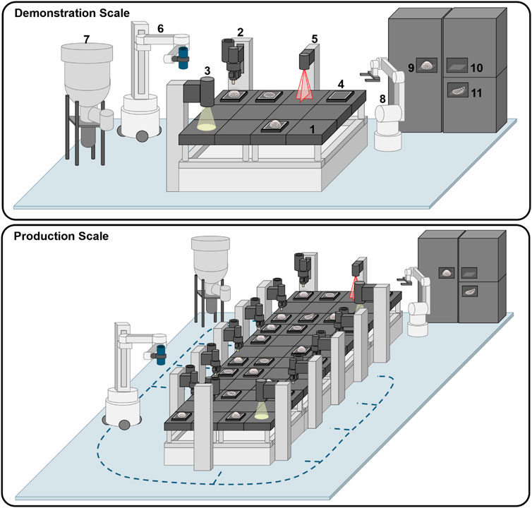
Figure 9. Production infrastructure in demonstration scale (above) and in production scale (below) for increased throughputs. 1: Planar drive system, 2: Granulate extruder including Z-axis, 3: Microscopic camera for image-based quality control, 4: Mover with mounted substrate plate, 5: Laser depth scanner for quality control, 6: Mobile robot for granulate container transport, 7: Granulate storage and dosing machine, 8: Robotic arm for product handling tasks between mover and storage, 9: Storage for finished implants, 10: Storage for ready to use substrates, 11: Storage for failed prints.
Quality control steps can be added between the fabrication of individual print layers or at the end of the printing process. The concept shown here involves moving the movers to a camera station (3) after printing a defined number of layers (n = 5), where high-resolution images of the last printed layer are taken using a reflected-light camera. These images are then used for multiple purposes: Firstly, to check the position and thickness of the printed filament lines to detect whether over- or under-extrusion has occurred. Secondly, the layer linkage is checked. Based on the shading at the intersections between horizontally and vertically placed filaments, it can be interpreted whether the filaments are fused or floating on top of each other and no layer linkage is achieved. If a defined tolerance threshold of unlinked intersections is exceeded, the print is declared defective. Thirdly, porosity is determined by measuring the distances between the filament lines and therefore interpreting the material to volume ratio.
For the final inspection, the finished scaffolds are moved to the laser depth scanner (5), where a point cloud of the scaffold is recorded in order to interpret the outer dimensions of the scaffold. This allows the detection of deformations such as warping, which can occur due to thermal stresses in the material during and after the printing process. The finished and inspected scaffolds are then returned to the separator station, where the robot arm removes the substrate plate including the scaffold from the mover and transfers it to an automated storage system (9). If a printing process has to be aborted, the substrate with the defective scaffold is transferred to a different storage location (11). The mover is then loaded with a new scaffold and the same printing process is repeated. If waiting queues occur at extruders or quality control stations, the mover with the previously failed print job is given priority. The automated process ends with the personnel filling the storage tanks with new substrate plates and removing the finished or damaged scaffolds from the storage. In addition, the central granulate reservoir is refilled manually.
The production infrastructure can be scaled in terms of throughput, which is defined as scaffolds produced per unit of time. To realize this, the surface area of the magnetic planar drive is expanded by attaching additional tiles and additional extruders, including its linear axis (compare Figure 9 below).
Concerning the software infrastructure of the concept, Figure 10 shows the connections between the individual control components and control software for the conceptualized production infrastructure. Most of the devices, such as the planar drive, linear drives, controllable extruder components, the dosing unit motors and the automated storage systems, are directly connected to the Programmable Logic Controller (PLC) in the electric cabinet. Devices such as mobile and stationary robots have proprietary controllers for operation. Although these controllers can be physically integrated into the electric cabinet, the individual motors are not controlled directly via the PLC. Other devices, such as cameras, are connected directly to a computer running a Windows© operating system and are operated using proprietary software. Other programs, such as algorithms for image evaluation, run locally on the computer via third-party software environments like Python© and can communicate with the PLC software environment. This communication between the PLC and third-party software is essential for implementing path-planning algorithms for the simultaneous coordination of all movers to avoid collisions and allow parallel adaptive processes. The PLC, other controllers and software communicate with an integration framework that provides an interface driver for each individual hardware device and enables connection to a higher-level control software. The COPE (Control Operate Plan Execute) control software is used as the overarching communication level, allowing a FDA CFR Part 11 compliant orchestration of the Production (Hort et al., 2023; Jung et al., 2018).
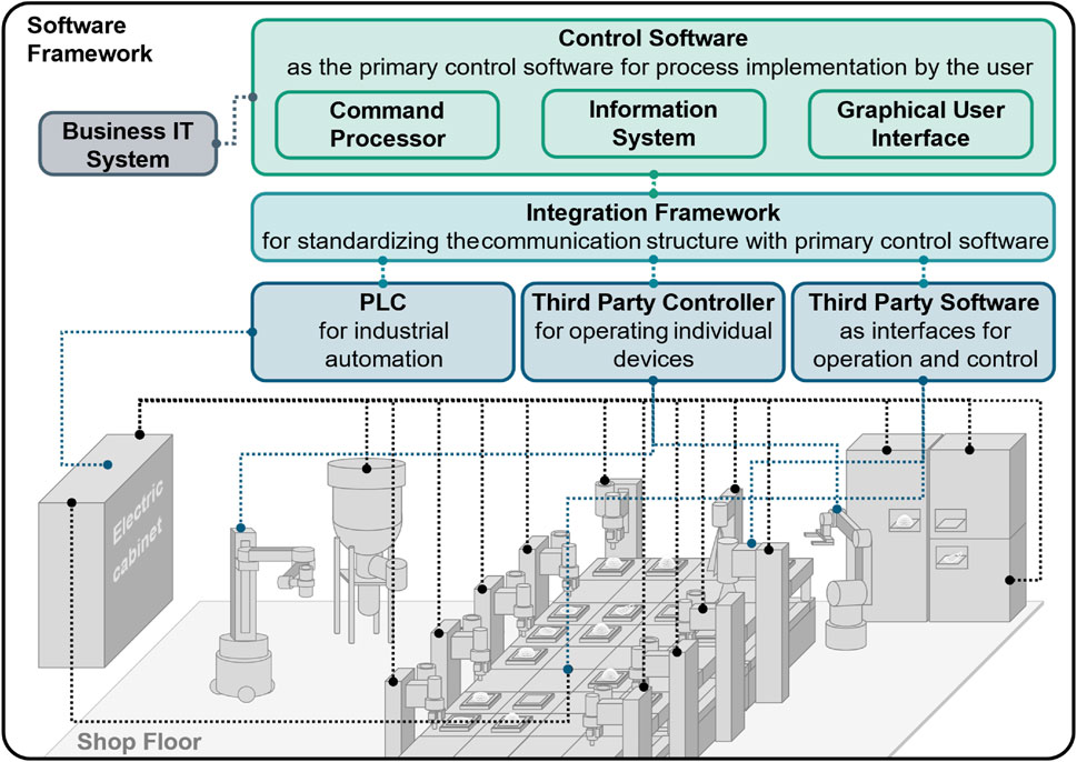
Figure 10. The conceptualized software framework for the production infrastructure with its main components.
3.4 Materials selected for concept finalization
Table 3 summarizes all the components that were considered for the finalization of the production concept and later were implemented for the construction of a validation demonstrator.
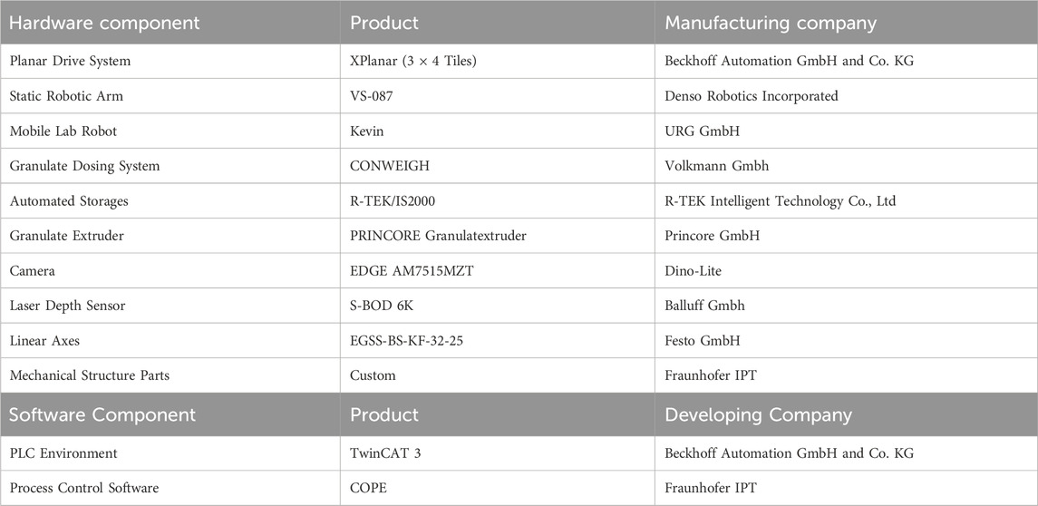
Table 3. Hardware and software components considered for concept finalization.
3.5 Prototype system for feasibility tests
For the validation of the production concept, a demonstrator system is designed and constructed. The demonstrator does not include peripheral system components, such as the mobile robot for extruder filling, the dosing machine and the storage system, as these are established commercially available technologies that do not require a demonstration of functionality. The demonstrator is described as a Dynamically Interconnected Additive Manufacturing System (DIAMS), which is defined as an automated platform that uses dynamically interconnected agents between multiple additive manufacturing and control stations to enable parallel and flexible production. Figure 11 shows the computer-aided design (A and B) and the real system set up in the laboratory (C).
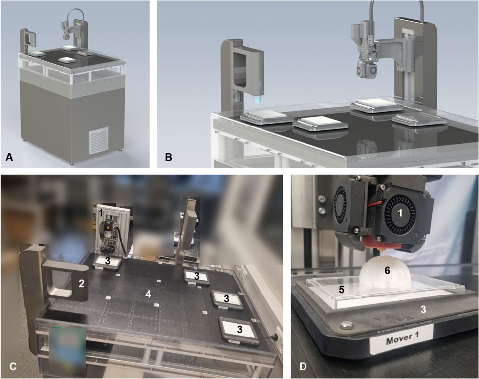
Figure 11. DIAMS demonstrator for validating the production infrastructure concept. (A,B) Computer-aided design renderings created with SolidWorks 2023®, (C) Laboratory set-up of the demonstrator, (D) Close view on extruder, mover, substrate and printed scaffold.
The system consists of a 3D printer extruder (1), a microscope camera for image recording and the planar drive (4) with four movers (3). The movers are equipped with the top lid of a standardized one-well plate made of polystyrene, which acts as the substrate (5). The scaffolds (6) are printed onto this substrate. The components are specified in Table 3 which summarizes all the components that were considered for the finalization of the production concept and later implemented for the construction of the DIAMS.
The planar drive system, which consists of three times four tiles, each measuring 240 mm * 240 mm, can independently levitate four movers, each measuring 155 mm * 155 mm and position them planarly with a precision of up to 50 µm. The movers were set to a levitation height of 2 mm. The control cabinet for the planar drive is located below the planar drive. The camera and the extruder are each mounted on a motor-driven linear axis that is located on the side of the planar drive. The axes motors, as well as the end stop sensors, the extruder motor and its temperature sensor and its fans, are connected to the same control cabinet. All devices are controlled via the TwinCAT automation software. A MAPF algorithm was written in Python for parallel, flexible control of the movers. This algorithm is based on model-based predictive control with the conflict-based search for collision-free pathfinding. A function for synchronous axis control was implemented in TwinCAT that reads the GCode, used in 3D printing, and extracts and transfers the corresponding coordinates to the axes of the planar and linear drive. By using the parameter set recommended by the extruder manufacturer, all hardware and software requirements for 3D printing are implemented.
3.6 Proof of principle
To verify general feasibility of the concept, initial tests were carried out to determine the suitability of the planar drive-based extrusion additive manufacturing (PEAM) for 3D printing , shown in Figures 12A, B. The test object shown in Figures 12C–E is a scaffold cuboid with external dimensions of 50 mm * 50 mm * 20 mm and a layer height of 200 μm, which was printed five times using the PEAM. A 400 µm nozzle was used, extruded at 130°C nozzle temperature, with a deposition speed of 15 mm/s. The measured outer dimensions of the square base area are on average 49.8 mm ± 0.2 mm. For the height, an average value of 19.9 mm ± 0.1 mm was measured. When examining the scaffold structure, an increased occurrence of the stringing effect was observed, indicating further parameter optimization might be required to increase printing quality in future research. Overall, the proof-of-principle on general printability of the DIAMS was successful, as the system was able to print a test objects without significant shape deviations from the CAD file.
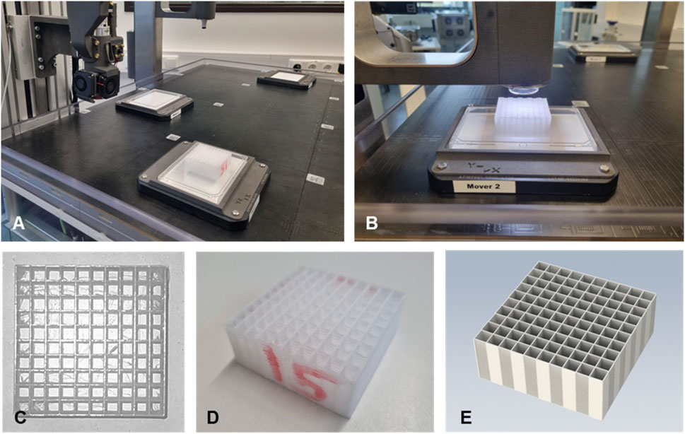
Figure 12. Printing experiment of a test scaffold using PEAM. General set-up of PEAM with a scaffold on a polystyrene substrate on a mover (A), scaffold under the image-based QC station (B), captured image of the scaffold from a top view (C), finished scaffold (D) and rendering of the computer-aided design reference scaffold body (E).
4 Critical discussion
The systematic literature review on extrusion-based 3D printing and its process parameters reveals that while a broad overview exists, completeness is uncertain due to the sheer volume of publications. However, it is reasonable to conclude that all most relevant parameters for the use case of PCL based scaffolds have been identified, although less common technologies like FGF extruder systems may be underrepresented. The automation concept was developed using established engineering methods and exploratory searching for suitable solutions for the automation of individual processes. This approach cannot assure that all technologies have been considered equally. Evaluations were based on qualitative performance criteria and surveying experts, lacking quantitative assessments of technical parameters, and economic evaluations remain qualitative without concrete data. The iterative approach allows for post-evaluation modifications, yet the completeness and optimality of selected solutions are not guaranteed. The conceptual system is limited to the use of PCL-based porous scaffolds for tissue reconstruction. Only products in the size range of 10–100 g and with external dimensions not exceeding 100 mm * 100 mm * 50 mm were considered. For larger products, a redesign of the system is necessary. Moreover, validation experiments only utilized uniform cuboid scaffolds, complicating automatic image data evaluation for more complex, personalized geometries. Validation focused on a first proof-of-principle for the PEAM approach, potentially overlooking technical challenges within the general automation concept due to the lack of comprehensive practical validation of the whole production infrastructure.
5 Conclusion
Based on a literature review of extrusion-based medical 3D printing and the definition of the use case on personalized medical scaffolds, a requirement profile for a scalable automated production infrastructure was created. The individual process steps were analyzed and characterized in terms of their functionalities. For the individual functions, automation approaches were collected using the morphological box method and evaluated using a utility analysis. The sum of the highest-rated approaches in each case formed the holistic production concept. This was analyzed with regard to possible impairment of product quality and finalized. The concept was then divided into realizable development modules, which were elaborated and physically implemented in the form of a demonstrator (DIAMS). DIAMS represents the key functions of the production concept. This demonstrator is capable of moving several print beds, which are carried by levitating movers, dynamically and independently, frictionless above the platform. The movers are realizing both the 3D printing movements in horizontal X and Y directions and the transport between extruder and an imaging station. Accordingly, online quality controls can be scheduled in between the printing of the individual layers. DIAMS was successfully used to print first test scaffolds with a maximum shape deviation of 0.4 mm to demonstrate general printability.
6 Outlook
The conceptualized production infrastructure specializes in the use case of manufacturing personalized medical scaffolds made of PLC using FGF 3D printing. The transferability to other use cases must be individually re-evaluated. In principle, the production concept can be applied to other products that are manufactured using MEX. The infrastructure brings advantages such as cleanroom suitability, which is specifically relevant for the medical sector but offers no added value for other, less regulated product classes. The concept appears to be most advantageous for 3D printed products that are subject to high-quality standards and require integrated quality control. Especially for individual products without standardized geometries, the flexibility of the production concept is beneficial.
Whether the advantages of the concept persist must be individually evaluated. The targeted production throughputs influence the techno-economic advantage of the developed concept. Further simulation studies are to show specifically for which production scenarios the developed production infrastructure has advantages compared to classic 3D printer farms.
Looking ahead, work should be continued by carrying out in depth feasibility studies and a validation. Particular attention should be paid to the development of a digital model of the production infrastructure in order to identify techno-economic potential with regard to throughput scaling and layout optimization. For this model, a discrete-event simulation could be designed, which can be parameterized with real data obtained from the physical demonstrator.
Another field of research that should be investigated in depth is adaptive process control in multi-agent systems. In the developed production infrastructure, solving the MAPF problem is essential for dynamic control of the system. There are various approaches for this, with model predictive control (MPC) being the current state of research. In the following work, various models, such as conflict-based search (CBS) can be integrated at the demonstrator system and investigated. The aim of the investigations is to establish suitable models for resource-efficient path planning in dynamically interconnected AM systems (DIAMS).
Data availability statement
The original contributions presented in the study are included in the article/Supplementary Material, further inquiries can be directed to the corresponding author.
Author contributions
KJ: Conceptualization, Data curation, Investigation, Methodology, Project administration, Supervision, Validation, Visualization, Writing – original draft, Writing – review and editing. SK: Conceptualization, Investigation, Methodology, Visualization, Writing – review and editing. LH: Project administration, Supervision, Writing – review and editing. BN: Funding acquisition, Resources, Writing – review and editing. RS: Resources, Writing – review and editing.
Funding
The author(s) declare that no financial support was received for the research and/or publication of this article.
Conflict of interest
The authors declare that the research was conducted in the absence of any commercial or financial relationships that could be construed as a potential conflict of interest.
Generative AI statement
The author(s) declare that Generative AI was used in the creation of this manuscript. The author(s) verify and take full responsibility for the use of generative AI in the preparation of this manuscript. Generative AI was used for linguistic corrections and formulation assistance as well as for translations from German into English.
Publisher’s note
All claims expressed in this article are solely those of the authors and do not necessarily represent those of their affiliated organizations, or those of the publisher, the editors and the reviewers. Any product that may be evaluated in this article, or claim that may be made by its manufacturer, is not guaranteed or endorsed by the publisher.
Supplementary material
The Supplementary Material for this article can be found online at: https://www.frontiersin.org/articles/10.3389/fmtec.2025.1572842/full#supplementary-material
References
Altıparmak, S. C., Yardley, V. A., Shi, Z., and Lin, J. (2022). Extrusion-based additive manufacturing technologies: state of the art and future perspectives. J. Manuf. Process. 83, 607–636. doi:10.1016/j.jmapro.2022.09.032
Backes, E. H., Harb, S. V., Beatrice, C. A. G., Shimomura, K. M. B., Passador, F. R., Costa, L. C., et al. (2022). Polycaprolactone usage in additive manufacturing strategies for tissue engineering applications: a review. J. Biomed. Mater. Res. - Part B Appl. Biomaterials 110 (6), 1479–1503. doi:10.1002/jbm.b.34997
Bahraminasab, M. (2020). Challenges on optimization of 3D-printed bone scaffolds. Biomed. Eng. Online 19 (1), 69. doi:10.1186/s12938-020-00810-2
Baier, R. V., Contreras Raggio, J. I., Giovanetti, C. M., Palza, H., Burda, I., Terrasi, G., et al. (2022). Shape fidelity, mechanical and biological performance of 3D printed polycaprolactone-bioactive glass composite scaffolds. Biomater. Adv. 134, 112540. doi:10.1016/j.msec.2021.112540
Bouzaglou, O., Golan, O., and Lachman, N. (2023). Process design and parameters interaction in material extrusion 3D printing: a review. Polymers 15 (10), 2280. doi:10.3390/polym15102280
Brocke, J., Simons, A., Niehaves, B., Niehaves, B., Reimer, K., Plattfaut, R., et al. (2009). Reconstructing the giant: on the importance of rigour in documenting the literature search process. ECIS 2009 Proc. 161. Available online at: https://aisel.aisnet.org/ecis2009/161 (Accessed June 10, 2025).
Cheng, M. E., Janzekovic, J., Theile, H. J., Rutherford-Heard, C., Wille, M.-L., Cole, C., et al. (2022). Pectus excavatum camouflage: a new technique using a tissue engineered scaffold. Eur. J. Plastic Surg. 45 (1), 177–182. doi:10.1007/s00238-021-01902-5
Do, A.-V., Khorsand, B., Geary, S. M., and Salem, A. K. (2015). 3D Printing of Scaffolds for Tissue Regeneration Applications. Adv. Healthc. Mater. 4 (12), 1742–1762. doi:10.1007/s00238-021-01902-5
Fairfield Market Research (2024). 3D printed medical implant market: global 3D printed medical implant industry analysis, size, share, growth, trends, and forecast 2023-2030 - (By material coverage, by application coverage, by geographic coverage and by company). Fairfield Market Research. Available online at: https://www.fairfieldmarketresearch.com/report/3d-printed-medical-lmplant-market (Accessed June 10, 2025).
Formlabs (2024). Berechnung des ROI für das automatisierte Ecosystem von Formlabs. Formlabs. Com. Available online at: https://3d.formlabs.com/white-paper-calculating-roi-for-the-formlabs-automation-ecosystem/ (Accessed June 10, 2025).
Garot, C., Bettega, G., and Picart, C. (2021). Additive manufacturing of material scaffolds for bone regeneration: toward application in the clinics. Adv. Funct. Mater. 31 (5), 2006967. doi:10.1002/adfm.202006967
Grand View Research (2022). Scaffold technology market size, share and trends analysis report by type: hydrogels, polymeric scaffolds, by disease type (cancer, neurology), by application, by end-use, by region, and segment forecasts, 2023 - 2030. Grand View Research. Available online at: https://www.grandviewresearch.com/industry-analysis/scaffold-technology-market# (Accessed June 10, 2025).
Gusenbauer, M., and Haddaway, N. R. (2020). Which academic search systems are suitable for systematic reviews or meta-analyses? Evaluating retrieval qualities of Google Scholar, PubMed, and 26 other resources. Res. synthesis methods 11 (2), 181–217. doi:10.1002/jrsm.1378
Hort, S., Sanges, C., Jacobs, J. J., Hudecek, M., and Schmitt, R. H. (2023). Digital transformation of CAR-T cell therapy – challenges and potential for Industry 4.0. Procedia CIRP 120, 1034–1040. doi:10.1016/j.procir.2023.09.121
Janning, K., Niessing, B., Koenig, N., and Schmitt, R. H. (2022). Reibungsloser 2D-Produkttransport mit magnetischen Planarantrieben: Reine Magnetschwebetechnik. A&D Automation and Digitalisierung, 54–58. Available online at: https://www.industr.com/de/A-und-D-Magazin/_storage/asset/2672958/storage/master/file/23104159/E-Paper_A&D_Nov22.pdf (Accessed June 10, 2025).
Janzekovic, J., Hunt, J., Peltz, T., Wagels, M., Brown, T., and Hutmacher, D. W. (2022). Biomechanical principles of breast implants and current state of research in soft tissue engineering for cosmetic breast augmentation. Aesthetic Plast. Surg. 46 (1), 1–10. doi:10.1007/s00266-021-02559-y
Jung, S., Ochs, J., Kulik, M., König, N., and Schmitt, R. H. (2018). Highly modular and generic control software for adaptive cell processing on automated production platforms. Procedia CIRP 72, 1245–1250. doi:10.1016/j.procir.2018.03.189
Justino Netto, J. M., Idogava, H. T., Frezzatto Santos, L. E., Silveira, Z. D. C., Romio, P., and Alves, J. L. (2021). Screw-assisted 3D printing with granulated materials: a systematic review. Int. J. Adv. Manuf. Technol. 115 (9-10), 2711–2727. doi:10.1007/s00170-021-07365-z
Khalaf, A. T., Wei, Y., Wan, J., Zhu, J., Peng, Y., Abdul Kadir, S. Y., et al. (2022). Bone tissue engineering through 3D bioprinting of bioceramic scaffolds: a review and update. Life Basel, Switz. 12 (6), 903. doi:10.3390/life12060903
Kleine-Wechelmann, S., Bastiaanse, K., Freundel, M., and Becker-Asano, C. (2022). “Designing the mobile robot Kevin for a life science laboratory,” in Social, asocial and antisocial robots: IEEE RO-MAN 2022 Napoli - the 31st IEEE International Conference on Robot and Human Interactive Communication, Napoli, Italy, 29 Aug-2 Sep 2022 (Piscataway, NJ, IEEE), 870–875.
Kovylin, R. S., Aleynik, D. Y., and Fedushkin, I. L. (2021). Modern porous polymer implants: synthesis, properties, and application. Polym. Sci. Ser. C 63 (1), 29–46. doi:10.1134/s1811238221010033
Lhotská, L., Sukupova, L., Lacković, I., and Ibbott, G. S. (2019). World congress on medical physics and biomedical engineering 2018: June 3-8, 2018 (Singapore: Springer), 1.
Martinez-Marquez, D., Mirnajafizadeh, A., Carty, C. P., and Stewart, R. A. (2019). Facilitating industry translation of custom 3d printed bone prostheses and scaffolds through Quality by Design. Procedia Manuf. 30, 284–291. doi:10.1016/j.promfg.2019.02.041
Murr, L. E. (2020). Global trends in the development of complex, personalized, biomedical, surgical implant devices using 3D printing/additive manufacturing: a review. Med. Devices Sensors 3 (6). doi:10.1002/mds3.10126
Nguyen, T. K., Le, B. T., Nguyen, M. T. H., Pham, V.-S., Do, T., Tran, P., et al. (2023). Development of a novel direct powder screw extruder for 3D scaffold printing of PCL-based composites. Int. J. Adv. Manuf. Technol. 128 (7-8), 3161–3182. doi:10.1007/s00170-023-12076-8
O’Connor, M. I., and Blau, B. E. (2019). The economic value of customized versus off-the-shelf knee implants in medicare fee-for-service beneficiaries. Am. Health and Drug Benefits 12 (2), 66–73. Available online at: https://www.ncbi.nlm.nih.gov/pmc/articles/PMC6485650/ (Accessed June 10, 2025).
Oleksy, M., Dynarowicz, K., and Aebisher, D. (2023). Rapid prototyping technologies: 3D printing applied in medicine. Pharmaceutics 15 (8), 2169. doi:10.3390/pharmaceutics15082169
Parulski, C., Jennotte, O., Lechanteur, A., and Evrard, B. (2021). Challenges of fused deposition modeling 3D printing in pharmaceutical applications: where are we now? Adv. Drug Deliv. Rev. 175, 113810. doi:10.1016/j.addr.2021.05.020
Pathak, K., Saikia, R., Das, A., Das, D., Islam, M. A., Pramanik, P., et al. (2023). 3D printing in biomedicine: advancing personalized care through additive manufacturing. Explor. Med., 1135–1167. doi:10.37349/emed.2023.00200
Popescu, D., Marinescu, R., and Sandache, S. O. (2021). “Upper limbs orthoses production in 3D printing points-of-care,” in 2021 E-Health and Bioengineering (EHB): EHB 2021 9-th edition : web conference, Iaşi, Romania, Iasi, Romania, November 18-19, 2021 (Piscataway, NJ, IEEE), 1–4.
Popescu, D., Zapciu, A., Amza, C., Baciu, F., and Marinescu, R. (2018). FDM process parameters influence over the mechanical properties of polymer specimens: a review. Polym. Test. 69, 157–166. doi:10.1016/j.polymertesting.2018.05.020
Ramian, J., Ramian, J., and Dziob, D. (2021). Thermal deformations of thermoplast during 3D printing: warping in the case of ABS. Materials 14 (22), 7070. doi:10.3390/ma14227070
Redaelli, D. F., Abbate, V., Storm, F. A., Ronca, A., Sorrentino, A., Capitani, C. D., et al. (2020). 3D printing orthopedic scoliosis braces: a test comparing FDM with thermoforming. Int. J. Adv. Manuf. Technol. 111 (5-6), 1707–1720. doi:10.1007/s00170-020-06181-1
Rendas, P., Figueiredo, L., Machado, C., Mourão, A., Vidal, C., and Soares, B. (2023). Mechanical performance and bioactivation of 3D-printed PEEK for high-performance implant manufacture: a review. Prog. Biomaterials 12 (2), 89–111. doi:10.1007/s40204-022-00214-6
Romli, F. I., Rafie, A. S. M., and Wiriadidjaja, S. (2013). Conceptual product design methodology through functional analysis. Adv. Mater. Res. 834-836, 1728–1731. doi:10.4028/www.scientific.net/amr.834-836.1728
Schroeder, L., Dunaway, A., and Dunaway, D. (2022). A comparison of clinical outcomes and implant preference of patients with bilateral TKA: one knee with a patient-specific and one knee with an off-the-shelf implant. JBJS Rev. 10 (2). doi:10.2106/JBJS.RVW.20.00182
Schuh, J. C. L., and Funk, K. A. (2019). Compilation of international standards and regulatory guidance documents for evaluation of biomaterials, medical devices, and 3-D printed and regenerative medicine products. Toxicol. Pathol. 47 (3), 344–357. doi:10.1177/0192623318804121
Shick, T. M., Abdul Kadir, A. Z., Ngadiman, N. H. A., and Ma’aram, A. (2019). A review of biomaterials scaffold fabrication in additive manufacturing for tissue engineering. J. Bioact. Compatible Polym. 34 (6), 415–435. doi:10.1177/0883911519877426
Soufivand, A. A., Abolfathi, N., Hashemi, A., and Lee, S. J. (2020). The effect of 3D printing on the morphological and mechanical properties of polycaprolactone filament and scaffold. Polym. Adv. Technol. 31 (5), 1038–1046. doi:10.1002/pat.4838
Stern, R. (2019). “Multi-agent path finding – an overview,” in Artificial intelligence: 5th RAAI summer school, dolgoprudny, Russia, July 4–7, 2019, tutorial lectures. Editors G. S. Osipov, A. I. Panov, and K. S. Yakovlev (Cham: Springer), 96–115.
Unger, H., Markert, T., and Müller, E. (2018). Evaluation of use cases of autonomous mobile robots in factory environments. Procedia Manuf. 17, 254–261. doi:10.1016/j.promfg.2018.10.044
van der Stelt, M., Grobusch, M. P., Koroma, A. R., Papenburg, M., Kebbie, I., Slump, C. H., et al. (2021). Pioneering low-cost 3D-printed transtibial prosthetics to serve a rural population in Sierra Leone - an observational cohort study. EClinicalMedicine 35, 100874. doi:10.1016/j.eclinm.2021.100874
Varpe, A., Sayed, M., and Mane, N. S. (2024). A comprehensive literature review on advancements and challenges in 3D bioprinting of human organs: ear, skin, and bone. Ann. Biomed. Eng. 53, 14–33. doi:10.1007/s10439-024-03580-3
Volkmann GmbH (2024). Efficient, clean and safe handling of powders, granulates and bulk materials. Available online at: https://volkmann.info/en/products/.
vom Brocke, J., Simons, A., Riemer, K., Niehaves, B., Plattfaut, R., and Cleven, A. (2015). Standing on the shoulders of giants: challenges and recommendations of literature search in information systems research. Commun. Assoc. Inf. Syst. 37. doi:10.17705/1CAIS.03709
Winarso, R., Anggoro, P. W., Ismail, R., Jamari, J., and Bayuseno, A. P. (2022). Application of fused deposition modeling (FDM) on bone scaffold manufacturing process: a review. Heliyon 8 (11), e11701. doi:10.1016/j.heliyon.2022.e11701
Yilmaz, A., Badria, A. F., Huri, P. Y., and Huri, G. (2019). 3D-printed surgical guides. Ann. Jt. 4, 16. doi:10.21037/aoj.2019.02.04
Zaidi, S., Naik, P., and Ahmed, S. (2021). 'Three-Dimensional printed instruments used in a Septoplasty: a new paradigm in Surgery. Laryngoscope Investig. Otolaryngol. 6 (4), 613–618. doi:10.1002/lio2.579
Zhang, L., Yang, G., Johnson, B. N., and Jia, X. (2019). Three-dimensional (3D) printed scaffold and material selection for bone repair. Acta Biomater. 84, 16–33. doi:10.1016/j.actbio.2018.11.039
Keywords: personalized medical devices, scaffolds, 3D printing, additive manufacturing, automated production, scalable manufacturing, process parameter, quality attributes
Citation: Janning K, König S, Herbst L, Nießing B and Schmitt RH (2025) Development of an end-to-end automated production concept for extrusion-based additive manufacturing of personalized medical scaffolds. Front. Manuf. Technol. 5:1572842. doi: 10.3389/fmtec.2025.1572842
Received: 07 February 2025; Accepted: 30 May 2025;
Published: 18 June 2025.
Edited by:
Irene Buj-Corral, Universitat Politecnica de Catalunya, SpainCopyright © 2025 Janning, König, Herbst, Nießing and Schmitt. This is an open-access article distributed under the terms of the Creative Commons Attribution License (CC BY). The use, distribution or reproduction in other forums is permitted, provided the original author(s) and the copyright owner(s) are credited and that the original publication in this journal is cited, in accordance with accepted academic practice. No use, distribution or reproduction is permitted which does not comply with these terms.
*Correspondence: Kai Janning, a2FpLmphbm5pbmdAaXB0LmZyYXVuaG9mZXIuZGU=