 Chadurvedi Venkatesan
 Muhammad Ridhwan
 Faiz Zulkifli
 Ujjaval Gupta
 Arlindo Silva
- Digital Manufacturing and Design Centre (DMAND), Engineering Product Development (EPD), Singapore University of Technology and Design, Singapore, Singapore
This study investigates the influence of infrared (IR)-assisted automated fiber placement (AFP) process parameters on the mechanical performance of carbon fiber reinforced thermoplastic composite to fabricate defect-free structures. The effect of process parameters on the processability of carbon fiber-polycarbonate (CF/PC) was analyzed and presented. A structured design of experiments approach was adopted to study the effects of the compaction force and tool temperature on the flexural and lap-shear strength of the manufactured CF/PC parts. The fractography and the interlaminar adhesion were analyzed using digital microscopy. Further, the CF/PC laminated were successfully laid onto a rotating 3D printed polyetherimide cylindrical mold. This work shows, for the first time, the ability of IR-assisted AFP to manufacture CF/PC laminates with improved mechanical properties, demonstrating its potential as a promising material for semi-structural applications.
1 Introduction
Automated fiber placement (AFP) and automated tape placement (ATP) are advanced manufacturing technologies superior to conventional composite manufacturing methods owing to their increased throughput, high productivity, accuracy, and repeatability (Marsh, 2011). AFP and ATP are advantageous in manufacturing carbon fiber reinforced thermoplastics (CFRTPs) as they offer out-of-autoclave (OOA) or in-situ processing with minimal operational cost and high volume production capabilities (Bannister, 2001). Thermoplastic composites can be reprocessed and recycled, and they can be fusion-bonded by applying pressure and heat with short processing times (Schell et al., 2009). It has been shown that the time required to produce a thermoplastic composite is about 10 times shorter than that of a thermoset composite part because of the ability of thermoplastic composites to undergo OOA processing (Gardner Business Media, 2019). In AFP, the material is processed by a rapid heating and cooling cycle, through which fusion bonding between the layers of the material occurs. Nevertheless, the short time to develop complete fusion bonding between layers and the high viscosity of the material make it challenging to process CFRTPs using an automated fabrication process (Jensen et al., 2012; Stanley and Mallon, 2006). Developing an understanding of the process parameters is essential for in-situ consolidation of CFRTP composites (Khan et al., 2010; Sawicki and Minguett, 1998). Several experimental and computational works have been reported in the literature for the optimization of the process parameters. These literatures address the effect of layup speed (Chen et al., 2015; Di Francesco et al., 2016), laser or hot-gas torch heating, tool temperature, and compaction force on the mechanical performance. The reported works are primarily focused on analyzing the effects of these parameters on the mechanical properties of the material.
Stokes-Griffin et al. (2019) investigated the effects of the process parameters of the laser-assisted automated tape placement (LATP) method on the wedge peel strength of carbon fiber (CF)/polyamide 6 (PA6). The authors compared their results to those obtained by the hot-press fabrication technique. They found that the wedge peel strength of the LATP samples was nearly equivalent to or greater than that of the hot-press samples when processed at 200 °C–320 °C. Pitchumani et al. (1997) optimized the process based on the dimension, void content, and material degradation. Clancy et al. (2019) examined the effects of the layup speed and steering radius on the defect occurrence and bond strength of CF/polyether ether ketone (PEEK) using LATP. The effects of the tool temperature on the laminate properties were studied by Brzeski and Schaledjewaki, showing that increasing the tool temperature increases the interlaminar shear strength (Brzeski et al., 2010).
A detailed investigation of the interrelations among the process parameters, material properties, and interlaminar bond strength was performed for CF-reinforced polyphenylene sulfide (PPS). Quantified data were obtained through the mandrel peel test. Excellent bond strength was found in the case of high placement velocity and low-input power, which is focused exactly on the prepreg layer (Grouve et al., 2013). Nonetheless, achieving autoclave level properties with AFP (as demanded in applications) remains challenging (Sonmez and Akbulut, 2007). The decrease in the mechanical performance is mainly due to improper consolidation and quality of tow placement (Kessler et al., 2002). Many authors have studied the effects of defects on the quality of the manufactured laminates (Croft et al., 2001; Sawicki and Minguett, 1998). Saenz-Castillo et al. (2019) analyzed the effects of voids on the mechanical properties of samples manufactured with AFP, and the results showed degradation in the interlaminar shear strength. Steering defects, such as gaps and overlaps, have significant effects on the mechanical properties (Woigk et al., 2018).
In-situ consolidation, mainly based on the complete bonding between layers, is an important aspect in determining the optimal process parameters. It actually affects the fusion bonding of the laminate, which in turn affects the mechanical properties of the composites. Tierney and Gillespie. (2006). investigated the effects of the process parameters on the bond strength. They showed that the bond strength varies through the thickness of the laminate due to heat sink effects, which affects the mechanical strength. Previous works have reported on semi-crystalline polymers such as PEEK (Comer et al., 2015; Stokes-Griffin and Compston, 2015; Khan et al., 2010), PA 6 (Stokes-Griffin et al., 2018), PPS (Chen et al., 2121), polyether ketone (Pistor et al., 1999), and polyaryletherketone (Schiel et al., 2020). To the best of our knowledge, the present study is the first to investigate the fabrication of an amorphous polymer: CF reinforced with polycarbonate (CF/PC) using IR-assisted AFP.
The objectives of the research were to analyze the ability of IR-assisted AFP to manufacture CF/PC as a baseline study and to assess its mechanical properties to use for semi-structural parts. In contrast to other materials and heat source of AFP (i.e., assisted by a laser or hot gas torch), the material and the IR-assisted AFP process presented in this article are relatively cost-effective. The workflow in the present study can be detailed as follows. 1) Analysis and optimization of the process parameters were performed through a design of experiments (DOE) approach based on flexural and lap-shear strength results. 2) Cost-effective thermal monitoring of the IR-lamp was conducted. 3) Tensile and peel strength analysis were performed for samples manufactured optimized process settings. Finally, to prove the ease of manufacturing CF/PC laminates using IR-assisted AFP and show the potential of in-situ consolidation, a flat laminate was fabricated for a potential drone frame structure without any secondary processing. Further, the fabrication of CF/PC on a 3D printed mold was demonstrated. The research shows the capability of CF/PC material for the secondary application for automobiles, aerospace and marine applications.
2 Materials and methods
2.1 Materials
The CFRTP prepreg material investigated in this study was a CF (1000T 170-00-01/44)-reinforced with PC prepreg material supplied by Covestro, Netherlands. The prepreg density was 1.5 g/cm3 with a fiber volume content of 44%. The width and thickness of the tapes were 12.7 mm and 0.17 mm, respectively. The CF/PC was launched in 2017 by Covestro and targeted semi-structural applications in the electronic and automotive industries.
2.2 IR-assisted automated fiber placement manufacturing
An IR-assisted AFP (BROJETEC automation, Germany) was used in this study (Figure 1). The fiber placement head was positioned on a five-axis KUKA robot, and an infrared (IR) lamp was used as the main heat source. A high-temperature polyimide film was utilized as a substrate material for the study. The fabrication process was controlled by six different process parameters: (i) the power of the IR lamp, (ii) compaction roller, (iii) tool temperature, (iv) prepreg tension, (v) cutting force, and (vi) speed of the robot. The effects of individual process parameters on the processability of CF/PC were investigated using screening analysis. The methodology followed in the study is explained in Figure 2. From the screening analysis, the most critical process parameters were IR power and speed of the robot. The correlation was analyzed in an earlier study, which shows that the speed of the robot is directly proportional to the laying speed for IR-assisted AFP (Venkatesan et al., 2020). The amount of heat (IR power) required to process the CFRTP depends on the glass transition and melting temperature of the material. After optimizing the most critical process parameters, other influencing process parameters, were found to be compaction force and tool temperature. These parameters strongly influence heat distribution and interpase bonding. The combined effect of the process parameters on the bonding and mechanical properties were analyzed. Two types of compaction roller material (i.e., steel and silicone) were investigated to understand the effect of compaction roller material.
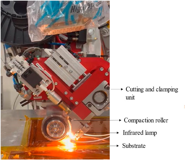
Figure 1. IR-assisted AFP head during placement of CF/PC on the tool, comprising a cutting and clamping unit, compaction roller, and infrared lamp as the heat source.
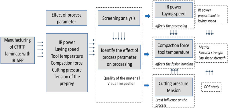
Figure 2. Flowchart illustrating the manufacturing process of CFRTP laminate with IR-AFP. It includes steps such as assessing the effect of process parameters like IR power, laying speed, tool temperature, compaction force, and tension. Screening analysis identifies their impact on processing quality. IR power and laying speed affect processing, while compaction force and tool temperature influence fusion bonding, with cutting pressure and tension having the least influence.
A structured DOE approach was adopted to evaluate the influence of compaction force and tool temperature on the mechanical properties of the manufactured laminates (Antony and Antony, 2014). Two levels were selected for each parameter, corresponding to their practical minimum and maximum operating ranges determined from preliminary trails and earlier studies. The DOE conditions were analyzed and optimized from the results of flexural and lap-shear strength. Four process conditions were selected based on the DOE as shown in the table. The details of the DOE condition with the input process parameters and the output responses are presented in Table 1. All other process parameters were kept constant during manufacturing based on the screening analysis and earlier studies. Five samples were manufactured under each condition for mechanical analysis. Further, based on the optimized process parameters, tensile samples and peel resistance samples were manufactured. Table 2 presents the list of samples for mechanical testing.
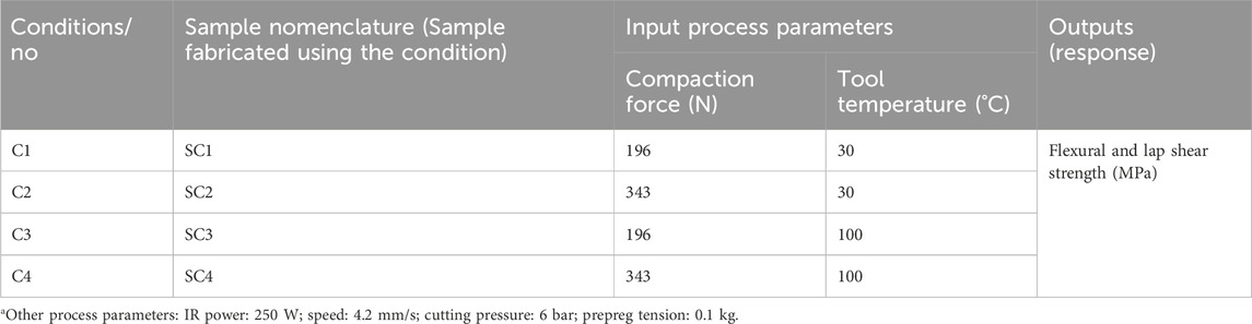
Table 1. Experimental layout of DOE process parameters and output responsea.
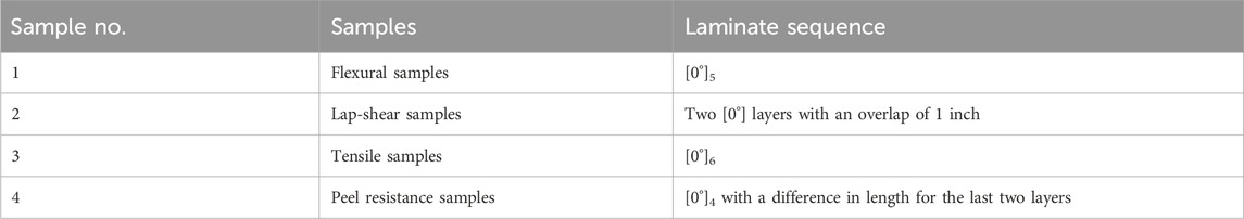
Table 2. Manufactured samples and their respective laminate sequences.
2.3 3D printing of curved mold using polyetherimide
Laying prepreg onto a 3D mold offers the advantage of fabricating a single, integrated structure with enhanced fusion between the prepreg and the mold surface. A cylindrical 3D model of the mold of 31 × 100 mm (diameter × height) was designed using SOLIDWORKS and was printed using a high temperature INSTAMYS- FUNMAT-HT 3D printer. To fully utilize the potential of AFP, a high temperature Polyetherimide (PEI) 9,085 polymer was selected for 3D printing of mold. Finite element analysis (FEA) was performed to validate the material selection in terms of strength, ensuring the mold can withstand the compaction force of 344.35 N exerted by the AFP head during manufacturing process.
For the FEA static analysis, the model is first assigned the material properties of the INTAMSYS Ultem 9085 PEI filament as per INTAMSYS data sheet, having tensile strength of 85 MPa and Elastic Modulus of 2,230 MPa. As for the boundary conditions, a fixed geometry fixture is applied onto the internal surface of the mold, and a distributed normal force of 343.35 N is applied onto the external surface of the mold. As for the mesh information details, they are presented in Table 3. A refinement study (2.3 mm element size) confirmed mesh independence, with less than 3% variation in maximum von mises stress compared to the baseline mesh.

Table 3. Details on the meshing.
Based on the FEA results, the maximum Von Mises stress that is applied onto the mold is 0.043 MPa, which is within the material Ultimate Tensile Strength of 85.0 MPa. Also, the maximum displacement observed is 0.1048 µm, which can be considered as negligible. The tool path for prepreg placement on the curved surface was generated using the HAL plugin Rhino (Figure 3). The sequential process for curved-surface layup is illustrated in Figure 4, and the key 3D printing parameters for the PEI mold are summarized in Table 4.
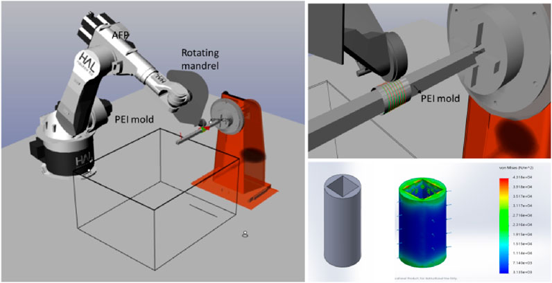
Figure 3. Representation of HAL simulation of an AFP robot placing prepreg on a rotating mandrel with a cylindrical PEI mold. On the right is a close-up of the process, and below is a cylindrical model depicting stress analysis with a color scale from red to blue indicating von Mises stress levels.
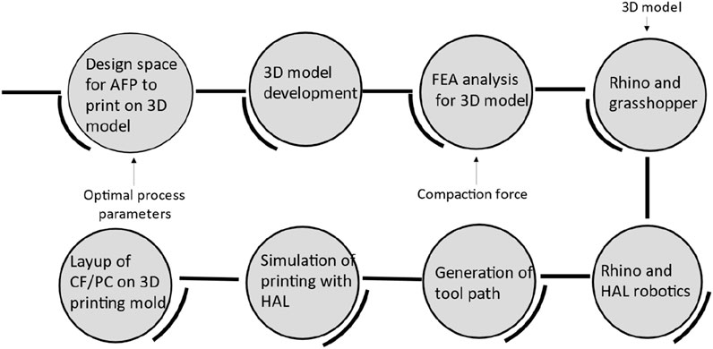
Figure 4. Flowchart diagram showing seven stages for the placement of CF/PC on a 3D printed PEI mold. The stages include design space, 3D model development, FEA analysis, Rhino and Grasshopper, layup on the mold, simulation with HAL, and toolpath generation. Arrows indicate the process flow and interactions.

Table 4. 3D printing parameters for PEI mold.
2.4 Thermal analysis of IR lamp
The temperature of the IR lamp during the fabrication process was monitored using a high-temperature thermistor (RS Components, Singapore) and an Arduino Uno microcontroller board. The thermistor was connected to the Arduino board with a 1,000 Ω resistor connected in series (Figure 5ii). The Arduino board was controlled by the Arduino IDE programming platform to measure the input signal (voltage) and convert it into temperature (°C) every 500 ms. The temperature of the IR lamp was thus recorded and analyzed. The flow chart of the monitoring process and the position of the thermistor and Arduino is shown in Figure 5.
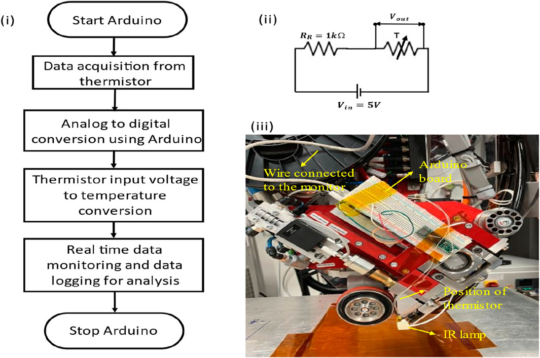
Figure 5. Microcontroller-assisted thermal analysis of the IR lamp during processing: (i) flowchart of the thermal analysis using a thermistor and Arduino; (ii) circuit diagram with a resistor and thermistor for measuring voltage; and (iii) position of the thermistor in the AFP head, including a wire to the monitor, an Arduino board, a thermistor, and an IR lamp.
2.5 Mechanical and microstructural analysis
The details of the mechanical test are summarized below Table 5. Five samples for each condition were fabricated. A total of 40 samples were fabricated for bending and LSS tests to assess the effects of compaction force and tool temperature. The LSS test involves two unidirectional samples overlapped by 1 inch and tested at 13 mm/min using the Instron Universal testing machine. The load and deflection of the samples were analyzed and compared. The tensile and peel strength samples were fabricated using the optimized compaction force and tool temperature. The tensile test was performed on [0°]6 laminated using a 100 kN load cell at the rate of 1 mm/s.
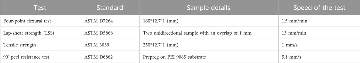
Table 5. Mechanical testing details.
The peel-resistant strength of the CF/PC material fabricated using IR-assisted AFP was analyzed to understand the uniformity in bonding between layers. The interfacial bond strength between two prepreg layers was determined by a 90° peel test. The peel test fixture was placed in an MTS universal testing machine with a load cell of 10 kN. A grip enabled the top prepreg to be peeled apart gently from the substrate. The test was conducted by using a standard 90° peel test fixture with a sliding table placed in the universal testing machine. The samples were prepared on a 3D printed PEI-9085 substrate to position the sample on the sliding table, and the prepreg was laid on it at two different lengths as prescribed in the ASTM D6862 standard. The top layer was clamped firmly with the upper grips and pulled with the tensile force from the bottom layer at a crosshead speed of 5.1 mm/s. The data was recorded and analyzed. The tested samples were first examined through visual inspection to assess overall laminate quality, followed by detailed microstructural characterization using 3D digital microscopy (HIROX, EUROPE) and optical microscopy.
3 Results and discussion
3.1 Compaction roller material
In a multi-physics system like AFP, the selection of compaction roller material plays a critical role in process stability due to its influence on heat transfer and pressure distribution. To evaluate the processability of CF/PC prepreg, preliminary trials were conducted using two roller types (i) steel and (ii) silicone. A few layers of prepreg were laid with each roller to assess their influence on part quality. A steel compaction roller produces pronounced defects such as tow folding and wrinkling in the layers. During deposition of the second layer on top of the first, non-stickiness and warpage of the top layer were observed. These defects were consistent in all the samples fabricated using the steel compaction roller, regardless of the process parameters. The silicone compaction roller produced better samples without any visible defects. This difference could be explained by the rigidity and thermal properties of the steel roller. While a detailed investigation of this defect mechanism is outside the scope of this study, the silicone compaction roller demonstrated superior performance and was therefore selected for all subsequent CF/PC fabrication. Representative images of the defects induced by the steel roller are shown in Figure 6i, ii with microscopic evidence of prepreg folding presented in Figure 6iii.
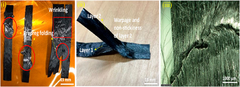
Figure 6. Pictures of the manufacturing defect caused by the steel compaction roller; (i) wrinkles and folding of the prepreg observed in the samples; (ii) warpage and non-stickiness of the second layer (prepreg); and (iii) micrograph of the prepreg folding observed using digital microscopy.
3.2 Thermal analysis of IR lamp
IR-assisted AFP offers cost-effectiveness and lower safety risks compared to other heating methods; however, its rapid heating and cooling rates can cause non-uniform heat distribution, affecting material processability. To address this, a low-cost micro controller-based temperature monitoring system was developed, using a thermistor with data acquisition via the Arduino IDE. for the IR lamp. The heat source had three points of ON/OFF during the fabrication process. First, the heat source was ON at the starting point of the tow, then it stopped and restarted (in 2 s) at the cut position, and finally, it was OFF at the end position. The robot moved from the end position of the first tow to the start position of the second tow while the heat source remained OFF to avoid reheating the sample. The ramping of temperature during these positions was studied to obtain the temperature profile of the heat source. The thermal profiling was performed at 250 W and 4.2 mm/s for a 250 mm long prepreg tow. The lamp exhibited heating and cooling rates of ∼3.5 °C/s, with an initial rapid rise of ∼65 °C/s followed by ∼35 °C/s. No significant temperature drop was observed at the cut position, indicating non-uniform irradiation. Figure 7 presents the thermal profile, which will be integrated into a feedback-controlled PLC system for real-time regulation. Continuous monitoring can provide hints about the degradation of the lamp through the usage cycle.
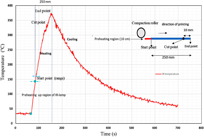
Figure 7. Graphical representation of the temperature profile of the IR lamp based on the thermistor reading on the IR lamp showing the stages of irradiation (heating) and cooling of the IR lamp during the printing of the 250-mm-long prepreg tow.
3.3 Mechanical testing
In this section, the results from the mechanical tests performed on CF/PC materials are presented. Initially, the flexural and LSS test results are performed to optimize the process settings based on the DOE conditions. Overall, the sample fabricated under condition 4 (100 °C/343 N) shows high flexural and lap-shear strengths. Thus, using condition 4, tensile and peel-resistance strength samples were fabricated and tested. The individual tests and results are discussed below.
3.3.1 Four-point bending test
The flexural strength was analyzed and compared for the samples manufactured under four DOE conditions. The flexural strengths calculated for each condition were compared, and the highest flexural strength of 521 MPa was obtained for SC4, whereas the lowest flexural strength was observed for SC2. The value of the highest flexural strength was considered to be 100%, and the percentage decreases in flexural strength obtained for the other samples are summarized in Table 6.
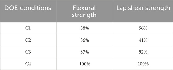
Table 6. Calculated flexural and lap-shear strengths as percentages for each DOE condition.
Significant differences in the flexural strength and failure behaviors were observed in the samples. For SC1 and SC2, the compaction force was increased, whereas the tool temperature was maintained at 30 °C, and little or no difference in flexural strength is observed. In contrast, increasing the compaction force and the tool temperature to 100 °C increases the flexural strength efficiently (for SC3 and SC4). Comparing the samples fabricated with C1 and C3, increasing the tool temperature with a constant compaction force results in an increase of approximately 31% in the flexural strength. Similarly, comparing the samples manufactured with C2 and C4, the flexural strength is increased by 44%. The results show that a higher tool temperature has a significant effect on flexural strength and is mandatory for manufacturing CF/PC samples. Overall, the samples manufactured under C4 exhibit the highest flexural strength among the samples. The compaction force exhibits a minimal impact on the flexural strength, whereas the tool temperature exhibits a high impact. The flexural strengths calculated under the four DOE conditions are shown in Figure 8. The fractography of the samples was observed using a microscope for each condition and are presented in Figure 9.
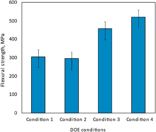
Figure 8. Bar chart displaying flexural strength in megapascals (MPa) for four DOE conditions. Condition 1 and 2 show similar strength around 300 MPa, Condition 3 is higher at approximately 400 MPa, and Condition 4 is the highest at about 500 MPa.
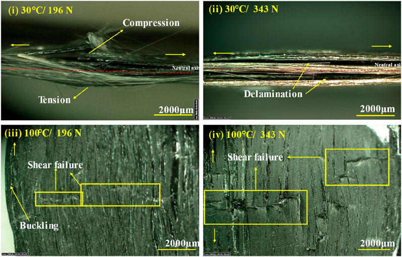
Figure 9. Micrographs of fracture surface predominantly observed in the samples viewed using digital microscopy; (i) C1: breakage of the sample; (ii) C2: delamination observed in the cross-section; (iii) C3: shear failure observed on the compression side; and (iv) C4: shear failure.
The samples fabricated under condition 1 exhibit complete delamination of the layers exactly at the region of bending (Figure 9i). Meanwhile, for SC2, the failure starts with buckling at the compression side, and then, combined with the delamination, failure results (Figure 9ii). The temperature difference between the tool and prepreg layer leads to poor fusion bonding, which ultimately results in delamination. For SC3, buckling initiates at the compression side and then propagates to the tension side. Finally, delamination of the sample outside the region of bending (Figure 9iii) and shear failure are observed. Minimum delamination is observed for the samples made under condition 4. The type of failure observed in these samples is shear failure on the compression side exactly at the region of bending (Figure 9iv). From this observation, the tool temperature improves the bonding at the interlayer, thus delamination is not predominant for SC3 and SC4. A similar material used in additive manufacturing serve was used as a benchmark for flexural analysis. The flexural strength of the additively manufactured sample is 13% higher than that of the AFP manufactured samples. Further analysis on improving the mechanical properties needs to be performed in future studies.
The samples manufactured under process condition 4 (tool temperature of 100 °C and compaction force of 343 N) were analyzed for cross-sectional micrographs. The samples were casted in epoxy in a vacuum chamber and then cut, ground, and polished. The longitudinal sections of the samples are shown in Figure 10. The microstructure of flexural samples with five layers are clearly visible. Few areas of fiber breakage are apparent, and the interphase is observed as resin-rich areas. The resin-rich areas confirm the interphase formation of the resin. There are no observed voids or delamination. The samples should be compared with a hot-press or autoclave samples for further comparison.
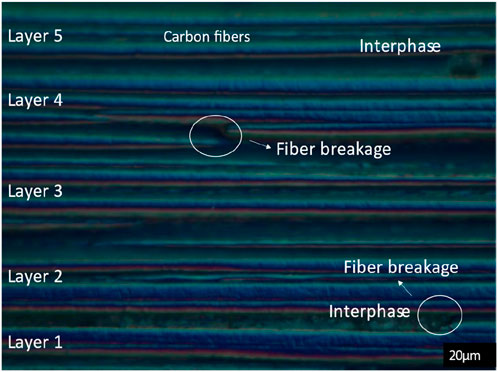
Figure 10. Micrographs of the longitudinal section at 500× of samples manufactured using condition 4.
3.3.2 Lap-shear strength analysis
Lap-shear strength is a representation of the bond strength of the CF/PC layers fused by the AFP process. The impact of process parameters on the lap-shear strength is similar to that observed in the flexural results. The lap-shear strength is the highest for the samples fabricated using condition 4 (i.e., 4.82 MPa). The impact of the tool temperature is higher than that of the compaction force. Nonetheless, the combined influence is difficult to analyze and explain. The samples made using condition 2 exhibit the lowest lap-shear strength of 2.20 MPa. A schematic representation of the calculated lap-shear strength values is shown in Figure 11. Rather than the lap-shear strength, the failure behavior of the samples gives interesting insight into the overlap region.
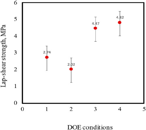
Figure 11. Lap shear strength for each DOE condition.
The morphology of the sample failure was observed using digital microscopy. The samples fabricated with conditions 1 and 2 exhibit failure exactly at the overlap region, which shows that the bonding strength is lower than the pulling strength. This finding is in line with the flexural strength analysis results. The samples fabricated with C1 show adhesion failure, where the layer is completely peeled off from the other layer with minimum fiber breakage at the edges, as shown in Figure 12i. The samples fabricated with C2 exhibit a mixed mode of failure, cohesion, and adhesion with fragments of the peeled layers and minimum tearing of the prepreg, as depicted in Figure 12ii. Increasing the compaction force with a lower tool temperature will not improve the fusion bonding.
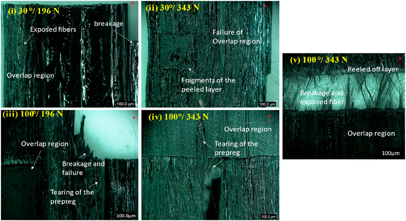
Figure 12. Micrographs of the failure behaviour observed using digital microscopy for samples manufactured under (i) C1: exhibits the complete failure of the overlap region, (ii) C2: mixed mode of failure with fragments of the peeled layers, (iii) C3: partial failure and tearing in the overlap region, and (iv) and (v) C4: tearing and fiber breakage in the overlap region.
The failure for the samples fabricated with C3 starts with tearing in the lateral direction and partial failure of the overlap region with fiber bursting either at the start of the overlap or in the overlap region (Figure 12iii). Surprisingly, the overlap region did not fail for the sample fabricated using condition 4. Bursting of fibers before the overlap region or a small percentage of tearing in the lateral direction is observed. Figures 12iv,v show the failure of the LSS samples fabricated with condition 4. The results demonstrate that the bond strengths of the samples manufactured under condition 4 are higher than those produced under the other conditions, which agrees with the results of previous studies on CF/PA 6.
3.3.3 Tensile analysis and peel test
Figure 13i shows typical load-displacement curves of the unidirectional CF/PC samples fabricated with optimized process settings (condition 4). The tensile stress and strain were calculated from the recorded load-displacement curve. The ultimate tensile strength (UTS) was determined from the maximum load, and the tensile modulus was calculated in the elastic region of the graph (Figure 13ii). Overall, the tensile behavior of CF/PC was observed with a UTS of 872 MPa and Young’s modulus of 53 GPa with a minimum standard deviation. The material exhibits a linear stress-strain relation, and the failure mode is observed to be brittle with fiber pullout. The load-carrying capacity of the sample drops drastically at the ultimate tensile strength, and the sample fails with minimum or no further elongation. The initial failure was fiber breakage, followed by a catastrophic failure of the sample with fiber pullout with dispersion. The micrographs of the samples reveal regions of longitudinal splitting, debonding, and dispersed fiber, as shown in Figure 14. The tensile strength, stress-strain relation, and Young’s modulus of the CF/PC fabricated with IR-assisted AFP are given through this test. The samples can be compared with hot-press or autoclave samples to understand the decrease in strength with respect to the type of fabrication process.
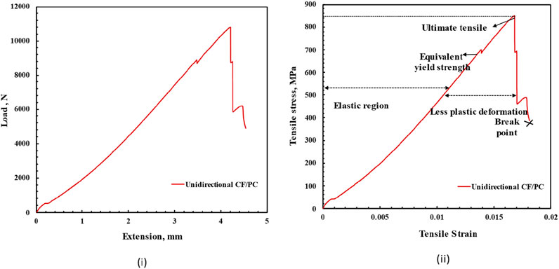
Figure 13. Representative tensile graphs of unidirectional CF/PC samples: (i) load versus extension curve and (ii) stress versus strain curve with the UTS and fracture point.
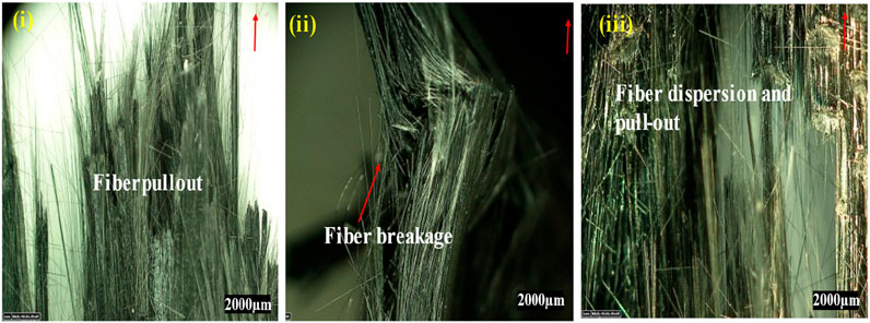
Figure 14. Micrographs of tensile fracture samples: (i) dispersed fibers; (ii) fracture observed from the cross-section; and (iii) fiber bursting and dispersion observed by digital micrography (red curve shows the direction of pulling).
3.3.4 90° peel resistance strength analysis
The 90-degree peel test was conducted to determine the resistance-to-peel strength at the interface of two prepreg fabricated using IR-assisted AFP. Usually, peel tests are performed to characterize the adhesion between soft (flexible) and hard materials; the soft material needs to be pulled at approximately 90°. For this test, the first layer of the prepreg was formed in a way that it warped and could be pulled at approximately 90° (Figure 15i). The test measured the force required to remove the first layer from the second layer, which was bonded using AFP. The purposefully unbonded end of the top prepreg was bent perpendicular to the bottom prepreg and clamped into the grips (at an angle of ∼90°). The grip allowed the top layer to be peeled apart gently from the substrate. The test ended when the complete peeling of the top prepreg was observed. The test was repeated for five samples. The average and maximum peel forces were calculated from the obtained autographic curve, as shown in Figure 15iii.
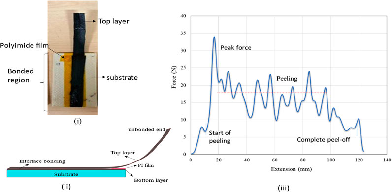
Figure 15. (i) Picture of 90° peel test samples of CF/PC manufactured on PEI substrate; (ii) schematic representation of the peel test samples with the separating PI film; and (iii) representative autographic curve obtained from the peel-resistant strength analysis.
The data revealed that the force changes throughout the length of the sample. The force to peel the layer varies with the lay-up length, which shows that further improvement in the fusion bonding is needed. Fluctuations were also observed due to the small movements of the substrate layer. During the test, the interface was found to have small areas of non-stickiness and areas of strong adhesion than the other areas. The maximum and minimum peaks explain the range variations in the bonding and higher consolidated regions. The microstructural studies revealed the areas of strong adhesion where fiber breakage was observed. Unexpectedly, there were large standard deviations, which need to be analyzed further. The average and maximum load to separate the prepregs were 25 N and 35 N, respectively. The average resistant-to-peel strength calculated from the analysis was 1.95 kN/m, and the maximum resistance to peel strength of the interface was 2.5 kN/m. The samples were observed under a microscope to check the uniformity of the failure mode during peeling. The failure mode was observed to be a mix of cohesive and adhesive modes. In certain regions, breakage of the failure was visible, due to either the angle of pulling or higher bond strength. The micrograph in Figure 16 shows the exposed fibers, regions of fiber breakage, and unaffected regions.
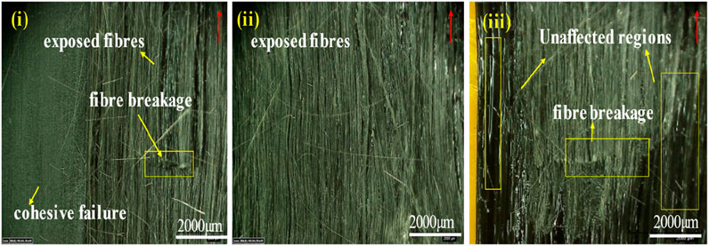
Figure 16. Micrographs of peel test failed samples of CF/PC observed using digital microscopy: (i) combined failure with fiber breakage and exposed fibers due to pulling; (ii) exposed fiber and matrix failure; and (iii) unaffected regions (red arrow show the direction of peeling.
3.4 In-situ fabrication of CF/PC laminate
Using the optimized process condition, a flat laminate of (500*500*1) mm was fabricated. This is the first study to demonstrate the potential of IR-assisted AFP for the fabrication of a flat CF/PC laminate with a laminate sequence of [0/90/0]2 (Figure 17). Each layer of the laminate consists of 39 prepreg tows, with a total of six layers. This sample was manufactured to prove the efficiency of IR-assisted AFP in manufacturing CF/PC with better mechanical properties and quality. During the fabrication, no time was spent on manual correction, and the fabrication was seamless. The fabrication shows the processability of CF/PC with IR-assisted AFP. This result is significant because AFP fabrication requires manual inspection and reworking multiple times, which extends the process by 2.5 times (Rudberg et al., 2014). This study demonstrates the reliability and productivity of the process. The fabricated laminates were observed with minimum warpage and no distortions, although a few spots of visible gaps occurred at random places. The gaps were observed at the edges (Figure 18i) and near the edge in both directions (Figure 18ii). The gaps seem to be due to the steering defects, and they will affect the structural performance (Blom et al., 2009), which is beyond the scope of this study.
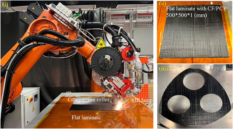
Figure 17. Pictures of (i) IR-assisted AFP during the processing of CF/PC flat laminate; (ii) flat laminate with a length, width, and thickness of 500 mm, 500 mm, and 1 mm, respectively, and a lay-up orientation of [0/90/0]2; and (iii) CF/PC laminated cut by waterjet for demonstration of a drone frame structure.
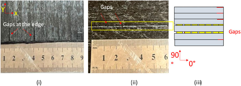
Figure 18. Pictures of defects observed in the flat laminate fabricated with CF/PC: (i) gaps observed at edges; (ii) gaps in the direction of the prepreg; and (iii) schematic representation of the gaps in the laminate.
Manufacturing a flat laminate is important to highlight the practical application of CF/PC manufactured with IR-assisted AFP. The flat laminate was fabricated for a potential application in building a drone frame for demonstration. The laminate was cut using waterjet cutting (speed of 1 mm/min), forming three holes to place the propeller. The demonstration of this application constitutes a subject of further study. In addition, the sample mechanical strength is being analyzed to investigate the effect of gaps in mechanical performance.
3.5 Fabrication of CF/PC on rotating 3D printed PEI cylindrical mold
This initial study was conducted to understand the fabrication process on a cylindrical 3D printed part. In this way, additive manufacturing technology and AFP were combined to create a structural part. This is an extended study to understand and implement the process knowledge of AFP to fabricate CF/PC on cylindrical 3D printed mold. The first step is to understand the compatibility of CF/PC with PEI mold. Followed by the effectiveness of the generated tool-path strategy to print without collision and minimum defects (Figure 19). This demonstrated the printing of CFRTP on 3D printed PEI mold in smaller scale. The major challenges such as insufficient adhesion between the mold and CF/PC and overlapping of the layers were observed. Further, heating of the rotating surface, controlling the prepreg tension, and complexity in the tool path were also observed. Further investigation of the improvements to achieve better laminate quality is ongoing.
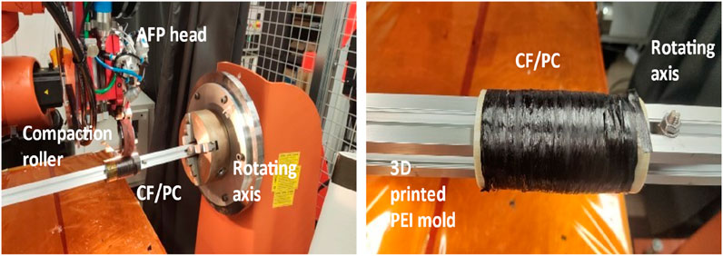
Figure 19. AFP setup showing the placement of CF/PC on a PEI mold placed in the rotating mandrel and on the right, picture showing CF/PC layers placed on the PEI mold with distortions.
4 Conclusion
In this study, CF/PC composite laminate samples processed using IR-assisted AFP were evaluated for the first time, and an optimal process window was obtained. The study analyzed the flexural, tensile, lap shear, and peel-resistance strength of the CF/PC samples. This research provides detailed knowledge of the processing and mechanical performance of CF/PC samples manufactured with IR-assisted AFP. Moreover, it demonstrates the manufacturing of a flat laminate with IR-assisted AFP and printing on a 3D printed mold placed on a rotating mandrel. This investigation constitutes a baseline study of CF/PC and will provide significant insight for subsequent research in the manufacturing of CF/PC with AFP. Based on the set of experimental investigations conducted in this study, the following conclusions could be drawn.
• For the manufacturing of CF/PC samples with IR-assisted AFP, a steel compaction roller has a negative impact and should be avoided. A silicone compaction roller provides better results and should be used to improve consolidation.
• High flexural and lap-shear strengths of CF/PC were achieved for the samples manufactured using condition 4 with a tool temperature of 100 °C and compaction force of 343 N.
• The combined effect of the process conditions was investigated, and the optimal compaction force and tool temperature were 343 N and 100 °C, respectively, for manufacturing CF/PC samples with IR-assisted AFP. The tool temperature has stronger effects on the mechanical properties than the compaction force.
• With optimal process settings, the ultimate tensile strength and modulus of unidirectional CF/PC samples were evaluated and found to be 831 MPa. A simple and cost-effective method of analyzing IR power was discussed.
• The peel test is a quality indicator of the interface adhesion. The peel resistance strength of CF/PC was analyzed based on the 90° peel resistance test, and the average resistant-to-peel strength was 1.95 kN/m.
Further work includes the investigation of the void and thermal residual stress caused by process parameters. This study found the optimal process parameter to enhance the mechanical properties. Further research needs to be carried out to determine the dependence of the mechanical performance on the presence of gaps in the laminates. A machine learning approach to control the IR-lamp based on the thermistor reading is ongoing work for future studies.
Data availability statement
The original contributions presented in the study are included in the article/supplementary material, further inquiries can be directed to the corresponding author.
Author contributions
CV: Methodology, Validation, Conceptualization, Investigation, Writing – original draft, Writing – review and editing. MR: Writing – review and editing, Formal Analysis. FZ: Project administration, Writing – review and editing, Resources. UG: Writing – review and editing, Data curation. AS: Writing – review and editing, Funding acquisition, Project administration, Resources.
Funding
The author(s) declare that financial support was received for the research and/or publication of this article. This project was supported by the Agency for Science, Technology and Research (A*STAR), Singapore, under the project code A19C9a0044 and the title “Polymer Matrix Composites Project.”
Conflict of interest
The authors declare that the research was conducted in the absence of any commercial or financial relationships that could be construed as a potential conflict of interest.
Generative AI statement
The author(s) declare that no Generative AI was used in the creation of this manuscript.
Any alternative text (alt text) provided alongside figures in this article has been generated by Frontiers with the support of artificial intelligence and reasonable efforts have been made to ensure accuracy, including review by the authors wherever possible. If you identify any issues, please contact us.
Publisher’s note
All claims expressed in this article are solely those of the authors and do not necessarily represent those of their affiliated organizations, or those of the publisher, the editors and the reviewers. Any product that may be evaluated in this article, or claim that may be made by its manufacturer, is not guaranteed or endorsed by the publisher.
References
Antony, J. (2014). 6 - full factorial designs. In: Antony J., editor. Design of experiments for engineers and scientists. Oxford: Elsevier. Second Edition. p. 63–85.
Bannister, M. (2001). Challenges for composites into the next millennium—a reinforcement perspective. Compos Part Appl. Sci. Manuf. 32 (7), 901–910. doi:10.1016/s1359-835x(01)00008-2
Blom, A. W., Lopes, C. S., Kromwijk, P. J., Gurdal, Z., and Camanho, P. P. (2009). A theoretical model to study the influence of tow-drop areas on the stiffness and strength of variable-stiffness laminates. J. Compos Mater 43 (5), 403–425. doi:10.1177/0021998308097675
Brzeski, M., Holschuh, R., and Schledjewski, R. (2010). Effect of tool temperature on laminate properties during in situ consolidation placement process. In: Proceedings of the 55th international SAMPE conference and exhibition; Seattle.
Chen, J., Chen-Keat, T., Hojjati, M., Vallee, A. J., Octeau, M. A., and Yousefpour, A. (2015). Impact of layup rate on the quality of fiber steering/cut-restart in automated fiber placement processes. Sci. Eng. Compos Mater 22 (2), 165–173. doi:10.1515/secm-2013-0257
Chen, J., Fu, K., and Li, Y. (2121). Understanding processing parameter effects for carbon fibre reinforced thermoplastic composites manufactured by laser-assisted automated fibre placement (AFP). Compos Part Appl. Sci. Manuf. 140, 106160. doi:10.1016/j.compositesa.2020.106160
Clancy, G., Peeters, D., Oliveri, V., Jones, D., O'Higgins, R. M., and Weaver, P. M. (2019). A study of the influence of processing parameters on steering of carbon fibre/PEEK tapes using laser-assisted tape placement. Compos Part B Eng. 163, 243–251. doi:10.1016/j.compositesb.2018.11.033
Comer, A. J., Ray, D., Obande, W. O., Jones, D., Lyons, J., Rosca, I., et al. (2015). Mechanical characterisation of carbon fibre–PEEK manufactured by laser-assisted automated-tape-placement and autoclave. Compos Part Appl. Sci. Manuf. 69, 10–20. doi:10.1016/j.compositesa.2014.10.003
Croft, K., Lessard, L., Pasini, D., Hojjati, M., Chen, J., and Yousefpour, A. (2001). Experimental study of the effect of automated fiber placement induced defects on performance of composite laminates. Compos Part Appl. Sci. Manuf. 42 (5), 484–491. doi:10.1016/j.compositesa.2011.01.007
Di Francesco, M., Valverde, M. A., Ward, C., Giddings, P. F., Dell’Anno, G., and Potter, K. (2016). Influence of layup speed on the quality of thermoplastic preforms manufactured by laser-assisted automated fibre placement. In: Proceedings of the 17th European conference on composite materials; 2016 June 26-30; Munich, Germany.
Gardner Business Media (2019). Thermoplastic composites: poised to step forward. Cincinnati, OH: Gardner Business Media. Available online at: https://www.compositesworld.com/articles/thermoplastic-composites-poised-to-step-forward (Accessed May 31, 2022).
Grouve, W. J. B., Warnet, L. L., Rietman, B., Visser, H. A., and Akkerman, R. (2013). Optimization of the tape placement process parameters for carbon–PPS composites. Compos Part Appl. Sci. Manuf. 50, 44–53. doi:10.1016/j.compositesa.2013.03.003
Jensen, B. J., Kinney, M. C., Cano, R. J., and Grimsley, B. W. (2012). Materials for heated head automated thermoplastic tape placement. In: Proceeding of SAMPE conference; 2024 May 20–23; Baltimore.
Kessler, S. S., Spearing, S. M., and Soutis, C. (2002). Damage detection in composite materials using Lamb wave methods. Smart Mater Struct. 11 (2), 269–278. doi:10.1088/0964-1726/11/2/310
Khan, M. A., Mitschang, P., and Schledjewski, R. (2010). Identification of some optimal parameters to achieve higher laminate quality through tape placement process. Adv. Polym. Technol. 29 (2), 98–111. doi:10.1002/adv.20177
Marsh, G. (2011). Automating aerospace composites production with fibre placement. Reinf. Plast. 55 (3), 32–37. doi:10.1016/s0034-3617(11)70075-3
Pistor, C. M., Yardimci, M. A., and Güçeri, S. I. (1999). On-line consolidation of thermoplastic composites using laser scanning. Compos Part Appl. Sci. Manuf. 30 (10), 1149–1157. doi:10.1016/S1359-835X(99)00030-5
Pitchumani, R., Gillespie, Jr J. W., and Lamontia, M. A. (1997). Design and optimization of a thermoplastic tow-placement process with in-situ consolidation. J. Compos Mater 31 (3), 244–275. doi:10.1177/002199839703100302
Rudberg, T., Nielson, J., Henscheid, M., and Cemenska, J. (2014). Improving AFP cell performance. SAE Int. J. Aerosp. 7 (2), 317–321. doi:10.4271/2014-01-2272
Saenz-Castillo, D., Martín, M. I., Calvo, S., Rodriguez-Lence, F., and Güemes, A. (2019). Effect of processing parameters and void content on mechanical properties and NDI of thermoplastic composites. Compos Part Appl. Sci. Manuf. 121, 308–320. doi:10.1016/j.compositesa.2019.03.035
Sawicki, A., and Minguett, P. (1998). The effect of intraply overlaps and gaps upon the compression strength of composite laminates. In: 39th AIAA/ASME/ASCE/AHS/ASC structures, structural dynamics, and materials conference and exhibit; 1998 April 20–23; Long Beach,CA. p. 744–754.
Schell, J. S. U., Guilleminot, J., Binetruy, C., and Krawczak, P. (2009). Computational and experimental analysis of fusion bonding in thermoplastic composites: influence of process parameters. J. Mater Process Technol. 209 (11), 5211–5219. doi:10.1016/j.jmatprotec.2009.03.008
Schiel, I., Raps, L., Chadwick, A. R., Schmidt, I., Simone, M., and Nowotny, S. (2020). An investigation of in-situ AFP process parameters using CF/LM-PAEK. Adv. Manuf. Polym. Compos Sci. 6 (4), 191–197. doi:10.1080/20550340.2020.1826772
Sonmez, F. O., and Akbulut, M. (2007). Process optimization of tape placement for thermoplastic composites. Compos Part Appl. Sci. Manuf. 38 (9), 2013–2023. doi:10.1016/j.compositesa.2007.05.003
Stanley, W. F., and Mallon, P. J. (2006). Intraply shear characterisation of a fibre reinforced thermoplastic composite. Compos Part Appl. Sci. Manuf. 37 (6), 939–948. doi:10.1016/j.compositesa.2005.03.017
Stokes-Griffin, C. M., and Compston, P. (2015). The effect of processing temperature and placement rate on the short beam strength of carbon fibre–PEEK manufactured using a laser tape placement process. Compos Part Appl. Sci. Manuf. 78, 274–283. doi:10.1016/j.compositesa.2015.08.008
Stokes-Griffin, C. M., Kollmannsberger, A., Ehard, S., Compston, P., and Drechsler, K. (2018). Manufacture of steel–CF/PA6 hybrids in a laser tape placement process: effect of first-ply placement rate on thermal history and lap shear strength. Compos Part Appl. Sci. Manuf. 111, 42–53. doi:10.1016/j.compositesa.2018.05.007
Stokes-Griffin, C. M., Kollmannsberger, A., Compston, P., and Drechsler, K. (2019). The effect of processing temperature on wedge peel strength of CF/PA6 laminates manufactured in a laser tape placement process. Compos Part Appl. Sci. Manuf. 121, 84–91. doi:10.1016/j.compositesa.2019.02.011
Tierney, J., and Gillespie, Jr J. W. (2006). Modeling of in situ strength development for the thermoplastic composite tow placement process. J. Compos Mater 40 (16), 1487–1506. doi:10.1177/0021998306060162
Venkatesan, C., Velu, R., Vaheed, N., Raspall, F., Tay, T. E., and Silva, A. (2020). Effect of process parameters on polyamide-6 carbon fibre prepreg laminated by IR-assisted automated fibre placement. Int. J. Adv. Manuf. Technol. 108 (4), 1275–1284. doi:10.1007/s00170-020-05230-z
Keywords: automated fiber placement, carbon fiber reinforced thermoplastics (CFRTP), Process optimization, process-structure-property relationship, mechanical properties
Citation: Venkatesan C, Ridhwan M, Zulkifli F, Gupta U and Silva A (2025) Enhanced manufacturing quality of thermoplastic composites through infrared-assisted automated fiber placement. Front. Manuf. Technol. 5:1649798. doi: 10.3389/fmtec.2025.1649798
Received: 19 June 2025; Accepted: 22 September 2025;
Published: 15 October 2025.
Edited by:
Seemal Asif, Cranfield School of Engineering, United KingdomReviewed by:
Jinoop Arackal Narayanan, Teesside University, United KingdomYaru Zhang, Xi’an Jiaotong University, China
Copyright © 2025 Venkatesan, Ridhwan, Zulkifli, Gupta and Silva. This is an open-access article distributed under the terms of the Creative Commons Attribution License (CC BY). The use, distribution or reproduction in other forums is permitted, provided the original author(s) and the copyright owner(s) are credited and that the original publication in this journal is cited, in accordance with accepted academic practice. No use, distribution or reproduction is permitted which does not comply with these terms.
*Correspondence: Chadurvedi Venkatesan, Y2hhZHVydmVkaXNhaGk5MkBnbWFpbC5jb20=