 Prakash Chandra Mishra
- Department of Mechanical Engineering, Veer Surendra Sai University of Technology, Burla, India
This work is devoted to develop a transient thermo elastohydrodynamic model for thermal analysis of micro scale oil film with in piston compression ring-liner conjunction. In this paper, heat dissipation through piston to cylinder wall mainly considered via thin film of lubricant on convection and conduction mode. It also includes frictional heat generated due to ring liner co-action while balancing total heat of the engine system. Results presented in this paper show that frictional heating raises additional lubricant temperature of 90°C. Such increase in temperature is one of the reasons for presence of further oil degradation in high pressure zone of engine cycle, which appears between 300 and 400° crank location.
Introduction
The internal combustion engine is a thermodynamic system, which is operated in elevated temperature of about 100–500°C. Thermo mechanical failure like scuffing, wear out, thermal fatigue etc. are obvious due to the continuous combustion and heat dissipation followed by contact friction due to relative moving parts of a running engine. It is therefore essential to model the thermal behavior of moving component like piston compression ring and cylinder liner lubricated contact, which is considered to be the most friction contributing pair in a running engine. It can help predicting the life of lubricant and components more accurately.
In the recent years, many attempts are made to simulate piston-ring and cylinder liner with various numerical and analytical methods. Almost in every case, this contact problem is solved for friction and other performance parameters. It is done so by considering the ring-liner lubricated contact as hydrodynamic or elastohydrodynamic type conjunction that accommodates globally deformed ring shape. In some cases, the axial as well as lateral tilt motion of piston skirt and its effect on twisted ring and liner lubrication are addressed. Through years, researchers have been trying to understand the starved lubrication model (Finol et al., 2009), effect of distorted bore on lubrication (Mishra, 2013), cylinder bore distortion in running engine (Ma et al., 1995), and friction and wear behavior in piston ring and cylinder liner (PRCL) contact. The effect of liner roughness on friction characteristics was studied using deterministic as well as average flow model. In a rough liner, the cross hatched pattern of its surface has significant effect on lubricant flow and retention. Further, there are few experimental techniques developed to validate the numerical findings of such heat tribodynamic system. Piston ring and cylinder liner contact exhibit lubrication regime transition. That means, though there is hydrodynamic regime (h > 1.0 μm) in most part of engine cycle, because of elevated combustion gas pressure (between 300 and 400° crank location) in compression and power stroke transition, the most part of friction is lost in this region due to mixed regime. As discussed earlier, the engine being a thermo mechanical system develops temperature, which is sufficient enough to alter its rheological properties (viscosity, density, and hydrodynamic pressure) of associated lubricated contact pairs.
Current research deals with a transient thermoealstohydrodynamics model to study the thermal behaviors of micro order thin film of lubricant between piston ring and cylinder liner conjunction of a single cylinder methanol fuelled four stroke engines. The details of engine specification are given Supplementary Material. As Lubricants are synthesized taking into consideration of their temperature stability in maximum gross temperature of a hot engine (Finol et al., 2009). Again, heat rise due to friction is a transient phenomena and is highly variable. It depends on various factors like, engine speed, torque, fictional loss, duration of operation, lubricant rheology, piston subsystem dynamics etc. (Mishra, 2013).
The friction arise in this situation is sometimes due to fluid friction only when hydrodynamic condition prevails (2 μm < h < 5 μm) (Ma et al., 1996). At high combustion pressure in between crank location (300–400°) mixed regime appears (Mishra, 2012). Again, at reversal of TDC and BDC boundary regime and asperity contact occurs due to momentary cessation and piston sliding direction reversal (Mishra et al., 2008).
For this reason, temperature profile is developed due to convective heat transfer in hydrodynamic regime and mostly conductive heat transfer in mixed and boundary regime. This temperature alters the lubricant rheology (Shimada et al., 2004). Therefore, it is necessary to study temperature in various operating conditions.
Heat transfer from combustion chamber to the outer surface of the cylinder is a highly non-linear phenomenon (Finol et al., 2009). It passes directly or indirectly to the cylinder wall from the hot combustion chamber containing the combustion product of air fuel mixture. Direct heat transfer includes the radiation as well as conductive heat which are initiated from the time dependent variable combustion chamber. But the indirect heat transfer includes flow of heat first to moving piston assembly and then to cylinder liner through oil film of ring-liner and skirt-liner contact (Finol et al., 2009). The indirect heat transfer and its mode depends on the regime that the contact experiences. For example, in hydrodynamic regime that persists in most part of the engine cycle of skirt-liner and ring-liner contact, the film thickness ranges from 2 to 10 μm. During 300–400° crank location of a four stroke engine, mixed regime prevails because of higher combustion pressure on the back of the ring, which is in action for sealing (Mishra et al., 2009). The thermal balance between the coolant and the combustion gases is needed with additional heat sources due to contact friction because of viscous shear as well as asperity interaction (Morris et al., 2013). Such frictional heat and its reason for generation and its effect on lubricant temperature profile to be studied in this research paper. The temperature rise in lubrication alters the rheological properties. Reducing friction can minimize the temperature rise. Hence it is necessary to understand the mechanism of friction in such lubricating contact.
Contact friction in lubricated conjuction develops due to shear of lubricant layer. The hydrodynamic or EHL action plays a role (Dowson et al., 1983). The EHL action is quantified in terms of film pressure. Such damping effect is a function of film thickness; entrain velocity, viscosity, and density (Harigaya et al., 2003). Friction reduction is realized by replacing smooth cylinder liner by rough cylinder liner with cross-h pattern surface roughness. It is possible to maintain a smooth top and deep valley in such roughness pattern, which is manufactured by double honing process. Contact surface benefitted from smooth top and deep valley due to cross-h pattern resulting less friction because of smooth top and easier wear debris collection because of deep valley (Spencer et al., 2011). For simulation, a cross h pattern surface is difficult to characterize through traditional parameters like, average, rms, Rq. As such characterization yields significant errors and completely modifies the surface profile. Hence a bearing area curve based roughness characterization is suitable. Therefore, Rk characterization through DIN is found more suitable. In the mixed lubrication regime, the hydrodynamic/EHL effect is estimated using average flow based Reynolds equation. Flow factors used are modified introducing Rk into them. Numerically estimated friction thus matches with the experimentally measured friction by Furuhama and Sasaki (1983).
Piston subsystem contact friction also influenced due to bore-out-of-roundness and conformance of the ring in the out-of-round bore (Ma et al., 1995). Conformability is the ability of the ring to sit on the bore without leaving any gap. It is the function of ring elastic pressure, gas pressure, ring-bore geometry, and bore order (Hill and Newman, 1984). Further, bore out-of-roundness is due to improper machining, thermo elastic distortion (Sun, 1991) because of the heat generated in combustion chamber.
Bore-out-of-round profile effect also modifies the film profile and alters tribological performance. Higher bore order encourages enhanced friction and significant wear. The gas blow-by at higher combustion pressure during compression and power stroke is also a possibility which reduces the power output of the engine (Rahmani et al., 2012). All conditions in a running engine such as dynamics, heat effect, contact etc. are interlinked to each other. Even the wear behavior is linked to the conjunction gap of ring and liner (Ma et al., 2006). Transient nature of axial, later and tilt motion of piston skirt not only reduces the chance of piston scuffing, but also helps in flexing the ring during simultaneous sealing and sliding motion (Balakrishnan and Rahnejat, 2005). The out-of-round bore shape is responsible for a non-uniform gap of conformed ring and is critical to gas blow by Abe and Suzuki (1995) and Okamoto and Sakai (2001). Although such contacts are mostly operated in hydrodynamic regime, the friction loss is more in mixed regime because of reduced film thickness due to elevated combustion gas pressure. Even if there is no asperity contact in mixed regime, the micro structural orientation of the surface modifies the film geometry and requires a model of average flow type Reynolds equation to address the contact issues (Patir and Cheng, 1978, 1979). There is chance of asperity contact in ring-bore contact, even though it is momentary and mostly in the vicinity of dead centers (TDC and BDC). Here, the sliding velocity ceases and the hydrodynamic action prevails because of squeeze. As the squeezing action is not sufficient, the asperity contact is obvious. In this situation, the force balance is between the asperity contact pressure and the sum of gas pressure and ring elastic pressure. This is otherwise known as boundary regime in which the contact friction largely depends on the asperity density and asperity tip radius (Greenwood and Tripp, 1970). In context of regime transition, there are many research reported (Hu et al., 1994) and the friction force and power loss thus computed are verified with test bench results engine (Akalin and Newaz, 2001a,b; Bolander et al., 2005). The deterministic roughness characterization and asperity tip assumption to circular shape with measured roughness value (Xu and Sadeghi, 1996) are also of use in solving EHL problems. In the recent advances, the elastohydrodynamic lubrication of piston ring (Oh et al., 1987), thermo mixed hydrodynamic technique (Shahmohamadi et al., 2013), analytical evaluation of fitted compression ring modal behavior (Baker et al., 2011) and experimental evaluation of piston assembly friction in motored and fired condition (Mufti and Priest, 2005) are developed to supplement ring research. In addition to this, correlation study of piston ring design and lubrication (Söderfjäll et al., 2017), piston ring condition monitoring on basis of combustion and thermal characteristics (Mohamed, 2018) found useful in ring analysis. The effect of piston ring coating (Peng and Huang, 2017), piston elastohydrodynamic lubrication (Asaulyak et al., 2016), ring texturing and cylinder bore non-circularity consideration (Usman and Park, 2017) in both numerical and experimental methods provide many useful information to enhance ring and liner life.
Even though there are many useful findings in recent and earlier research activities in piston ring and cylinder liner contact friction analysis, analyzing film temperature considering all this area together will be a step further and hence is the aim of this research work.
Problem Formulation and Governing Equation
As stated earlier, the durability of components and lubricant largely depends on the friction loss occurred in a running engine. Because of higher temperature rise, there develops the thermal fatigue stress that lead to failure of component. Also, the reduced viscosity enhances the contact friction due to reduction in hydrodynamic pressure.
Why Thermal Modeling of Piston Ring and Cylinder Liner Contact?
Before we proceed with a decision to define the thermal modeling of piston compression ring and cylinder liner conjunction, let us first explain the meaning of ring-liner conjunction of piston-cylinder system. Following a recent work (Mishra et al., 2009), conjunction in context of ring-liner contact is defined as the variable gap left for the lubricant to flow, after the sealing action is performed. It is formed because of the inherent design of the sealing system meant for stopping the high pressure gas produced due to combustion of air fuel mixture. In transition, the film between ring-liner conjunctions varies from 0.5 to 5.0 μm (Mishra et al., 2009) due to action of combustion gas pressure on the back of the ring along with the ring elastic pressure force. It leads to lubrication regime transition from hydrodynamic to boundary through mixed. The rate of heat transfer and the wear behavior change accordingly. In most part of the engine cycle, this conjunction run hydrodynamically leading to less wear and tear of liner or ring. But in high pressure zone of engine cycle, as the mixed regime prevails on the vicinity of the dead center, the momentary cessation occurs; there is metal to metal contact due to very thin film presence. The wear and tear is higher because of this condition, though there is significant amount of heat transfer occur due to ultra-thin film presence (Ma et al., 2006). The frictional heating in all these cases are significantly different to each other because of viscous, asperity and eyring shear vary greatly from case to case. Hence a thermal model including this variable frictional heating with engine heat transfer is required to understand the engine heat dissipation more clearly.
Conjunction Parameters Setting for Thermal Modeling
Thermal modeling is based on the concept of heat transfer and lubrication science related to piston ring and skirt in contact with cylinder liner (Balakrishnan and Rahnejat, 2005). To achieve this, the ring geometry, skirt profile, liner surface texture and ring-bore conformability details are necessary. The quantification of all of them for the model is essential.
Ring Geometry
Ring geometry is a governing parameter that decides the shape of the film thickness. The shape of the ring given in Figure 1 is approximated by a parabola, thus:
Here, delta is the offset ratio, which is the distance between tip of the ring to the chord of the curvature. A parabolic profile generated due to ring off set sets a single point minima and a perfect converging-diverging zone conducive for better hydrodynamic action for both direction of reciprocation (Mishra et al., 2009). The parameter “b” is the ring face width and is the apparent line of contact.
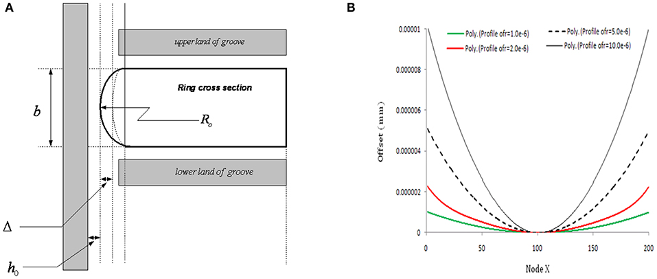
Figure 1. (A) Ring profile geometry. (B) Profile variation due to offset geometry.
Ring Bore Conformability
Conformability is the ability of the ring to fit to the bore inner circumference without leaving any gap (Abe and Suzuki, 1995). More conformed bore-ring arrangement has better sealing ability. As, the minimum film thickness is not uniform in circumferential direction due to bore-out-of-roundness present in cylinder liner. Hence ring is hardly fully conformed to the bore and suggests a conformability analysis to find the circumferentially variable ring liner gap. The Equation (1) shows the minimum ring-bore gap.
Where, .
And ξn(θc) is the conformability factor. It is a function of gas pressure force, ring elastic pressure force, ring geometry, and material strength. The bore is considered to be fourth order (n = 4).
The parameter “a” is the ring depth or the radial thickness of the ring. Net combustion gas pressure force acting on the ring is the difference of force from back and the front of the ring and is given as:
Where,
The elastic pressure around the ring circumference is not uniform (Okamoto and Sakai, 2001). It is maximum at point 90° from the free end. The maximum value is found to be 0.2 MPa. We have taken a uniform pressure of 0.2 MPa around the ring circumference.
The value of Fg is obtained from combustion gas pressure as per (Mishra, 2012). With such analysis, the non-axisymetric minimum gap along the ring circumference is estimated with inclusion of gas pressure. The mode shapes due to bore out-of-roundness is quantified through bore order. Various mode shapes and their deviation from nominal radius are given in Figure 2.
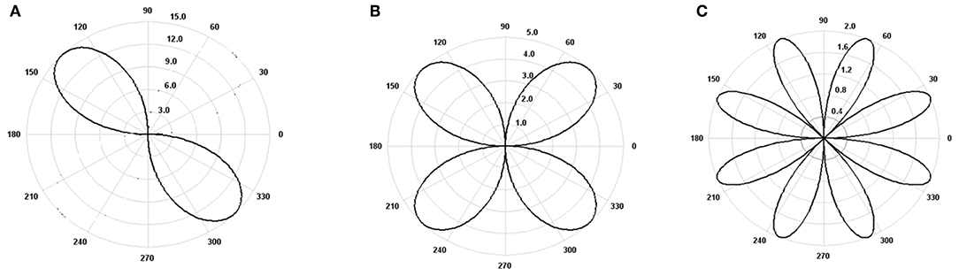
Figure 2. (A) Out-of-round second order bore, of 15 μm radial difference. (B) Out-of-round fourth order bore, of 5 μm radial difference. (C) Out-of-round eighth order bore, of 5 μm radial difference.
The bore is considered in this case to be oval after thermal and elastic distortion. Hence, it is assumed to be of fourth order bore. Surface roughness of smooth top and deep valley is intentionally created in liner surface for better lubrication. It is essential to understand the texture of the inner liner surface.
Skirt-Liner and Ring-Liner Conjunction Film Formulation at Mixed Regime
The film thickness between ring liner contact conjunction is the sum of nominal film, ring profile shape, the ring local deformation, and the ring global deformation. The order of film as reported (Mishra, 2012) is 0.5–5.0 μm. The gas pressure force and ring elastic pressure force have dominant effect on ring liner film.
While the film between skirt-liner is the sum of nominal film, skirt profile and skirt tilt due to relative eccentric positioning of top and bottom. The film is mostly governed by the inertia forces and moment produced during piston reciprocation (Balakrishnan and Rahnejat, 2005).
The order of skirt-liner film is of 5–20 μm and the regime of lubrication is always elostohydrodynamics. Most of the times when the friction loss is high and due to reduced film thickness of 1–3 μm, there happens the mixed regime of lubrication. It is the situation when there is no metal to metal contact, but the roughness profile affects greatly to the flow of lubricant in the conjuction. The condition best described through average flow Reynolds equation by Patir and Cheng, 1979) and is given in the Equation (8).
In Equation (8), ph is the hydrodynamic/EHL pressure developed in the lubricant film. The dimensional pressure from which ph is calculated is obtained by solving the average flow Reynolds equation (Patir and Cheng, 1978, 1979) given in Equation (8). The flow factors are the function of film parameter. As the roughness characterization changes, for same surface there is different value of flow factor. In this analysis such factors are derived based of Rk and is listed in the Appendix 1. The direction of oil entrainment is along x axis and that of side leakage is along y axis.
There exist the interdependency among the lubricant density, film pressure, temperature rise and the surrounding pressure as per (Houpert, 1985). It is given in Equation (9a). Again, the viscosity variation with variation of temperature and pressure is addressed using combined law (Dowson and Higginson, 1959; Mufti and Priest, 2005) given in Equation (9b) as.
Where: Θ = θ + 273 and Θ0 = θ0 + 273, and:
Shearing Action in Mixed Regime
The shear stress developed in mixed regime is due to rapid relative motion lubricant layer in the contiguous surface geometry (Patir and Cheng, 1979) affected conjunction and is given as:
Hence, the friction force is the integration of the shear stress over the contact area and is:
Boundary Friction for Piston Subsystem Contact
In boundary lubrication regime, the contact among asperities sustain load. This is originally addressed Greenwood and Tripp (1970); Ma et al. (1995); Akalin and Newaz (2001a,b); Bolander et al. (2005), and Mishra (2012), carried out and used a non-linear approximation applicable to piston ring and bore rough conjunction and predicted the pasp as:
In which, the surface roughness of ring and bore are assumed to be isotropic. The function F2.5(λrk) relates to the probability distribution of asperity heights. For a Gaussian distribution of asperities, F2.5(λrk) has the limiting form (Hu et al., 1994) as:
A curve-fit of this function is more suited to numerical analysis liner rough surface. For typical ring-bore contact Hu et al. (1994) state this function as:
Where: β = 4, A = 4.4068 ×10⁻⁵, z = 6.804, and (Stribeck's oil film parameter).
K* in Equation (17) is a function of the surface roughness as: .
In replacing Rk to the standard deviation of surface roughness the film ratio is upgraded to better and more realistic value. As the Rk parameter is right representation of roughness of cross-h pattern roughness embedded in the cylinder liner.
In the Equation (16), Fb is the friction force due to boundary lubrication. A thin adsorbed layer of lubricant resides on the asperity summit and exibit Non-Newtonian eyring shear stress. μ = 0.17 is the friction coefficient between the ring and the liner material. This analysis is only meant for the boundary interaction (Bolander et al., 2005). When there is mixed regime, the friction calculation method changes. Although there are many deterministic model reported in the recent literatures on rough surface lubricated contact, but the current research work is limited to quantification of surface through curve fitting methods.
Internal combustion engine is designed to develop higher gas pressure (in the range of 120 bars) in every engine cycle. Only then such pressure force can be converted to the inertial dynamics of the piston to reciprocate and turn it into desired torque of the crank shaft. It has been possible due to explosive burning of air-fuel mixture that produces enormous heat and pressure. The Figure 3 shows the cyclic combustion chamber pressure along with inter ring gas pressure in the crank angle range 180–540. The reason for taking this crank range is the chamber pressure build-up mostly in this zone. In rest crank location it tends to zero and has negligible effect on performance parameters. There are two inter ring gap in a three ring piston assembly. Due to leakages of the gas, there is inter ring gas pressure also present in the piston assembly.
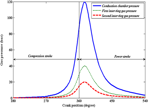
Figure 3. Combustion chamber pressure and inter ring gas pressure.
Thermal Heat Flux
The steady state distribution of convective and radiative heat fluxes over length of stroke at relevant location in cylinder bore. These heat fluxes are the results of heat directly transferred from working fluid to the wall of the cylinder. The steady state heat flux (Finol et al., 2009) as per Newton's law of cooling is given in Equation (17):
hg is the gas side heat transfer coefficient,
Tg is the gas temperature,
Twg is the surface temperature of the cylinder bore, and
qg heat flux rate.
Heat Conduction Through Piston Ring and Skirt to the Cylinder Liner
Heat transfer by conduction occurs between piston ring-cylinder wall and skirt-cylinder liner (Shahmohamadi et al., 2013). Assumption includes heat transfer from piston ring to lubricant oil and also from skirt to cylinder liner as per Fourier law of heat conduction in radial direction, which is given as:
The qpr is instantaneous heat flux between ring and the portion ring in contact with liner.
Similarly,
The qpsk is the instantaneous heat flux between skirt and the portion skirt in contact with liner.
(h0)sk minimum film thickness between skirt and the portion of skirt in contact with liner.
And, (h0)r minimum film thickness between ring and the portion of ring in contact with liner. Temperature across the film due to combustion above ring in contact with portion of the liner is:
And the temperature across the film of skirt and liner contact is:
Boundary conditions imposed for the analysis is:
At z = a, h0(z) = (h0)r, and at z = 0, h0 = 0
Tr(z) and Tsk(z) is the temperature variation across the film. There is temperature rise along the sliding direction due to frictional heating. Let it be Tr(y) and Tsk(y). Therefore the net temperature variation (Shahmohamadi et al., 2013), in such case is given as:
for ring and portion of liner in contact with liner.
And,
for skirt and portion of liner in contact with liner.
(h0)r and (h0)sk can be found by film relaxation after converging the applied load with lubricant reaction. The applied load is the sum of gas pressure force and the ring elastic pressure force. However, in this analysis, we considered the system in thermal stable state, and the heat transfer is due to fluid film motion and shearing.
Theory of Temperature Rise in the Entraining Direction Due to Frictional Heating
There is further temperature rise in the lubricant due to frictional heating. Such temperature rise can be obtained by solving coupled Reynolds equation and energy equation as given in Equation (24). This is case of slider bearing. Piston ring and cylinder liner contact is also slider contact but with frequent change of entraining direction (Jang and Chang, 1988).
Where
Or,
Putting values of A, B, E, F above Equation (24) is
Rearranging Equation (29)
Or,
Hence,
Where, the heat dissipation factor is given as:
Finally, .
The data taken for computing the heat dissipation is online with racing car engine operating condition using synthetic oil as lubricant (Mishra, 2012).
Boundary Condition for Pressure and Temperature Computation
Oil inlet boundary condition changes with the change of direction of piston motion. During upward stroke, oil inlet boundary condition is set to upper edge of the ring, while, it is set to bottom edge during downward stroke. At the inlet position the conjuction is assumed to be fully flooded. With such assumption, entraining velocity is always positive. The tilt of the ring as shows in Figure 4 is <3°. Hence, the tilting effect is at this stage not considered in the analysis.
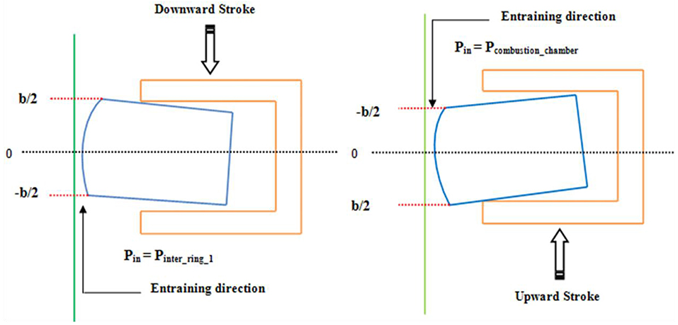
Figure 4. Oil flow and pressure boundary conditions for upward and downward stroke.
Thus, p = pin at x = –b/2. Ring rest on top land during upward stroke (compression and exhaust). While, it rests on bottom land during downward stroke. The inlet pressure is that of combustion chamber pressure during upstroke motion, while in downward stroke it is first inter ring gas pressure for a three ring piston assembly. For single ring piston assembly, it is that of crank case. Film rupture point at the outlet is applied to Swift-Stieber boundary condition as p = pc and dp/dx = 0 at x = xc. Where pc is the cavitation pressure at oil film rupture position (see Figure 4).
The inlet lubricant temperature calculated from convection from solid surface into the bulk oil temperature. The temperature rise across the film is due to conduction and convection. Along the direction of entrainment due to frictional heating. The inlet temperature due to frictional heating is the environmental temperature at the inlet. The temperature at h = 0 is the temperature of the ring or the skirt. Similarly at h = hmax, the temperature is the temperature of the cylinder.
The stepwise iterative procedure and associated convergence criteria in isothermal pressure, film temperature, thermal pressure, and film load are given as:
where Fap = Fe + Fg. To satisfy this convergence criterion appropriate relaxation of the film is carried out:
Result Analysis
Racing vehicles are designed to perform for high speed and high torque requirement. In these extreme operating conditions, the components manufactured by OEMs are tested for durability. Racing car engine differs from commercially used ones by the means that the former one has life of <1,500 km, while the later runs more than 200,000 km prior to the total overhauling. Endurance strength, lubricant stability etc. are tested with better accuracy through racing test. Therefore, we simulate our result using data of racing car engine.
Validation of Result
The important parameter of the analysis is the temperature of lubricant film in the ring-bore conjuction. The computed temperature needs to be validated. The model is simplified to a unidirectional sliding contact to validate with available result from Jang and Chang (1988) in the literature. The comparison graph plotted in the Figure 5 shows a good agreement between simulated output and standard data.
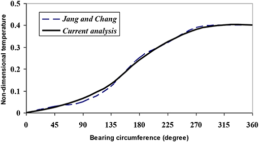
Figure 5. Validation of temperature.
Input Data for High Performance Engine Application
The piston compression ring with parabolic face profile is used with an offset ratio of 1.5 μm. The ring has nominal diameter of 82.2 mm and an axial width of 2 mm. It also has a ring radial depth of 3 mm. The material properties of ring such as modulus of elasticity is 203 GPa and poissons ratio is 0.23. The engine to which this compression ring is fitted runs with an operating speed of 13,000 rpm. The maximum combustion pressure of 120 bar is developed in the engine. The ring tension due to outward springing action is 10 N. The engine is assumed to use lubricant with viscosity 0.004 Pas at 100°C and piezo viscosity index of 10−8 Pa−1. Liner is considered to be with isotropic roughness and having Rk value of 0.49 μm.
Result Discussions
The thermal model of piston compression ring and cylinder contact is simulated for the racing car case. The difference between the commercial engine or passenger car engine and the racing car engine is that the previous one is having life up to 100,000 miles while the later one is having life <1,500 miles. Racing car engines are made for extreme operating condition to win the race, while the commercial engines are designed for durability and safety. Most OEMs test their component in race environment before engaging the original equipments to the use of passenger or commercial vehicle.
Conformability as discussed earlier is termed as the ability of a flexible ring to conform on the bore surface during installation and operation with minimum gap. Due to non-uniform sectional material strength and error in measurement, the degree of conformability in the free state sometimes varies and not necessarily agrees with the numerical finding (see Figure 6). Combustion gas pressure in engine shows a cyclic variation and regulates the sealing action. The burnt gas enters to back of the ring through orifice and develops ring back pressure.
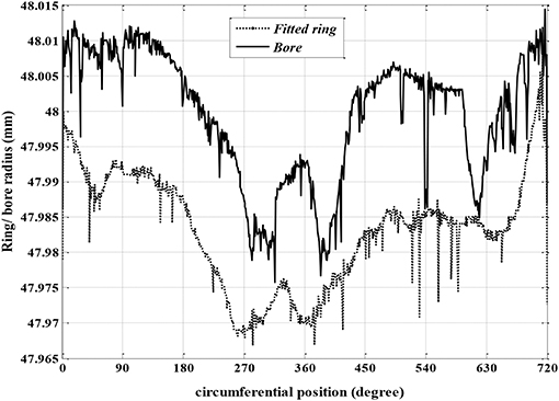
Figure 6. Freely conforming ring-bore.
With application of gas pressure, it is found that the gap of non-conforming ring-bore reduces with increasing value of gas pressure (see Figure 6). During an engine cycle, such conformability issue rises. It is obvious for this analysis that though the ring-liner conjunction runs in hydrodynamic regime in most part of engine cycle, asperity contact due to mixed/boundary regime also happens in crank angle range 300–400° (Mishra, 2012).
At highest gas pressure, the ring is fully conforming only leaving a gap of 10 μm at a small arc of the ring, which is within the free end gap. The 3-D film profile plotted in Figures 7A–D represents that in suction, compression, power, and exhaust, respectively. It suggests the effect of gas pressure is dominant in compression and power stroke. Hence, the mesh plot given indicates more conformance of ring bore resulting thinner film (0.25 μm) in conjunction in these strokes. While, in suction and exhaust stroke the back pressure force is dominated by ring tension with 10–12 kN of radial force in the ring. It results reduced ring-bore conformance and thicker film (1.5–2.5 μm).
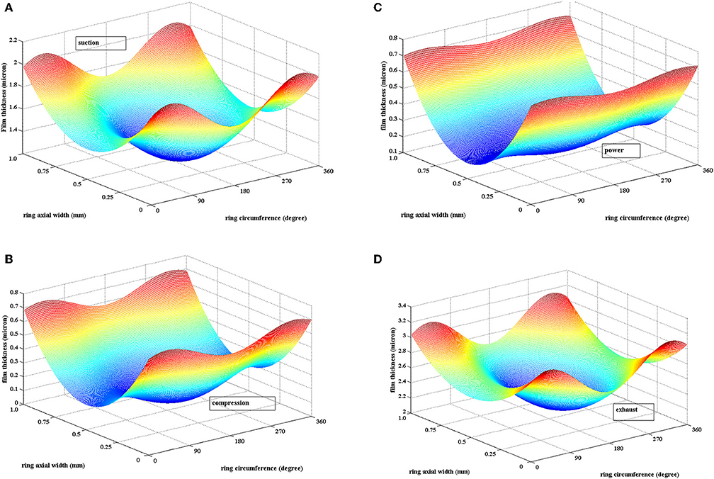
Figure 7. Three dimensional film thickness: (A) Suction stroke, (B) Compression stroke, (C) Power stroke, and (D) exhaust stroke. (A) Suction stroke (θc = 90°, Pcom = 5 bar, η0 = 0.004 Pa.s, U = 25 m/s). (B) Compression (θc = 250°, Pcom = 95 bar, η0 = 0.004 Pa.s, U = 20 m/s). (C) Power (θc = 273°, Pcom = 120 bar, η0 = 0.004 Pa.s, U = 5 m/s). (D) Exhaust stroke (θc = 620°, Pcom = 5 bar, η0 = 0.004 Pa.s, U = 25 m/s).
Due to increasing aerial conformance and reduced film thickness, Striebeck oil film parameter suggests that asperity tip interaction is significant in compression and power stroke. It leads to development of contact pressure (see Figures 8A,B). Mishra et al. (2009) presented the asperity contact pressure and friction to study its contribution in total friction loss. In this study, we plotted contour of asperity contact pressure in 305° (compression) and 373° (power) crank location, derived as per Equation (17) in Figures 7A,B. The maximum asperity contact pressure in the grid occurs at 160° < θc < 220° and 0.3 < b < 0.6 mm areal location with a value of 1.5–2.5 MPa.
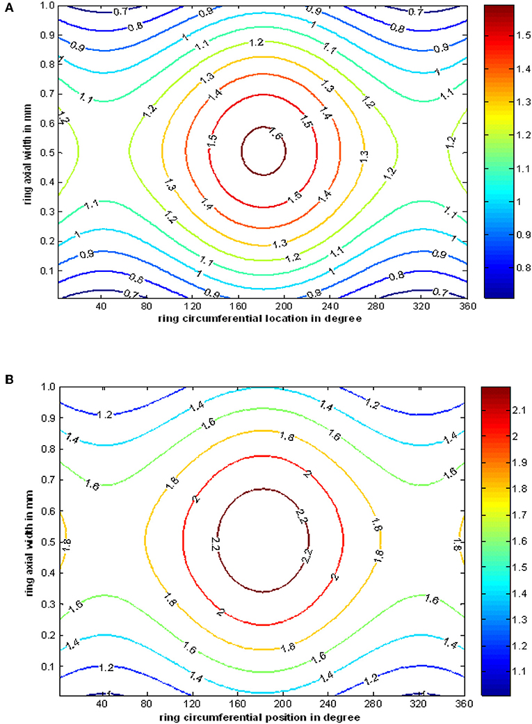
Figure 8. Contour of asperity contact pressure in MPa at higher gas loading, for (A) compression stroke (θc = 250°, Pcom = 95 bar, η0 = 0.004 Pa.s, U = 20 m/s) and (B) power stroke (θc = 273°, Pcom = 120 bar, η0 = 0.004 Pa.s, U = 5 m/s).
Compression ring and cylinder liner contact is fluid structure interaction type contact. The shearing stress developed in the film due to combined effect of viscous action and asperity interaction. In mixed regime, such shear stress is defined as per (Patir and Cheng, 1979) and is given in Equation (20). Due to appearance of roughness geometry, the average flow Reynolds equation based solution for shear stress carries some flow factors. Figures 9A–D states the contour of shear stress on film. In the cavitation region such shear stress is mostly uniform.
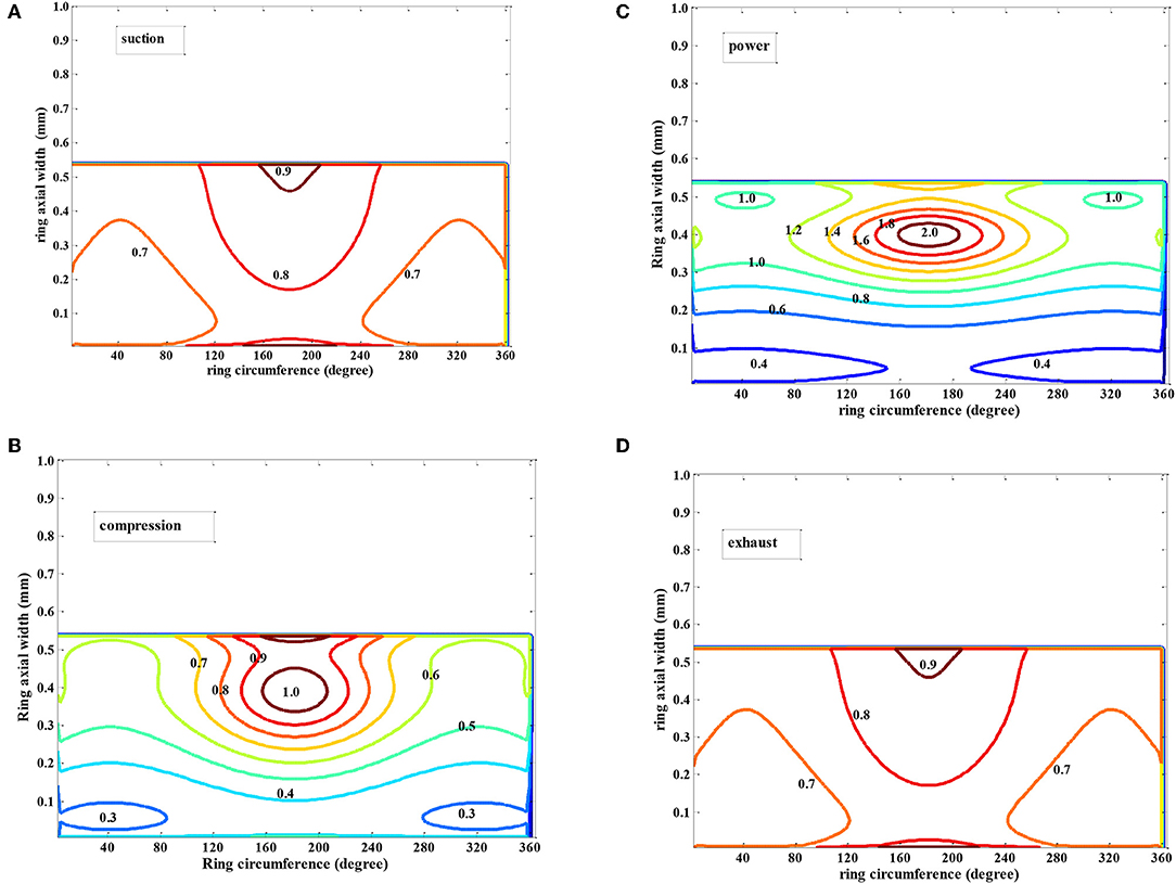
Figure 9. Contour plot of shear stress variation in fluid film: (A) Suction stroke, (B) Compression stroke, (C) Power stroke, and (D) exhaust stroke. (A) Suction stroke (θc = 90°, Pcom = 5 bar, η0 = 0.004 Pa.s, U = 25 m/s). (B) Compression (θc = 250°, Pcom = 95 bar, η0 = 0.004 Pa.s, U = 20 m/s). (C) Power (θc = 273°, Pcom = 120 bar, η0 = 0.004 Pa.s, U = 5 m/s). (D) Exhaust stroke (θc = 90°, Pcom = 5 bar, η0 = 0.004 Pa.s, U = 25 m/s).
Film temperature as given in Equation (9) is a function of hydrodynamic/elastohydrodynamic pressure. Further, as this pressure changes from one crank location to other, the film temperature also varies. Temperature variation in oil film in a particular crank location is a 3-D parameter. For clear understanding, section distribution and corresponding film thickness are plotted in both axial and circumferential direction (see Figures 10–13). In the axial direction, the maximum temperature rise in lubricant is happened at the position of minimum film thickness. In the circumferential direction, the minimum film thickness occurs at the position of minimum radial deformation. Hence it is predicted that lubricant temperature rise bears inverse relationship with ring global deformation (see Figure 11A).
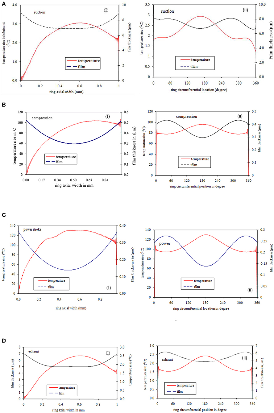
Figure 10. (A) Film and temperature variation in suction stroke (θc = 90°, Pcom = 5 bar, η0 = 0.004 PaS, U = 25 m/s). (B) Film and temperature variation in compression stroke (θc = 250°, Pcom = 95 bar, η0 = 0.004 PaS, U = 20 m/s). (C) Film and temperature variation in compression stroke (θc = 273°, Pcom = 120 bar, η0 = 0.004 PaS, U = 5 m/s). (D) Film and temperature variation in compression stroke (θc = 620°, Pcom = 5 bar, η0 = 0.004 PaS, U = 25 m/s).
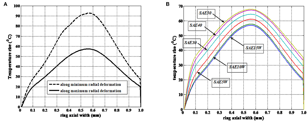
Figure 11. (A) Temperature rise variation due to radial deformation (θc = 273°, Pcom = 120 bar, η0 = 0.004 PaS, U = 5 m/s). (B) Temperature rise variation due to oil type (θc = 273°, Pcom = 120 bar, η0 = 0.004 PaS, U = 5 m/s).
More radial deviation means less ring-bore conformance and less minimum film thickness. Minimum film thickness is least at position opposite to the free end. Temperature rise due to maximum radial deformation is 45% less than that due to minimum radial deformation.
The response of rheological changes of lubricant and its effect on temperature rise is studied by modeling few SAE grade oils (see Figure 11B). Lubricant viscosity is considered to be a key performance parameter and varies due to combined effect of hydrodynamic pressure and oil-layer temperature. Significant variation in viscosity in such case is found to occur in compression and power stroke (see Figures 12A–D).
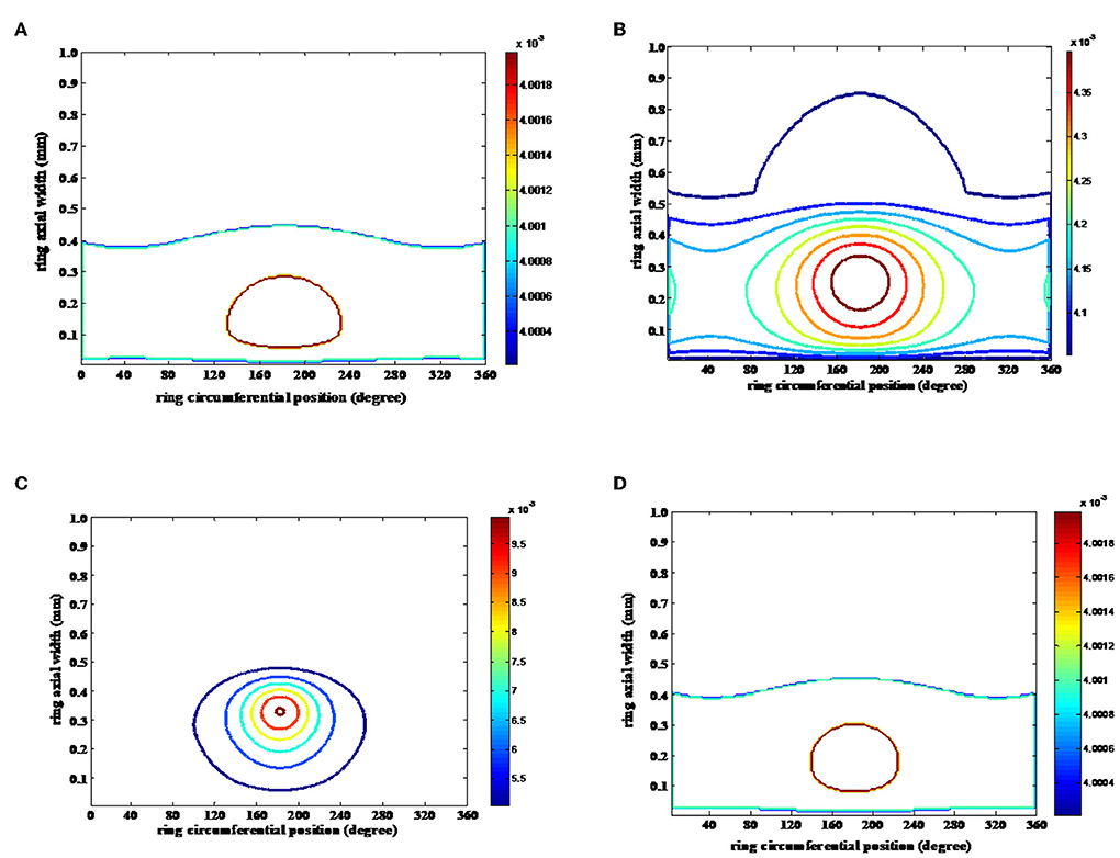
Figure 12. Viscosity variation contour mapping. (A) Suction, (B) compression, (C) power, and (D) exhaust.
Figure 13 presents the cyclic variation of velocity (Figure 13A), lubricant pressure (Figure 13B), and viscosity (Figure 13C) in an engine cycle. The viscosity shows a soaring high value in high pressure zone of compression and power stroke transition. Though there should be decrease in viscosity due to increase in temperature, but simultaneously there is increase in lubricant pressure. The net effect leads to increase in viscosity.
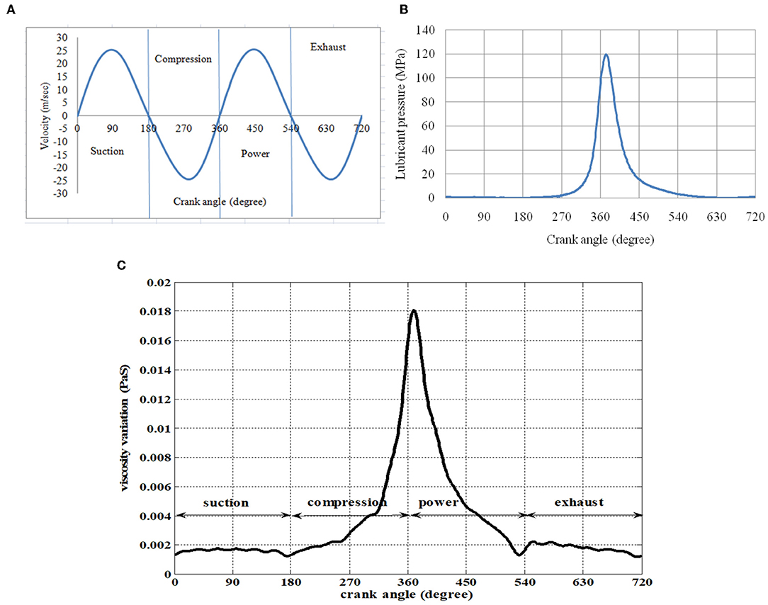
Figure 13. (A) Cyclic variation of piston sliding velocity in an engine cycle. (B) Cyclic variation of lubricant film pressure in an engine cycle. (C) Cyclic variation of viscosity in an engine cycle.
The lubrication phenomena in piston compression ring and cylinder liner conjunctions occur due to many parameters. Those include, film thickness, entraining velocity, bore geometry (micro-geometry such as surface roughness and macro geometry such as bore out-of-roundness), ring geometry, hydrodynamic pressure, asperity contact pressure, lubricant rheological parameters (temperature, density, and viscosity) the interdependency of such parameters are quite complex, some parameters are very sensitive to induce higher temperature, such as sliding velocity and bore roughness. While others have little/ negligible effect on film temperature. The most influential parameters being the sliding speed gas pressure. Particular values of these parameters are designated to specific crank locations as presented in Figures 8–13.
Conclusion
Estimation of lubricant temperature rise is the prime step for further thermal analysis of any conjunction. This validated model is best investigated for compression ring liner conjuction, including ring global deformation. The future work of friction analysis can be better explained through implementation of thermal effect on lubricated conjunction of compression ring and cylinder liner contact. The summary of the conclusion in this research is:
• The temperature rise in the film is affected by sliding velocity change and also due to variation in combustion chamber gas pressure. It is observed that there is maximum temperature rise of 120°C at 273° crank location, which is in power stroke region.
• There is a temperature near to 30°C between the maximum and minimum radial deformation position of the circumferentially deformed ring.
• There is estimated 10°C difference due to use of SAE15 and SAE50W oil, where in later case the temperature rise is more.
• Due to combined effect of hydrodynamic pressure and temperature rise, the viscosity is still rising and four to five times to the reference value.
The temperature and heat transfer of the piston subsystem and cylinder liner is a very complex phenomenon in transient state. It is due to the complex temperature boundary condition and component material variation. For example, head of piston is in side of combustion chamber (650°C) and the bottom is toward the crank case (100°C). Further, the material of piston is aluminum alloy, while that of cylinder liner is of steel. Such faster changing boundary condition if implemented will improve the current model to significant level.
Data Availability Statement
The datasets generated for this study are available on request to the corresponding author.
Author Contributions
PM has simulated the program, wrote the paper, and communicate it as single author.
Conflict of Interest
The author declares that the research was conducted in the absence of any commercial or financial relationships that could be construed as a potential conflict of interest.
Supplementary Material
The Supplementary Material for this article can be found online at: https://www.frontiersin.org/articles/10.3389/fmech.2019.00068/full#supplementary-material
References
Abe, S., and Suzuki, M. (1995). Analysis of Cylinder Bore Distortion During Engine Operation. SAE Technical Paper 950541. doi: 10.4271/950541
Akalin, O., and Newaz, G.M. (2001b). Piston ring cylinder bore friction modelling in mixed lubrication regime: Part. II-Correlation between bench test data. ASME J. Tribol. 123, 219–223. doi: 10.1115/1.1286338
Akalin, O., and Newaz, G. M. (2001a). Piston ring cylinder bore friction modelling in mixed lubrication regime: Part. I-analytical results. ASME J. Tribol. 123, 211–218. doi: 10.1115/1.1286337
Asaulyak, A. A., Rozhdestvenskii, Y. V., and Gavrilov, K. V. (2016). Elastohydrodynamic Lubrication (EHL) of piston rings in the internal combustion engine. Elsevier Proc. Eng. 150, 536–540. doi: 10.1016/j.proeng.2016.07.037
Baker, C. E., Rahnejat, H., Rahmani, R., and Theodossiades, S. (2011). Analytical Evaluation of Fitted Piston Compression Ring Modal Behaviour and Frictional Assessment. SAE International, SAE Paper No. 2011-01-1535. doi: 10.4271/2011-01-1535
Balakrishnan, S., and Rahnejat, H. (2005). Isothermal transient analysis of piston skirt-to-cylinder wall contacts under combined axial-lateral-tilting motion. J. Phys. Appl. Phys. D Appl. Phys. 38, 787–799. doi: 10.1088/0022-3727/38/5/018
Bolander, N. W., Steenwyk, B. D., Sadeghi, F., and Gerber, G. R. (2005). Lubrication regime transitions at the piston ring-cylinder liner interface. Proc. IMechE. Part J J. Tribol. 129, 19–31. doi: 10.1243/135065005X9664
Dowson, D., and Higginson, G. R. (1959). A numerical solution to the elastohydrodynamic problem. J. Mech. Eng. Sci. 10, 6–15. doi: 10.1243/JMES_JOUR_1959_001_004_02
Dowson, D., Ruddy, B. L., and Economou, P. N. (1983). Elasto hydrodynamic lubrication of piston rings. Proc. R. Soc. 386, 409–430. doi: 10.1098/rspa.1983.0043
Finol, C. A., Parker, D. A., and Robinson, K. (2009). A model from first principles of the radial heat flux in a cylinder bore of a modern diesel engine. J. Therm. Sci. Eng. Appl. 1:031003. doi: 10.1115/1.4000583
Furuhama, S., and Sasaki, S. (1983). New Device for the Measurement of Piston Frictional Forces in Small Engines. SAE technical Paper 831284. doi: 10.4271/831284
Greenwood, J. A., and Tripp, J. H. (1970). The contact of nominally flat surfaces. Proc. Inst. Mech. Eng. 185, 625–633. doi: 10.1243/PIME_PROC_1970_185_069_02
Harigaya, Y, Suzuki, M., and Takiguchi, M. (2003). Analysis of oil film thickness on a piston ring of diesel engine: effect of oil film temperature. ASME J. Eng. Gas Turbines Power 125, 596–603. doi: 10.1115/1.1501078
Hill, S. H., and Newman, B. A. (1984). Piston Ring Designs for Reduced Friction. SAE Technical Paper, 841222. doi: 10.4271/841222
Houpert, L. (1985). New results of traction force calculations in elasto hydrodynamic contacts. Trans. ASME F J. Tribol. 107, 241–245. doi: 10.1115/1.3261033
Hu, Y., Cheng, H. S., Arai, T., Kobayashi, Y., and Ayoma, S. (1994). Numerical simulation of piston ring in Mixed lubrication-A non-axi-symmetrical analysis. ASME J. Tribol. 116, 470–478. doi: 10.1115/1.2928867
Jang, J. Y., and Chang, C. C. (1988). Adiabatic analysis of finite width journal bearing with non-Newtonian lubricant. Elsevier Wear 122, 63–75. doi: 10.1016/0043-1648(88)90007-5
Ma, M.-T., Smith, S., and Sherrington, I. (1995). A three dimensional analysis of piston ring lubrication, Part 2: sensitive analysis. Proc. IMechE Part J J. Eng. Tribol. 209, 15–27. doi: 10.1243/PIME_PROC_1995_209_402_02
Ma, M.-T., Smith, S., and Sherrington, I. (1996). Implementation of algorithm to model the starved lubrication of a piston ring in distorted bore: prediction of oil flow and onset of gas blow. Proc. IMechE Part J J. Eng. Tribol. 210, 29–44. doi: 10.1243/PIME_PROC_1996_210_475_02
Ma, Z., Henein, N. A., and Bryzik, W. (2006). A model for wear and friction in cylinder liners and piston rings. STLE Tribol. Trans. 49, 315–327. doi: 10.1080/05698190600678630
Mishra, P. C. (2012). Tribodynamic modelling of piston compression ring and cylinder liner conjunction in high pressure zone of engine cycle. Int. J. Adv. Manuf. Technol. 66, 1075–1085. doi: 10.1007/s00170-012-4390-y
Mishra, P. C. (2013). Modelling for friction of four stroke four cylinder petrol engine. Tribol. Ind. 35, 237–245.
Mishra, P. C., Balakrishnan, S., and Rahnejat, H. (2008). Tribology of compression ring-to-Cylinder contact at reversal. Proc Instn Mech Eng. Part J. Eng. Tribol. 222, 815–826. doi: 10.1243/13506501JET410
Mishra, P. C., Rahnejat, H., and King, P. D. (2009). Tribology of the ring–bore conjunction subject to a mixed regime of lubrication. Proc. Instn. Mech. Eng. Part C J. Mech. Eng. Sci. 223, 987–998. doi: 10.1243/09544062JMES1220
Mohamed, E. S. (2018). Performance analysis and condition monitoring of ICE piston-ring based on combustion and thermal characteristics. Appl. Therm. Eng. 132, 824–840. doi: 10.1016/j.applthermaleng.2017.12.111
Morris, N., Rahmani, R., Rahnejat, H., King, P. D., and Fitzsimons, B. (2013). Tribology of piston compression ring conjuction under transient thermal mixed regime of lubrication. Tribol. Int. 59, 248–258. doi: 10.1016/j.triboint.2012.09.002
Mufti, R. A., and Priest, M. (2005). Experimental evaluation of piston-assembly friction under motored and fired conditions in a gasoline engine. Trans. ASME 127, 826–836. doi: 10.1115/1.1924459
Oh, K. P., Li, C. H., and Goenka, P. K. (1987). Elasto hydrodynamic lubrication of piston skirts. Trans. ASME J. Tribol. 109, 357–361. doi: 10.1115/1.3261366
Okamoto, M., and Sakai, I. (2001). Contact Pressure Distribution of Piston Rings -Calculation based on Piston Ring Contour. SAE Technical Paper 2001-01-0571. doi: 10.4271/2001-01-0571
Patir, N., and Cheng, H. S. (1978). An average flow model for determining effects of three-dimensional roughness on partial hydrodynamic lubrication. ASME J. Tribol. 100, 13–17. doi: 10.1115/1.3453103
Patir, N., and Cheng, H. S. (1979). Application of average flow model to lubrication between rough sliding surfaces. ASME J. Tribol. 101, 221–230. doi: 10.1115/1.3453329
Peng, E., and Huang, S. (2017). Wear performance of cylinder liner surface texturing on cylinder liner-piston ring assembly. IMechE J. 232, 291–306. doi: 10.1177/2F1350650117713435
Rahmani, R., Theodossiades, S., Rahnejat, H., and Fitzsimons, B. (2012). Transient elastohydrodynamic lubrication of rough new or worn piston compression ring conjunction with an out-of-round cylinder bore. Proc. IMechE Part J J. Eng. Tribol. 226, 284–305. doi: 10.1177/1350650111431028
Shahmohamadi, H., Rahmani, R., Rahnejat, H., Garner, C. P., and King, P. D. (2013). Thermo-mixed hydrodynamics of piston compression ring conjunction. Tribol. Lett. 51, 323–340. doi: 10.1007/s11249-013-0163-5
Shimada, A., Harigaya, Y., Suzuki, M., and Takiguchi, M. (2004). An analysis of oil film temperature, oil film thickness and heat transfer on a piston ring of internal combustion engine: the effect of local lubricant viscosity. J. Eng. 113, 1790–1798. Available online at: https://www.jstor.org/stable/44723636
Söderfjäll, M., Herbst, H. M., Larsson, R., and Almqvist, A. (2017). Influence on friction from piston ring design, cylinder liner roughness and lubricant properties. Tribol. Int. 116, 272–284. doi: 10.1016/j.triboint.2017.07.015
Spencer, A., Almqvist, A., and Larsson, R. (2011). A numerical model to investigate the effect of honing angle on the hydrodynamic lubrication between a combustion engine piston ring and cylinder liner. Proc. IMechE Part J J. Eng. Tribol. 225, 683–689. doi: 10.1177/1350650111403867
Sun, D. C. (1991). A thermal elastic theory of piston ring and cylinder-bore contact. Trans. ASME J. Appl. Mech. 58, 141–153. doi: 10.1115/1.2897141
Usman, A., and Park, C. W. (2017). Numerical investigation of tribological performance in mixed lubrication of textured piston ring-liner conjunction with a non-circular cylinder bore. Tribol. Int. 105, 148–157. doi: 10.1016/j.triboint.2016.09.043
Xu, G., and Sadeghi, F. (1996). Thermal EHL analysis of circular contacts with measured surface roughness. ASME J. Tribol. 118, 473–82. doi: 10.1115/1.2831560
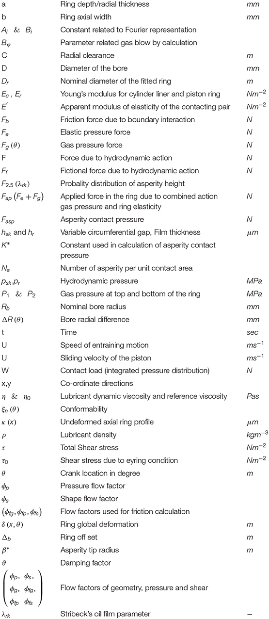
Notation
Appendix: I (Patir and Cheng Flow Factors)
The flow factors in any location are 3-D parameters. They are based on the Stribeck oil film parameter. The following flow factors are used in Reynolds Equation (9):
Pressure flow factor:
Shear flow factor:
Geometric flow factor:
The following flow factors are used in the shear stress Equation (10):
Pressure-induced flow factor:
Shear-induced flow factor:
And for topographical flow factor:
For: λrk ≤ 3
For: λrk > 3
where: , , and
All the constants used in the above flow factors are taken from (Patir and Cheng, 1978) for an isotropic surface.
Keywords: ring, liner, thermal model, temperature profile, lubricant film
Citation: Mishra PC (2020) Thermal Modeling of Thin Lubricant Film Within Piston Compression Ring and Rough Cyliner Liner Conjuction. Front. Mech. Eng. 5:68. doi: 10.3389/fmech.2019.00068
Received: 28 June 2019; Accepted: 05 December 2019;
Published: 22 January 2020.
Edited by:
Yu Tian, Tsinghua University, ChinaReviewed by:
Zhinan Zhang, School of Mechanical Engineering, Shanghai Jiao Tong University, ChinaZhiwei Guo, Wuhan University of Technology, China
Copyright © 2020 Mishra. This is an open-access article distributed under the terms of the Creative Commons Attribution License (CC BY). The use, distribution or reproduction in other forums is permitted, provided the original author(s) and the copyright owner(s) are credited and that the original publication in this journal is cited, in accordance with accepted academic practice. No use, distribution or reproduction is permitted which does not comply with these terms.
*Correspondence: Prakash Chandra Mishra, cHJhYmFzbWlzaHJhNzNAZ21haWwuY29t