 Yuha Koike1†
 Takeshi Hayakawa
- 1Department of Precision Engineering, Chuo University, Tokyo, Japan
- 2Toyama Industrial Technology Research and Development Center, Toyama, Japan
We present a driving method for on-chip hydrogel microactuators developed to be used for single-cell manipulations. The hydrogel actuator is composed of a temperature-responsive gel coated on a glass substrate with light-absorbing micropatterning. The actuator is driven by light irradiation, which increases its temperature. The advantage of this driving method is two-fold: allowing local heating of the actuator while decreasing heat dissipation to the substrate and its environment. The local heating induced by light irradiation improves the response characteristics of the hydrogel microactuator because the slight increase in environmental temperature aids cooling of the microactuator when the light is turned off. Furthermore, local heating enables multiple actuators to be located in close proximity without unintentionally actuating neighboring actuators through heat dissipation. In addition, the heating induced by the light irradiation does not require wiring on the chip. Therefore, the developed driving method enables the integration of a large number of actuators that can be independently driven on a single chip.
1. Introduction
Recently, the demands of single-cell analysis have increased with the evolving requirements from fields including medicine, cell biology, and biomedical research. Single-cell manipulation techniques are essential when analyzing single cells. For example, single-cell isolation from a large number of cells is a mandatory first step in single-cell analysis (Lindström and Andersson-Svahn, 2010; Gross et al., 2015). Single-cell transportation and trapping are also essential when performing analyses in which a target cell is moved and then fixed for precise analysis (Tottori et al., 2012; Yasa et al., 2019). Furthermore, more complex single-cell manipulations, such as the mechanical stimulation of a single cell (Itabashi et al., 2012) or a single-cell pairing (Teshima et al., 2010), are needed for the development of new analysis methods and to obtain novel biological findings.
Various conventional methods for single-cell manipulation have been proposed. Mechanical micromanipulation is the most popular method to manipulate single cells (Yanagida et al., 1999). This approach uses a mechanical micromanipulator with multiple degrees of freedom (DOF) to achieve high positioning accuracy. Micromanipulators can be equipped with various end effectors such as glass capillaries with diameters of 100 nm to 100 μm that are connected to external pumps. A capillary enables target cells to be fixed, cut, or injected with DNA or RNA. Other types of end effectors, such as microelectromechanical sensors (Bell et al., 2005; Kim et al., 2006) and nanoneedles (Obataya et al., 2005), on micromanipulators allow mechanical or electrical characteristics of cells to be measured. Thus, mechanical micromanipulators can perform flexible and various single-cell manipulations. As a result, they are widely used in practical biomedical applications. However, mechanical micromanipulation requires expert operators. Thus, such manipulation tends to have low throughput and the results may often have low repeatability.
Another type of single-cell manipulation is on-chip cell manipulation, which uses a microfluidic chip as a platform for single-cell manipulation (Yeo et al., 2011). A microfluidic chip possesses a microchannel and may contain integrated sensors and/or actuators. In the microchannel, the DOF of target cells is decreased to one or two. In other words, the positions of target cells are confined in a 1D microchannel or 2D microchamber. The combination of confinement of the target cell position in microspace and the integration of actuators or sensors on the chip enable high-throughput and highly repeatable single-cell manipulations for single-cell analysis. Therefore, on-chip single-cell manipulations based on various principles such as electric (Fiedler et al., 1998; Gascoyne and Vykoukal, 2002), magnetic (Miltenyi et al., 1990; Jiang et al., 2006), optical (Ashkin et al., 1987; Onda and Arai, 2012), and acoustic (Shi et al., 2009; Ding et al., 2012) forces have been proposed.
On-chip single-cell manipulations can be categorized into contact and non-contact. Contact manipulation uses the direct contact of mechanical structures with target cells, similar to a mechanical micromanipulator. For on-chip cell manipulations, on-chip actuators and microrobots driven by magnetic (Sakuma et al., 2009; Hagiwara et al., 2011; Nakahara et al., 2015), optical (Onda and Arai, 2012), and piezoelectric (Ito et al., 2016; Sakuma et al., 2019) forces have been used. Such actuators and microrobots enable cell manipulation with high positioning accuracy through strong forces. For example, Sakuma et al. realized the continuous measurement of the mechanical characteristics of cell spheroids using a silicon-based on-chip actuator (Sakuma et al., 2019). However, contact manipulation has the problem of cell adhesion to the mechanical structures, which may cause mechanical damage when the target cells and mechanical structures are in contact. In contrast, non-contact manipulation has less risk of mechanical damage and cell adhesion. Therefore, non-contact manipulation based on fluidic, electrical, optical, or acoustic forces has been used for trapping (Ashkin et al., 1987; Onda and Arai, 2012), patterning (Shi et al., 2009), separation (Yang et al., 1999), and rotation (Benhal et al., 2014) of single cells. However, the force involved in non-contact manipulation is generally weak. Therefore, applications of non-contact manipulations are limited.
To overcome these problems, contact manipulation of single cells based on soft microactuators has been studied. Soft materials such as hydrogels have a softness (≈10 kPa; Matzelle et al., 2002; Harmon et al., 2003) more similar to that of cells (≈1 kPa; Cross et al., 2008; Faria et al., 2008) than other materials used for contact manipulations, such as a silicon (≈ GPa) or photoresists (≈ MPa). Thus, contact manipulation with soft actuators may protect subject target cells from mechanical damage. Furthermore, the surfaces of hydrogels mitigate cell adhesion because of their hydrophilic characteristics. Therefore, single-cell manipulations using a hydrogel microactuator fabricated on a microfluidic chip have been intensively researched (Arai et al., 2003, 2005; Ichikawa et al., 2005; Yokoyama et al., 2011; Hayakawa et al., 2014; Ito et al., 2014).
Hydrogel microactuators are commonly constructed from poly(N-isopropylacrylamide) (PNIPAAm). PNIPAAm is a thermo-responsive gel that swells by absorbing water when the temperature is lower than its transition temperature (≲ 32°C). Conversely, PNIPAAm shrinks when its temperature is higher than this transition temperature, as shown in Figure 1A. Thus, by controlling the temperature of PNIPAAm, we can use the induced volumetric change as the displacement of an actuator. The conventional driving method of a PNIPAAm-based microactuator uses an integrated microheater (Arai et al., 2005; Hayakawa et al., 2014; Ito et al., 2014), as shown in Figure 1B. By applying an electric voltage to a patterned microheater located under a gel actuator, the temperature of the gel actuator can be increased through Joule heating. Natural heat dissipation to the environment is used to cool and thereby swell the actuator. Using an on-chip gel actuator driven by a microheater, single cells can be fixed, transported, sorted, and trapped (Arai et al., 2005; Hayakawa et al., 2014; Ito et al., 2014).
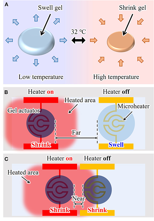
Figure 1. On-chip hydrogel microactuator: (A) working principle, (B) conventional drive method, and (C) a problem of conventional drive method due to heat dissipation when the actuators are integrated in short distances.
However, when using a microheater, environmental temperature is inevitably increased because of temperature increases in the electrode wiring. Subsequently, a neighboring actuator is heated slightly even if its microheater is turned off, as shown in Figure 1C. Thus, to realize independent driving, sufficient separation between multiple actuators is required, which limits the number of actuators that can be integrated on one chip. Furthermore, it is difficult to integrate a large number of actuators on one chip because each actuator needs its own microheater, which should be isolated when patterned. Currently, the integration of up to 10 actuators is possible, but the integration of 100 to 1,000 or more actuators with microheaters is very difficult in practice. Therefore, a new driving method for on-chip gel actuators is strongly desired to achieve large-scale integration of actuators and independent actuation.
In this work, we propose using light irradiation as a driving method for an on-chip hydrogel microactuator. This method enables highly localized heating of an on-chip microactuator without any wiring. Additionally, this approach decreases the heat dissipation from an actuated part to the local environment because of its high thermal localization. Such heat localization enables multiple actuators to be integrated on a small area of a chip while still allowing each actuator to be driven independently. Furthermore, this driving method improves the response characteristics of the actuator. In the next section, we describe the concept of this driving method and explain its underlying principle. We evaluate the response characteristics of a light-driven actuator and compare them with those of a microheater-driven actuator. We then confirm the independent actuation of the actuators with short distance when driven by light irradiation. Finally, we demonstrate the massive integration of microactuators that function independently, and examples of cell manipulations.
2. Concept
Our driving method for on-chip gel actuators uses light irradiation. By fabricating light-absorbing patterns under the gel actuators and then irradiating an actuator with light, local heating of a gel actuator is achieved, as shown in Figure 2a. Using focused light, this driving method induces highly localized heating of individual actuators. Thus, multiple actuators can be integrated with separation distances that are shorter than those of microheater-driven actuators and with less heat dispersed into the local environment. Furthermore, because there is no complex wiring, a large number of actuators can be integrated on a single chip, as illustrated in Figure 2b. Therefore, various cell manipulations can be realized by integrating multiple actuators on a chip and independently driving them, as shown in Figure 2c. In this study, as examples of single-cell manipulations, we integrated gel actuators in a square array and demonstrated trapping and applied mechanical stimulations of single motile cells.
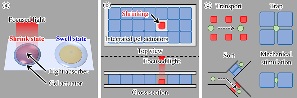
Figure 2. Proposed concept of using light irradiation as a driving method for a gel actuator: (a) principle, (b) actuation of a single hydrogel actuator in an assembly of multiple actuators, and (c) examples of various single-cell manipulations using the proposed method.
3. Experiments
3.1. Experimental System
An infrared (IR) laser (LuxX 1060-150, Omicron-Laserage Laserprodukte GmbH, Rodgau-Dudenhofen, Germany; wavelength: 1,060 nm, maximum power: 150 mW) was used as the light source to drive the gel actuators, as shown in Figure 3. The IR laser was focused using an objective lens (Plan N 10x/0.25na, Olympus, Tokyo, Japan). Microscopic images were recorded using a charge-coupled device camera (BFS-U3-32S4, FLIR Systems Japan K.K., Tokyo, Japan). To evaluate the frequency response of the actuator, we input a square wave of 0.1–10 Hz to the laser controller. With this input signal, the IR laser was switched ON/OFF at a rate equal to the input frequency.
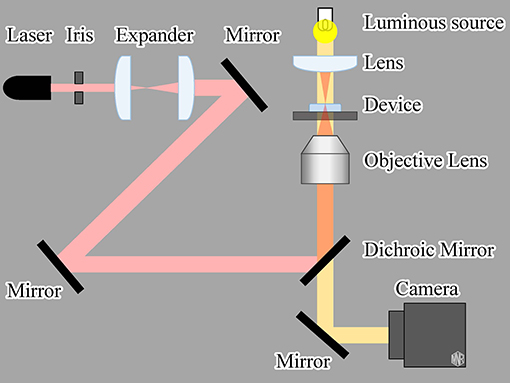
Figure 3. Experimental setup of the light-driven gel actuator system.
We also evaluated the characteristics of a microheater-driven actuator as a reference. Similar to light-driven irradiation, we applied a square-wave electric voltage of various frequencies to the microheater. The input signal was generated using a digital to analog converter board (PEX-340416, Interface Co. Ltd., Hiroshima, Japan) installed in the control PC.
3.2. Fabrication Process of the Actuator
We fabricated the actuator using the following process (Figure 4):
(a) Chromium (Cr) and gold (Au) or Cr are deposited on glass substrate by using vapor deposition.
(b) OFPR (OFPR-800, Tokyo Ohka Kogyo Co. Ltd., Kanagawa, Japan) is patterned on a Cr/ Au layer as an etching mask.
(c) Cr/ Au or Cr layers are etched.
(d) OFPR is removed.
(e) PNIPAAm is spin coated.
(f) PNIPAAm is patterned.
We fabricated hydrogel microactuators that could be driven by both a microheater and light irradiation to aid comparison of their actuation characteristics. The microheater was fabricated from Cr/ Au to provide low electrical resistance. We used only Cr rather than Cr/Au for the light-absorbing patterns because only a good light-absorbing material such as Cr is required in the light-driven method. For patterning of PNIPAAm, we used photo-processable PNIPAAm (Bioresist, Nissan Chemical Corporation, Tokyo, Japan).
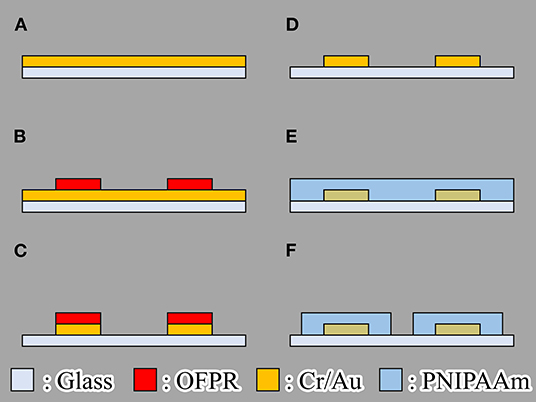
Figure 4. Fabrication process of the gel microactuator. (A) Chromium (Cr) and gold (Au) or Cr are deposited on glass substrate by using vapor deposition. (B) OFPR (OFPR-800, Tokyo Ohka Kogyo Co. Ltd., Kanagawa, Japan) is patterned on a Cr/Au layer as an etching mask. (C) Cr/Au or Cr layers are etched. (D) OFPR is removed. (E) PNIPAAm is spin coated. (F) PNIPAAm is patterned.
3.3. Design of Microheater and Light-Absorbing Pattern
Using the design of the microheater and light-absorbing patterns in Figure 5, we measured and then compared the driving characteristics of the actuators driven by the microheater and light irradiation. We applied the same amount of heat to both actuators.
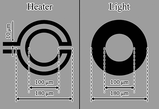
Figure 5. Design of the microheater and light-absorbing pattern for the gel microactuator.
The width and length of each microheater were 10 and 963 μm, respectively. The light-absorbing pattern consisted of a ring with inner and outer diameters of 100 and 180 μm, respectively. Using a laser power meter (3A-P, Ophir Optronics Solutions Ltd., Jerusalem, Israel), we also determined the light absorption rate of a Cr layer by measuring the laser power before and after transmission through the Cr layer. The light absorption rate of the fabricated Cr layer was approximately 98%. Therefore, the absorbed light energy Q on the Cr pattern was calculated to be
where D is the diameter of the focused laser beam, W is energy density, and A is the light absorption rate. We assumed that Q was the total amount of heat generated. We provided both microheater- and light irradiation-driven actuators with the same amount of heat to compare their driving characteristics. We set the applied voltage of the microheater to 3.3 V and the laser power to 150 mW. Under these conditions, approximately 51 mW of heat was applied to both types of actuators.
We patterned PNIPAAm in the form of a ring with inner and outer diameters of 30 and 220 μm, respectively, to form the gel actuator. This shape is intended to be used as a single-cell catcher, similar to previous work (Hayakawa et al., 2014). To evaluate response characteristics, we measured the size of the inner hole of the ring as the displacement of the actuator, which is explained in detail below.
4. Results
4.1. Evaluation of Drive Characteristics
First, we confirmed that the patterned actuator was driven by light irradiation (Figure 6). The fabricated ring pattern of PNIPAAm was swollen at room temperature and then shrunk upon irradiation with light. Hereafter, we define the displacement ratio of the actuators as
and use this ratio for comparison of the actuator drive characteristics. Here, dH(f) and dL(f) are the diameters of the hole in the PNIPAAm at high and low temperatures, respectively, at the frequency of the irradiated light or applied voltage f. In addition, dmax and dmin are the maximum and minimum diameters, respectively, of the hole of the actuator when driven by each actuation method at 0.1 Hz.
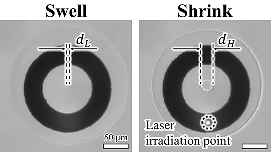
Figure 6. Microscopic image of a driven microactuator.
We evaluated the step response of the actuators, as shown in Figure 7A. In this evaluation, we measured the responses of three different samples for each driving method. For a single ON/OFF step of the voltage or light irradiation, the actuators driven by both actuation methods displayed similar response characteristics. Both actuators shrunk for approximately 0.3 s after switching on the microheater or light irradiation and swelled for approximately 1.2 s after switching the microheater or light irradiation off.
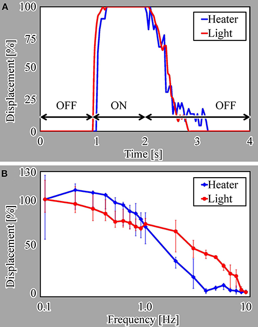
Figure 7. Actuation characteristics of the actuators: (A) step response and (B) frequency response.
We also evaluated the frequency response from 0.1 to 10 Hz for both actuation methods, as presented in Figure 7B. These results reveal that the light-driven actuator has better response characteristics than those of the microheater-driven actuator at most frequencies. This is because the heat dissipation from the microheater to the local environment is thought to be larger than that from light irradiation, as explained in section 1.
Here, we note that the displacement of the microheater-driven actuator exceeds 100% at lower frequencies, i.e., long ON times. This is thought to be due to overheating of the microheater, which did not cool sufficiently for the water to allow swelling of the actuator.
4.2. Evaluation of Heat Dissipation
To understand the difference in the response characteristics of the two actuators, we confirmed details of their displacements at 0.5 Hz. We plotted the displacements of each actuator for the initial ten steps from the start of the voltage or light application (Figure 8). In this evaluation, we also measured the responses of three different samples for each driving method. For the light-driven actuator, almost the same maximum displacement was observed during every ON phase. In addition, the displacement decreased to around 30% of the maximum displacement in every OFF phase. In contrast, for the microheater-driven actuator, the difference between the maximum and minimum displacement gradually diminished with increasing ON/OFF cycle number. This behavior indicates that the microheater-driven actuator did not cool sufficiently during the OFF phase of the 0.5-Hz heating cycle.
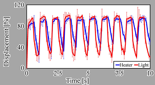
Figure 8. Initial ten cycles of actuators driven by both methods.
We also confirmed the thermal dissipation of the microheater and light irradiation using thermography (TiX560, Fluke South East Asia Pte Ltd, Clementi Loop, Singapore). We recorded the temperatures around both actuators (Figure 9) while applying the electric voltage or light irradiation for 1.0 s. For the microheater, the temperature of a large area around the microheater increased after 1.0 s and then rose further after turning off the microheater at 1.1 s (Figure 9a). In contrast, the temperature of a small area around the light-absorbing pattern increased after 1.0 s of light irradiation and then the temperature rapidly decreased after turning off the light irradiation at 1.1 s (Figure 9b). All frames recorded at 9 fps by the thermographic camera are available in Supplementary Data Sheet 1. These results showed that our driving method using light irradiation achieved more localized heating than the conventional method using a microheater. Furthermore, the decrease in temperature after turning the light irradiation off was much faster than that after switching off the microheater. This is the reason for the low frequency response of the microheater-driven actuator. These results indicate that it should be possible to integrate light-driven actuators with small separation distances without interfering operations from neighboring actuators.
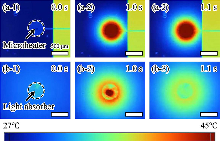
Figure 9. Thermographic images of actuators driven by (a) a microheater and (b) light irradiation.
4.3. Independent Driving of Actuators With a Short Separation Distance
Next, we confirmed the thermal transfer between two actuators separated by a short distance using both driving methods. The separation distance was 250 μm in both cases (Figure 1). We applied either an electric voltage or light irradiation to one actuator for 1.0 s and then observed the displacement of the other. The microheater-driven actuator was affected by its neighboring actuator, as shown in Figure 10a. In contrast, the light-driven actuator was affected less by its neighboring actuator than was the case for the microheater-driven actuator, as shown in Figure 10b. A video of this experimental evaluation is available in Supplementary Video 1. The different behavior of the actuators driven by the two methods is thought to be caused by the difference between the areas of thermal dissipation of the microheater and light irradiation (Figure 9). These results show that light-driven actuators can be integrated with shorter separation distances than those required for microheater-driven actuators. Overall, the favorable response characteristics and short integration distance obtained using our actuation method indicate that light irradiation provides more localized heating and better driving characteristics than those achieved using a conventional microheater.
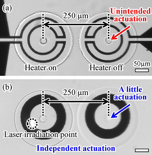
Figure 10. Integrability of two (a) microheater-driven and (b) light-driven actuators with a short separation distance.
5. Discussion
5.1. Evaluation of Cell Damage
One concern of the proposed method using light-driven gel actuators for cell manipulation is cell damage. Two types of cell damages may be caused by the proposed method. One is cell toxicity caused by materials such as Cr and the other is thermal damage to the cell caused by laser irradiation. Thus, we evaluated the occurrence of these two types of damage in the cells exposed to light-driven gel actuators. Details of the evaluation method and results are provided in Supplementary Data Sheet 2. Our results confirmed that the proposed method does not cause significant cell damages during normal use.
To minimize cell toxicity of Cr, we can coat the surface of the Cr layer with a noble metal such as Au or platinum (Pt). Additionally, we can also minimize thermal damage by applying an appropriate quantity of heat. That is, by using a lower laser power and shorter time, thermal damage should be suppressed. However, the response characteristics of the actuator are thought to be weakened when we use a lower laser power. And also, some applications such as long time trapping or culture might need laser irradiation for long time. Thus, designs of actuator shapes and/or conditions of laser irradiation should be properly determined for specific applications and target cell species.
5.2. Massive Integration of Gel Actuators
We demonstrated the massive integration of on-chip light-driven gel actuators and the mutual independence of actuators, as shown in Figure 11. We fabricated 25 × 25 = 625 actuators on a chip, as depicted in Figure 11a. The actuators were square in shape with a side length of 50 μm. The separation distance between actuators in the shrunken state was 20 μm. Upon immersing the actuators in water, the separation distance between them was filled by the swollen actuators. Thus, the side length of the swollen actuators was approximately 70 μm. We succeeded in driving just one actuator independently of all the other light-driven actuators on the chip, as shown in Figure 11b. A video of this experimental demonstration is available in Supplementary Video 2.
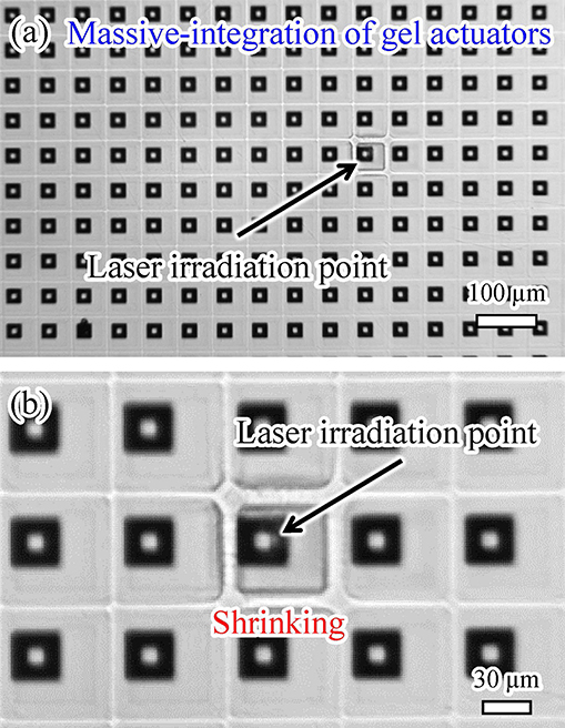
Figure 11. Massive integration of gel actuators: (a) overall view and (b) enlarged view.
Such massive integration with independent actuation is quite difficult using conventional microheater-driven actuators. These results reveal that our method is suitable for massive integration and independent actuation of on-chip hydrogel microactuators.
5.3. Demonstration of Cell Manipulation
Finally, we demonstrated single-cell manipulation using the light-driven integrated gel actuators. The trapping of motile cells was achieved, as shown in Figure 12. By exposing the array of actuators covered with glass to targeted laser irradiation, we were able to trap a motile cell in the gap between the actuators when we turned off the laser, as illustrated in Figures 12A–C. We then irradiated the actuators with the laser again to confirm the movement of the trapped cell to check its viability, as depicted in Figure 12D. We used Euglena as target motile cells. Additionally, we used the laser with larger spot size than the single actuator to get a larger trap area with multiple actuators, as shown in Figure 12.
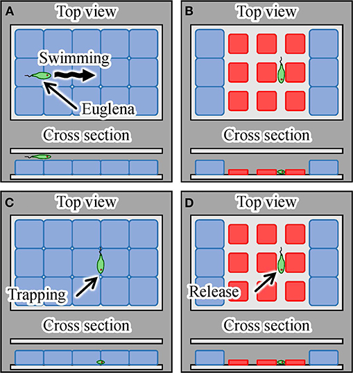
Figure 12. Trapping and mechanical stimulation of a single motile cell using integrated hydrogel actuators. (A) A motile Euglena cell, (B) trapping of a Euglena cell by turning on the laser, (C) trapping and mechanical stimulation of the cell by turning off the laser, and (D) release of the Euglena cell induced by turning on the laser.
Figure 13 shows microscopic images of the actual manipulation of Euglena cells. Euglena cells moved above the shrunken actuators, as shown in Figures 13a,b. We turned off the laser when a Euglena cell passed between the shrunken actuators, as shown in Figure 13c. In the absence of light irradiation, the actuators swelled and a Euglena cell was trapped between the actuators. We then turned the laser on and the actuators shrunk again, as shown in Figure 13d. The trapped Euglena cell was released and still moved. After its release, the Euglena cell exhibited peristaltic movement. This motion is known as euglenoid movement and is caused by mechanical stimulation (Mikolajczyk and Kuznicki, 1981). A video of the trapping and release of the Euglena cell is available in Supplementary Video 3.
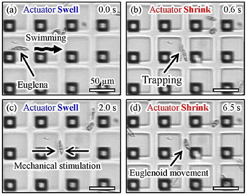
Figure 13. Experimental images of trapping and mechanical stimulation of a Euglena cell. (a) A motile Euglena cell, (b) trapping of the Euglena cell by turning on the laser, (c) trapping and mechanical stimulation of the cell induced by turning off the laser, and (d) release of the Euglena cell by turning on the laser.
These results reveal that we successfully trapped a single motile cell using the proposed actuation method.
6. Conclusions
We proposed a light irradiation-based driving method for on-chip microactuators made of a thermo-responsive gel for cell manipulations. The actuator was patterned on a glass chip with a light-absorbing pattern and was driven by irradiating the pattern with focused light. This driving method enabled highly localized heating of the microactuator and improved the response characteristics and integrability of the actuators on the chip compared with the case for conventional actuators driven by a microheater. We evaluated the drive characteristics and thermal dissipation of actuators exposed to light irradiation. We also demonstrated the integration of numerous actuators and the independent driving of a targeted actuator among them. Furthermore, we trapped a single motile cell as an example of cell manipulation using the proposed method. The irradiation of massively integrated gel actuators by patterned light to achieve parallel manipulation of single cells and the practical applications of such actuators in high-throughput single-cell analysis will be reported in the future.
Data Availability Statement
The datasets generated for this study are available on request to the corresponding author.
Author Contributions
YK and TH conceiving and designing the study, collecting data, performing the analysis and interpretation of data, drafting the manuscript, and critically revising the manuscript. YY helped design the study and critically revised the article. All authors read and approved the final manuscript.
Funding
This research was supported by a Chuo University Personal Research Grant.
Conflict of Interest
The authors declare that the material used in this study (Bioresist) was provided by Nissan Chemical Corporation. Nissan Chemical Corporation had no role in study design, data collection and analysis, decision to publish, or preparation of the manuscript.
Acknowledgments
The authors thank the Nissan Chemical Corporation for providing photo-processable PNIPAAm (Bioresist). We thank Natasha Lundin, Ph.D., from Edanz Group (www.edanzediting.com/ac) for editing a draft of this manuscript.
Supplementary Material
The Supplementary Material for this article can be found online at: https://www.frontiersin.org/articles/10.3389/fmech.2020.00002/full#supplementary-material
References
Arai, F., Ichikawa, A., Fukuda, T., and Katsuragi, T. (2003). Isolation and extraction of target microbes using thermal sol-gel transformation. Analyst 128, 547–551. doi: 10.1039/b212919a
Arai, F., Ng, C., Maruyama, H., Ichikawa, A., El-Shimy, H., and Fukuda, T. (2005). On chip single-cell separation and immobilization using optical tweezers and thermosensitive hydrogel. Lab Chip 5, 1399–1403. doi: 10.1039/b502546j
Ashkin, A., Dziedzic, J. M., and Yamane, T. (1987). Optical trapping and manipulation of single cells using infrared laser beams. Nature 330, 769–771. doi: 10.1038/330769a0
Bell, D., Sun, Y., Zhang, L., Dong, L., Nelson, B. J., and Grutzmacher, D. (2005). “Three-dimensional nanosprings for electromechanical sensors,” in The 13th International Conference on Solid-State Sensors, Actuators and Microsystems, 2005. Digest of Technical Papers. TRANSDUCERS'05, Vol. 1 (Seoul: IEEE), 15–18.
Benhal, P., Chase, J. G., Gaynor, P., Oback, B., and Wang, W. (2014). Ac electric field induced dipole-based on-chip 3D cell rotation. Lab Chip 14, 2717–2727.
Cross, S. E., Jin, Y.-S., Tondre, J., Wong, R., Rao, J., and Gimzewski, J. K. (2008). AFM-based analysis of human metastatic cancer cells. Nanotechnology 19:384003. doi: 10.1088/0957-4484/19/38/384003
Ding, X., Lin, S.-C., Kiraly, B., Yue, H., Li, S., Chiang, I.-K., et al. (2012). On-chip manipulation of single microparticles, cells, and organisms using surface acoustic waves. Proc. Natl. Acad. Sci. U.S.A. 109, 11105–11109. doi: 10.1073/pnas.1209288109
Faria, E. C., Ma, N., Gazi, E., Gardner, P., Brown, M., Clarke, N. W., and Snook, R. D. (2008). Measurement of elastic properties of prostate cancer cells using afm. Analyst 133, 1498–1500. doi: 10.1039/b803355b
Fiedler, S., Shirley, S. G., Schnelle, T., and Fuhr, G. (1998). Dielectrophoretic sorting of particles and cells in a microsystem. Analyt. Chem. 70, 1909–1915. doi: 10.1021/ac971063b
Gascoyne, P. R., and Vykoukal, J. (2002). Particle separation by dielectrophoresis. Electrophoresis 23, 1973–1983. doi: 10.1002/1522-2683(200207)23:13<1973::AID-ELPS1973>3.0.CO;2-1
Gross, A., Schoendube, J., Zimmermann, S., Steeb, M., Zengerle, R., and Koltay, P. (2015). Technologies for single-cell isolation. Int. J. Mol. Sci. 16, 16897–16919. doi: 10.3390/ijms160816897
Hagiwara, M., Kawahara, T., Yamanishi, Y., Masuda, T., Feng, L., and Arai, F. (2011). On-chip magnetically actuated robot with ultrasonic vibration for single cell manipulations. Lab Chip 11, 2049–2054. doi: 10.1039/c1lc20164f
Harmon, M. E., Kuckling, D., and Frank, C. W. (2003). Photo-cross-linkable PNIPAAm copolymers. 5. Mechanical properties of hydrogel layers. Langmuir 19, 10660–10665. doi: 10.1021/la030232m
Hayakawa, T., Sakuma, S., Fukuhara, T., Yokoyama, Y., and Arai, F. (2014). A single cell extraction chip using vibration-induced whirling flow and a thermo-responsive gel pattern. Micromachines 5, 681–696. doi: 10.3390/mi5030681
Ichikawa, A., Arai, F., Yoshikawa, K., Uchida, T., and Fukuda, T. (2005). In situ formation of a gel microbead for indirect laser micromanipulation of microorganisms. Appl. Phys. Lett. 87:191108. doi: 10.1063/1.2126800
Itabashi, T., Terada, Y., Kuwana, K., Kan, T., Shimoyama, I., and Ishiwata, S. (2012). Mechanical impulses can control metaphase progression in a mammalian cell. Proc. Natl. Acad. Sci. U.S.A. 109, 7320–7325. doi: 10.1073/pnas.1116749109
Ito, K., Sakuma, S., Kimura, M., Takebe, T., Kaneko, M., and Arai, F. (2016). Temporal transition of mechanical characteristics of HUVEC/MSC spheroids using a microfluidic chip with force sensor probes. Micromachines 7:221. doi: 10.3390/mi7120221
Ito, K., Sakuma, S., Yokoyama, Y., and Arai, F. (2014). On-chip gel-valve using photoprocessable thermoresponsive gel. ROBOMECH J. 1:5. doi: 10.1186/s40648-014-0005-8
Jiang, Z., Llandro, J., Mitrelias, T., and Bland, J. (2006). An integrated microfluidic cell for detection, manipulation, and sorting of single micron-sized magnetic beads. J. Appl. Phys. 99:08S105. doi: 10.1063/1.2176238
Kim, D.-H., Hwang, C. N., Sun, Y., Lee, S. H., Kim, B., and Nelson, B. J. (2006). Mechanical analysis of chorion softening in prehatching stages of zebrafish embryos. IEEE Trans. Nanobiosci. 5, 89–94. doi: 10.1109/TNB.2006.875054
Lindström, S., and Andersson-Svahn, H. (2010). Overview of single-cell analyses: microdevices and applications. Lab Chip 10, 3363–3372. doi: 10.1039/c0lc00150c
Matzelle, T., Ivanov, D., Landwehr, D., Heinrich, L. A., Herkt-Bruns, C., Reichelt, R., et al. (2002). Micromechanical properties of smart gels: studies by scanning force and scanning electron microscopy of pnipaam. J. Phys. Chem. B 106, 2861–2866. doi: 10.1021/jp0128426
Mikolajczyk, E., and Kuznicki, L. (1981). Body contraction and ultrastructure of euglena. Acta Protozool. 29, 1–24.
Miltenyi, S., Müller, W., Weichel, W., and Radbruch, A. (1990). High gradient magnetic cell separation with macs. Cytometry 11, 231–238. doi: 10.1002/cyto.990110203
Nakahara, K., Sakuma, S., Hayakawa, T., and Arai, F. (2015). On-chip transportation and measurement of mechanical characteristics of oocytes in an open environment. Micromachines 6, 648–659. doi: 10.3390/mi6050648
Obataya, I., Nakamura, C., Han, S., Nakamura, N., and Miyake, J. (2005). Nanoscale operation of a living cell using an atomic force microscope with a nanoneedle. Nano Lett. 5, 27–30. doi: 10.1021/nl0485399
Onda, K., and Arai, F. (2012). Multi-beam bilateral teleoperation of holographic optical tweezers. Opt. Express 20, 3633–3641. doi: 10.1364/OE.20.003633
Sakuma, S., Nakahara, K., and Arai, F. (2019). Continuous mechanical indexing of single-cell spheroids using a robot-integrated microfluidic chip. IEEE Robot. Autom. Lett. 4, 2973–2980. doi: 10.1109/LRA.2019.2923976
Sakuma, S., Yamanishi, Y., and Arai, F. (2009). Magnetically driven microtools actuated by a focused magnetic field for separating of microparticles. J. Robot. Mechatron. 21, 209–215. doi: 10.20965/jrm.2009.p0209
Shi, J., Ahmed, D., Mao, X., Lin, S.-C., Lawit, A., and Huang, T. J. (2009). Acoustic tweezers: patterning cells and microparticles using standing surface acoustic waves (SSAW). Lab Chip 9, 2890–2895. doi: 10.1039/b910595f
Teshima, T., Ishihara, H., Iwai, K., Adachi, A., and Takeuchi, S. (2010). A dynamic microarray device for paired bead-based analysis. Lab Chip 10, 2443–2448. doi: 10.1039/c004986g
Tottori, S., Zhang, L., Qiu, F., Krawczyk, K. K., Franco-Obregón, A., and Nelson, B. J. (2012). Magnetic helical micromachines: fabrication, controlled swimming, and cargo transport. Adv. Mater. 24, 811–816. doi: 10.1002/adma.201103818
Yanagida, K., Katayose, H., Yazawa, H., Kimura, Y., Konnai, K., and Sato, A. (1999). The usefulness of a piezo-micromanipulator in intracytoplasmic sperm injection in humans. Hum. Reprod. 14, 448–453. doi: 10.1093/humrep/14.2.448
Yang, J., Huang, Y., Wang, X.-B., Becker, F. F., and Gascoyne, P. R. (1999). Cell separation on microfabricated electrodes using dielectrophoretic/gravitational field-flow fractionation. Analyt. Chem. 71, 911–918. doi: 10.1021/ac981250p
Yasa, I. C., Tabak, A. F., Yasa, O., Ceylan, H., and Sitti, M. (2019). 3D-printed microrobotic transporters with recapitulated stem cell niche for programmable and active cell delivery. Adv. Funct. Mater. 29:1808992. doi: 10.1002/adfm.201808992
Yeo, L. Y., Chang, H.-C., Chan, P. P., and Friend, J. R. (2011). Microfluidic devices for bioapplications. Small 7, 12–48. doi: 10.1002/smll.201000946
Keywords: gel actuator, on-chip cell manipulation, light driving, microfluidic chip, micromanipulation, single cell analysis, poly(N-isopropylacrylamide): PNIPAAm, microactuator
Citation: Koike Y, Yokoyama Y and Hayakawa T (2020) Light-Driven Hydrogel Microactuators for On-Chip Cell Manipulations. Front. Mech. Eng. 6:2. doi: 10.3389/fmech.2020.00002
Received: 17 July 2019; Accepted: 07 January 2020;
Published: 29 January 2020.
Edited by:
Massimo Mastrangeli, Delft University of Technology, NetherlandsReviewed by:
Jordi Cools, Interuniversity Microelectronics Centre (IMEC), BelgiumHakan Ceylan, Max Planck Institute for Intelligent Systems, Germany
Copyright © 2020 Koike, Yokoyama and Hayakawa. This is an open-access article distributed under the terms of the Creative Commons Attribution License (CC BY). The use, distribution or reproduction in other forums is permitted, provided the original author(s) and the copyright owner(s) are credited and that the original publication in this journal is cited, in accordance with accepted academic practice. No use, distribution or reproduction is permitted which does not comply with these terms.
*Correspondence: Takeshi Hayakawa, aGF5YWthLXRAbWVjaC5jaHVvLXUuYWMuanA=
†These authors have contributed equally to this work