 Weizhou Xu1
 Teng Tong
- 1Economic Research Institute Grid Jiangsu Electric Power Co., Ltd., Nanjing, China
- 2School of Civil Engineering, Southeast University, Nanjing, China
Introduction:: The overlap strength of angle steel connection bolts significantly affects the change of node failure mode in the construction of 5G shared transmission towers, thereby affecting the bearing capacity of components.
Methods:: This study conducted an in-depth exploration of this issue using a finite element model, involving model construction, boundary condition setting, and material property definition, to simulate various common bolt lap strengths.
Results and Discussion:: It was found that the optimized angle steel connection significantly improved the bolt lap strength, with the average result reaching 7900N, much higher than the traditional 2000N (an improvement of 5800N). Subsequently, the research showed that increasing the lap strength from 100 MPa to 500 MPa did not significantly enhance the torsional bearing capacity of angle steel connections, while in the range of 500-800 MPa, the torsional bearing capacity gradually increased. For various working conditions (e.g., Y-direction working conditions and peak wind load working conditions), the optimized bolt overlap of angle steel connections performed well: the stress-strain ratio values at all positions were greater than 2.4 GPa, and the maximum displacement of bolt overlap was 8.67 mm. When the tower height was above 180m, the bearing capacities such as material strength and tower joint strength fell within the range of 17.87-19.98 MPa, and the maximum lap strength of the bolt occurred at the central axis of the bolt, approximately 2.5 MPa.
Conclusion:: The optimized bolt overlap of angle steel connection has significant advantages in improving material bearing capacity and ensuring structural stability and safety. This will have practical significance for the design and construction of 5G shared transmission towers, helping to improve their operational efficiency and service life.
1 Introduction
With the widespread application of 5G communication technology, the demand for efficient and stable transmission facilities is urgent. The world is undergoing a digital transformation, which has intensified the demand for high-quality network infrastructure and further increased the dependence of 5G on transmission towers. As an important component of transmission infrastructure, transmission towers face new challenges, especially in terms of the bolt overlap of their angle steel connections, which is a key link to ensure overall stability (Rong et al., 2021; Zhang Y. et al., 2023). Previous studies have explored this topic to some extent, but most of them are based on theoretical analysis and experimental testing, and there are still limitations in dealing with complex real-world conditions (Eom et al., 2021; Gao et al., 2021). For example, the impact of natural factors such as earthquakes and wind, as well as various load conditions during operation, on iron towers is often overlooked. Furthermore, existing research often fails to fully consider the actual physical characteristics of transmission towers. In this context, the introduction of a finite element model for analysis and research can more accurately represent and predict the performance of bolted lap joints in angle steel connections under complex load conditions. The research objective is to improve the understanding of bolted lap joint performance by constructing a more refined finite element model to guide tower design and optimization (Kim et al., 2022; Jiang and Zhao, 2022). To achieve this goal, a finite element analysis method based on actual physical properties is adopted. The innovation is mainly reflected in the proposal and implementation of a finite element model based on physical properties, which enables the model to more accurately reflect the real situation. Second, by applying the finite element model to the bolt overlap of 5G shared transmission tower angle steel connections, a new perspective and method are provided on how to ensure tower stability under complex conditions. This research contributes to the field by extending the finite element model from theory to the practical design and optimization of transmission towers. It also provides a new, more accurate method of analyzing the overlap of angle steel connection bolts, which is particularly relevant for 5G shared transmission towers. This helps to improve the stability and security of the iron tower, better serving the construction and operation of 5G communication networks. The research will be conducted in four sections. The first section is an overview of the bolt lap finite element model for 5G shared transmission tower angle steel connections. The second section is the study of the bolt lap finite element model for the angle steel connection of 5G shared transmission towers. The third section is the experimental verification of the second part. The fourth section is a summary of the research content and points out the shortcomings.
2 Literature review
Against the backdrop of the increasing popularity of 5G communication technology, the design and stability of transmission towers have become a hot research topic. Among them, the bolt overlap of angle steel connections is a key factor in the stability of iron towers, and its performance and stability have received widespread attention. Hua et al. proposed a research method for the progressive collapse mechanism of transmission tower line systems based on fully coupled dynamic simulation in order to solve the stability problem of transmission tower line systems. The results showed that the movement path of the downwind center had a significant impact on the progressive collapse mode of the transmission tower line system. Sudden winds with the same intensity but different paths might cause one or three towers in the system to collapse. However, the simulation accuracy of this method for complex wind fields still needed to be improved (Zheng and Fan, 2022). Cahyono H S et al. conducted an analysis of the upper structure of transmission towers in high wind speed areas, aiming to explore their stability and strength under wind loads to support functional sustainability. The study used a steel profile composite structure to construct a media transmission tower, analyzed the influence of wind load on the tower, and discussed and analyzed the size and structure of anchor bolts, bottom plates, and various bolts of the tower based on factors such as tower height and wind speed. The results show that the optimized structural dimensions can meet the stability requirements of transmission towers in high wind speed areas. However, this study did not fully consider the dynamic effects under long-term wind loads, such as fatigue damage (Cahyono et al., 2024). Lashgari H R et al. conducted an in-depth analysis of the failure problem of carbon steel components in high-voltage transmission towers and found that high stress occurred at the welded joints due to wind-induced fatigue and loosening of bolt support plates, ultimately leading to sudden failure. The study determined through finite element analysis and failure surface observation that the root cause of the problem lies in local stress concentration caused by bolt loosening. Although the study has identified the failure mechanism, the shortcomings lie in the lack of a comprehensive assessment of the failure risk under different wind speeds and operating conditions, and only targeting individual components under specific operating conditions, lacking systematic analysis of the overall structure (Lashgari and Zangeneh, 2024). Wu H et al. conducted research on the insufficient safety inspection of transmission tower structures. To improve the detection effect of transmission towers in the distribution network, a multi-objective traveling salesman problem (TSP) optimization model based on unmanned aerial vehicles was proposed. This model took into account the speed of drones and priority access to towers with defects, and used simulated annealing algorithm for solving. The research results indicated that this technology could detect the safety of power grids and solve the problem of optimizing drone inspection trajectories. However, this method did not fully account for the effects of natural hazards, and detection in complex environments still faces challenges (Wu et al., 2023). Zhang et al. used ANSYS/LS-DYNA software to simulate the wind-induced response of angle steel transmission towers at different corrosion depths, aiming to improve the structural performance of transmission towers. Among them, the influence of corrosion on the natural vibration characteristics, collapse modes, and stress distribution of structures was studied. The results indicate that corrosion significantly reduces the vibration frequency and stability of the structure, and the greater the depth of corrosion, the worse the wind resistance performance of the structure. The study provides an important reference for evaluating the impact of corrosion on transmission towers, but the shortcoming is that it does not consider the long-term complex wind conditions and multi factor coupling on the stability of tower structures, which needs to be observed (Zhang L. et al., 2023).
As the power grid evolves, transmission towers are moving toward long spans and high flexibility, and their stability in complex environments such as wind loads and earthquakes is critical. Among them, the bolt overlap of angle steel connections is a key factor in the stability of iron towers, and its performance and stability have received widespread attention. Meng X et al. focused on the corrosion problem of tower structure feet in ultra-high voltage transmission lines. To address this issue, research has begun to investigate its mechanisms. Firstly, conduct on-site investigation, take photos of tower foot corrosion, and collect corrosion products. Use SEM, EDS, XRD, XPS and other techniques to analyze its surface morphology and composition, and speculate that the corrosion is caused by soil corrosion caused by soil and dirt deposition. Then, using the newly developed soil corrosion monitoring sensor for on-site measurement, it was found that temperature and humidity significantly affect the soil corrosion rate, and this rate is higher than atmospheric corrosion, explaining the more severe corrosion at the tower foot. Based on the research results, a structural method was proposed to prevent corrosion of tower feet. The limitation is that the study did not mention the long-term stability of sensor monitoring and its applicability under different soil conditions (Meng et al., 2023). Shu Z et al. proposed a novel form of anti bending moment bonded structure connection to enhance the overall mechanical properties and stability of the structure. Research has shown that this connection can provide good bending moment resistance and energy dissipation capabilities, providing new ideas for the design of frame structural systems without shear walls or supports. However, the shortcomings of the research lie in the lack of testing of performance under extreme working conditions, and the lack of in-depth research on the degradation law of connection performance during long-term use (Shu et al., 2023). Liang Y et al. developed a vulnerability analysis method for transmission towers considering the interaction between saline soil environment and wind load, based on the Xinjiang ±800 kV Tianzhong Ultra High Voltage Direct Current Transmission Project. The study combined on-site investigation data and material degradation models to analyze the impact of durability damage on the wind resistance performance of tower structures, and explored time-varying fragility. The results indicate that the vulnerability to wind loads is closely related to the degree of material damage and wind speed. The shortcomings of the research lie in the limited parameter calibration and validation data of the model, and insufficient consideration of the complex coupling effects under extreme wind loads and special environments (Liang et al., 2025). Ke et al. found that adjusting the lateral spacing, edge distance, etc. could increase the tensile plane area and enhance the shear strength. Changing the number of bolt rows, longitudinal spacing, etc. could increase the shear plane area and also improve the shear strength. The evaluation showed that there were deviations in the existing specifications for the shear resistance design method of double row bolt connection angle steel, and it needs to be improved. This provides theoretical support for optimizing the shear resistance performance of angle steel. However, there were still deviations in the design method of double row bolt connections according to current standards (Ke et al., 2022). The testing study by Eom et al. showed that thickening the angle steel tensile joint end plate and flat gasket could improve the connection performance and avoid end plate yielding. The fracture mode of the connection was tensile fracture of high-strength bolts, and the thickness of the end plate and gasket affected the connection performance. The calculation of the minimum thickness was conservative, and the actual connection strength was approximately 85% of the bolt’s tensile strength. Flat washers helped improve force transfer. However, this technology did not take into account the impact of materials and connection methods in actual construction. In the future, it needed to be fully considered to improve the applicability of the technology (Eom et al., 2022).
In summary, the existing research provides valuable theoretical basis and experimental data for the analysis of the overlap of angle steel connection bolts in 5G shared transmission towers. However, the above research techniques still face problems such as limited applicability, low technical reliability, and large technical deviations in practical applications. It makes it difficult to meet the stability requirements of 5G shared transmission towers. The introduction of finite element models provides a new solution to this problem. This helps to improve the accuracy and practicality of the model, but also faces challenges in model construction and validation. However, further research and application of finite element models will undoubtedly have a profound impact on the design and optimization of 5G shared transmission towers. This provides strong support for ensuring stability and security under complex conditions, further promoting the development of 5G communication networks.
3 Construction of bolted lapping finite element model for 5G shared transmission tower angle steel connection
It constructs a bolt lap finite element model for the angle steel connection of 5G shared transmission towers. Then it elaborates in detail on the modeling process, interface relationships, boundary conditions, and mesh generation scheme design of the finite element model. It also explores the design of bolt overlap based on 5G shared transmission tower angle steel connections, and analyzes the response of transmission towers under load. This can provide effective support for the improvement of connection methods and material properties. The research is expected to provide a new basis for designing bolt overlaps in angle steel connections for transmission towers and offer a new perspective on structural optimization design.
3.1 Finite element modeling
The application of finite element in the field of communication towers is also of great significance, such as the structural analysis, vibration and noise analysis of 5G shared transmission towers, which penetrate into various aspects of communication tower research. The basic steps of the finite element analysis method for the bolt overlap problem of 5G shared transmission tower angle steel connections are generally divided into six steps. First, it is necessary to discretize the continuous structure and construct an effective displacement function. Second, it is necessary to establish an element stiffness matrix. The relationship between stress, strain, and position of a unit can be expressed using Equation 1.
In Equation 1,
In Equation 2,
In Equation 3,
The construction and analysis of a bolt lap finite element model for 5G shared transmission tower angle steel connections is a simplification of complex structures using discrete node methods. In a specific implementation, the continuous transmission tower structure is divided into discrete elements connected by nodes, and approximate tower structures are obtained by solving them separately. Error control is crucial in this process. Although increasing the number of discrete elements can improve the model’s approximation, computational efficiency must also be considered. Therefore, it is necessary to reasonably control the number of discrete elements. In theory, the smaller the unit’s basic size, the finer the mesh division and the higher the model’s accuracy. However, when the unit size is small, model accuracy can be disregarded. Therefore, it is necessary to strike a balance between ensuring maximum computational efficiency and model accuracy.
According to Table 1, the finite element mesh quality parameters include minimum angle, maximum angle, skewness, and curvature. For example, in the quadrilateral unit, the required curvature is < 15°, and the required maximum angle is < 130°. These parameters are crucial for the finite element model analysis of bolt overlap in 5G shared transmission tower angle steel connections. They can effectively ensure the accuracy of analysis and the reliability of the model. Through this finite element analysis method, this study can more accurately predict the performance of iron tower structures and provide effective references for practical engineering. The specific modeling process is shown in Figure 1. After the finite element modeling of the bolt overlap of the angle steel connection in the transmission tower is completed, alignment work still needs to be carried out. This is to make necessary preparations for optimizing the bolt overlap problem of angle steel connections for 5G shared transmission towers.
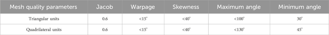
Table 1. Mesh quality parameters of finite element model.
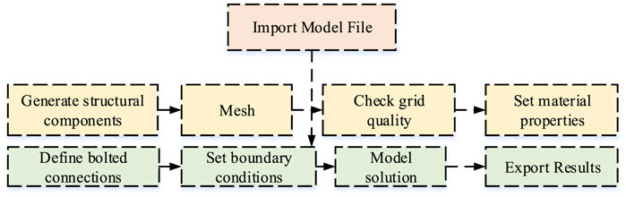
Figure 1. Flow chart for performance analysis of bolted overlap finite element model of 5G shared transmission tower angle steel connection.
3.2 Finite element model interface relationship, boundary conditions, and mesh generation scheme design
The mesh division is the primary step in the finite element model of bolt overlap for 5G shared transmission tower angle steel connections. Prior to this, it is necessary to establish a reference plane to ensure the uniformity and consistency of grid partitioning, thereby improving analysis accuracy. This study selected an equally large grid to minimize the overlap between the angle steel connection nodes and the main tower nodes, ensuring smooth calculation. By selecting the appropriate grid density, a balance between model computational efficiency and accuracy can be achieved. The study referred to industry practices and determined the grid density (Song et al., 2021; Fang et al., 2021). The result of grid partitioning is shown in Figure 2.
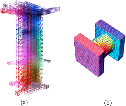
Figure 2. Grid division results of the finite element model for the overlap of angle steel connection bolts in 5G shared transmission tower. (a) Angle steel and iron tower. (b) Bolt and angle steel.
The key interface relationships in this research model include angle steel and tower body, bolts and angle steel and tower body, etc. The simulation of these contact relationships needs to consider the contact characteristics and force transmission methods under actual force conditions. In the finite element software ABAQUS, “face to face contact” is used to simulate these force relationships. The interaction between contact surfaces is achieved through the orthogonal and tangent properties of the contact surfaces. In the normal direction of the contact surface between the angle steel and the main body of the tower, “hard contact” is used to describe the contact relationship between the angle steel and the main body of the tower. The Coulomb friction model is used to describe and calculate the frictional force in the contact relationship between bolts, angle steel, and the main body of the iron tower. According to the provisions of GB 50017-2017 on the anti slip coefficient of Q345 steel, the Coulomb friction coefficient is taken as 0.35. The setting of boundary conditions simulates the actual force conditions. In the model, a rigid rod is used to simulate the loading beam, and one end is subjected to a horizontal displacement to simulate the actual torsional loading conditions.
Through the above settings, a bolt lap finite element model of the 5G shared transmission tower angle steel connection that can accurately simulate the actual situation is obtained. In the model, Q345 steel material is used for the experiment. Boundary conditions and contact relationship: The angle steel and the main body of the iron tower have “hard contact,” while the bolts, angle steel, and main body use the Coulomb friction model. Due to the type of steel and lack of galvanizing, according to the GB 50017–2017 standard, the Coulomb friction coefficient is taken as 0.32. The finite element single solid element type adopts SOLID95 element, which is suitable for three-dimensional solid simulation considering material and geometric nonlinearity. The reinforcement model adopts a bilinear isotropic reinforcement model, and the slope of the line in the reinforcement stage is 0.03E. Bolt connections are installed at the interface between the iron tower and the angle steel to ensure that the iron tower fully participates in the anti-torsion. In the model, the section connecting the iron tower and angle steel is simplified, only considering the bolted connection section. Meanwhile, consolidation constraints are set at the bolted connections to simulate the actual situation. To simplify the calculation, the model uses a rigid rod to simulate the loading beam. The rod’s length and placement are consistent with those of the loading beam in the static test. The loading beam is made of high-strength alloy steel, with a length of L = 1,420 mm and a diameter of 50 mm. One end is coupled to the column top through a hinged joint, and the other end is connected to an actuator to apply displacement load. Boundary condition setting: The angle steel tower body is in normal “hard contact”, and the axial pressure simulates the self weight of the tower body (200 kN constant). In the model, it is necessary to couple one end of the rigid rod with the surface of the tower and apply horizontal displacement at the other end. In this way, the finite element model can simulate the bending and torsional loading force of the specimen in static experiments, as shown in Figure 3.
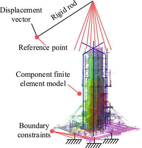
Figure 3. Boundary conditions of the finite element model under bending and torsion loading.
By adjusting the material characteristic parameters, model, and interface relationship parameters based on the finite element model of 5G shared transmission tower angle steel connection, a finite element model suitable for different scenarios can be obtained.
3.3 Bolt overlap design for angle steel connections of 5G shared transmission towers
The application of finite element analysis software in the research of bolt lap design of 5G common transmission tower angle steel connections has important practical significance. This design is a design approach that mainly considers the load and connection method, with the aim of ensuring the structural safety of transmission towers, reducing the stress and property damage on the tower body. In finite element analysis, the material characteristic parameters of angle steel and bolts are important considerations, which can simulate the response of angle steel and bolts under load and provide various design parameters. Among them, the stability, compressive strength, and tensile strength of angle steel and bolts are key calculation parameters (Gazman, 2023). The bolt overlap design process based on 5G shared transmission tower angle steel connection is shown in Figure 4.
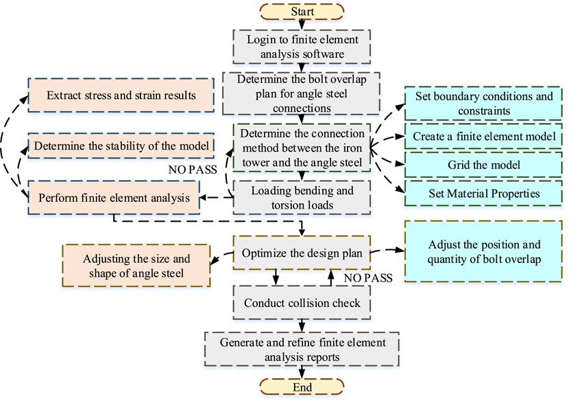
Figure 4. Design process for bolt overlap based on 5G shared transmission tower angle steel connection.
In Figure 4, the design process mainly consists of five steps. Firstly, the geometric modeling of the transmission tower structure needs to establish basic information such as spatial configuration, connection conditions, material properties, etc., to provide a prerequisite for subsequent finite element analysis. Second, it sets load parameters, and based on actual needs and working conditions, sets the size and distribution of loads as inputs for subsequent finite element analysis. Then, through finite element analysis software, the response of the iron tower structure under simulated load loading is obtained, including the stress and displacement of each part of the structure. Next, based on the analysis results, it evaluates the stability and safety of the structure and determines whether it meets the requirements of relevant design specifications. Finally, if the evaluation results do not meet the requirements, it is necessary to design optimization based on the analysis results. This is to improve the stability and safety of transmission towers.
When designing the lap joint of angle steel connecting bolts, it is necessary to calculate the load-bearing capacity of the angle steel and bolts, which will serve as the basis for the finite element analysis of the load response of the tower. The calculation formula is shown in Equation 5.
In Equation 5,
4 Finite element model analysis of bolt overlap for 5G shared transmission tower angle steel connection
The lap strength of angle steel connecting bolts is affected by factors such as material and geometric structure. Moreover, its strength directly affects the bearing capacity of the component. It also provides theoretical basis for optimizing the lap structure of angle steel connecting bolts. A systematic analysis is conducted on the performance of the bolt lap finite element model based on the 5G shared transmission tower angle steel connection. Then finite element model discussed in detail the structural characteristics and performance parameters of the model to enhance finite element model practical application value.
4.1 Influence of overlapping form of angle steel connection bolts on the bearing capacity of components
On the basis of completing the finite element analysis of the lap strength of angle steel connection bolts in 5G shared transmission towers, the next step will further explore the influence of the lap strength of angle steel connection bolts on the load-bearing capacity of the components themselves. In the previous analysis, it is learned that bolt overlap strength, as the core element of the joint, will directly affect the material’s load carrying capacity. Therefore, the next step is to conduct material fatigue tests to verify the influence of bolt overlap strength of various angle steel joints on material fatigue. Three types of angle steel connections are established in the study, including traditional angle steel connections, reinforced angle steel connections, and optimized angle steel connections. The traditional angle steel connection uses the standard method of overlapping angle steel and securing it with bolts, without requiring additional reinforcement. Reinforced angle connections are used to improve the strength of the connection by increasing the number of bolts, optimizing the bolt layout, or locally thickening the angle. Based on the reinforcement foundation, the angle connection is systematically optimized by combining finite element models and physical experiments. Among them, 31 types of angle steels are selected for experiments, including aluminum alloys, galvanized alloys, and so on. The finite element parameters are set as follows: Grid convergence is controlled using the Jacobian matrix (Jacobian ratio ≥0.6). The element type is a SOLID95 eight-node hexahedral element, which is suitable for the nonlinear analysis of Q345 steel materials. The grid density has been validated for sensitivity. When the element size is 20 mm or less, the stress solution oscillation amplitude is less than 2%. Finally, the key area is selected with an encrypted size of 15 mm and the non key area is 25 mm. The finite element solver uses the ABAQUS/Explicit solver. The time integration uses an explicit, centered difference method with a step-size control of 1 × 10⁻⁶ s. Next, the study will analyze the relationship between the tower connection forms of different angle steel connection bolts and the bearing capacity of the components, as shown in Figure 5.
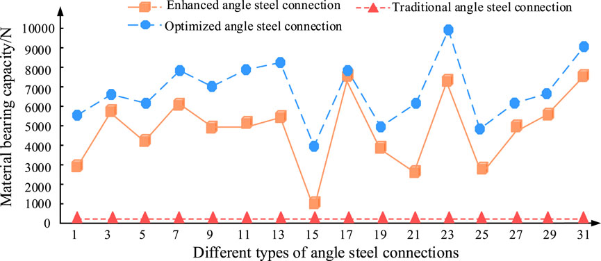
Figure 5. The influence of overlapping forms of different angle steel connection bolts on the bearing capacity of components.
Figure 5 shows that the strength of the tower joint refers to the maximum load capacity that the joint can withstand under stress. This is usually used to describe the mechanical properties of fasteners, such as welding, riveting, or bonding. According to the results shown in the figure, the optimized angle steel joint bolt has a higher component bearing capacity. Its average result is 7,900 kN, which is higher than the traditional 2,000 kN and the reinforced 5,800 kN. The main reason why the optimized design of angle steel joint bolt components has a stronger bearing capacity is that the research adopts a multi bolt collaborative arrangement and local thickening strategy, which effectively disperses stress concentration and improves the yield strength of the material. This result indicates that the optimization scheme can improve the mechanical properties of materials. Next, the study continued to analyze the optimal bearing capacity results under different bolt overlap strengths, as shown in Figure 6.
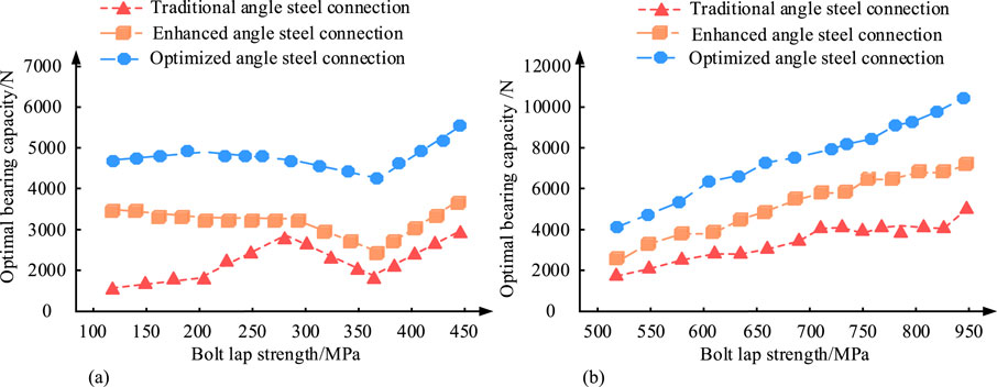
Figure 6. Optimal bearing capacity results under different bolt lap joint strengths. (a) Bearing capacity results of different angle steel connection schemes under low bolt overlap strength. (b) Bearing capacity results of different angle steel connection schemes under high bolt overlap strength.
Figure 6 shows the optimum load-bearing capacity results under different bolt overlap strengths. According to the test results, there is a certain correlation between the bolt overlap strength and the load-bearing capacity of the three steel angle connection schemes. When the bolt overlap strength is high, such as when the bolt overlap strength is above 500 Mpa, the load-bearing capacity of the steel angle connection corresponding to the scheme increases with the increase of the bolt overlap strength. Further finite element analysis shows the influence of bolt overlap strength on the mechanical properties of 5G tower steel angle connections. As the overlap strength increases from 100 MPa to 500 MPa, the torsional load capacity of the angle steel connections does not increase significantly at low overlap strengths. However, there is a significant increase in torsional load capacity at high overlap strengths. In addition, when the torsion angle is large, the connection undergoes inelastic deformation, such as when the bolt overlap strength is 360 Mpa, all three methods show deformation. Through a comprehensive comparison, it is found that the optimized scheme has a stronger bearing capacity compared to the reinforced and traditional schemes. It indicates that the mechanical properties of the material are better under the optimized scheme. From this, it can be seen that the steel connection scheme has a non-linear growth trend, that is, at lower bolt overlap strengths such as 500 MPa, the bearing capacity of all three schemes slowly increases with the increase of bolt overlap strength. When it exceeds 500 MPa, the bearing capacity of all three methods is significantly improved, and the optimized scheme performs the best, indicating that the mechanical properties of the material under the optimized scheme are better. The torsion angle and torque corresponding to different bolt tower connection strengths are different, as shown in Table 2 for details.
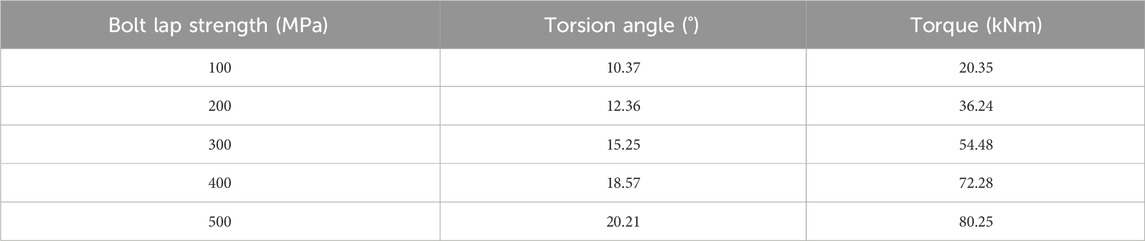
Table 2. Effect of bolt lapping strength on the torsion resistance of angle steel connections.
Table 2 shows the effect of bolt overlap strength on the torsional behavior of steel angle joints. According to the data in the table, as the bolt overlap strength increases, the corresponding torsion angle and torque also increase. When the bolt overlap strength is 500 Mpa, the corresponding torsion angle is 20.21° and the torque is 80.25 kNm. In addition, further analysis is conducted on the influence of bolt overlap strength on the bending capacity of angle steel connections, as shown in Table 3.
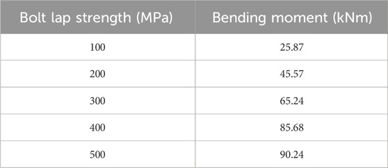
Table 3. Effect of bolt lapping strength on the bending resistance of angle steel connections.
According to the results in Table 3, the variation pattern of the flexural load-bearing capacity of steel angle joints is approximately the same as the variation pattern of the torsional load-bearing capacity of steel angle joints. Among them, the larger the bolt overlap strength, the larger the corresponding bending moment. However, when the bolt overlap strength increased from 100 MPa to 300 MPa in the early stage, the corresponding bending moment increased from 25.87 kNm to 65.24 kNm, with a significant increase. After the increase of bolt overlap strength exceeds 300 MPa, the increase of bending moment slows down.
4.2 Performance analysis of bolt lap finite element model based on 5G shared transmission tower angle steel connection
Next, a study is conducted on the influence of bolt overlap strength on the bearing capacity of the components themselves, and a finite element model of bolt overlap for the angle steel connection of 5G shared transmission towers is further analyzed. This model exhibits stability and safety under specific operating conditions. The optimized angle steel connection design shows significant advantages in improving bolt overlap strength and bearing capacity. The stress-strain ratio reflects a material’s Young’s modulus, which is a physical quantity that represents the material’s ability to resist deformation within the elastic range. The larger its value, the smaller the degree of deformation of the material when subjected to external forces. To measure the stress-strain ratio, strain gauges, and displacement gauges must be installed in the angle steel joints of the power tower. Then, according to Hooke’s law, the measured stress (calculated by load) and strain data are used, and the operating conditions are analyzed by a finite element model. The stress-strain results under working conditions are shown in Figure 7.
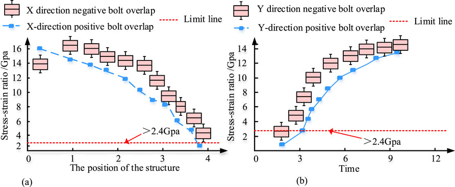
Figure 7. Stress and strain results of the bolted overlap finite element model for the angle steel connection of 5G shared transmission tower under various operating conditions. (a) Stress strain ratio of bolt overlap under various working conditions. (b) Stress-strain ratio of each working condition over time.
In Figure 7, the experiment selects 5 positions from the inside to the outside for bolt overlap and conducts stress-strain ratio analysis from 0:00 a.m. to 12:00 noon. In the angle steel connection of 5G transmission towers, stress-strain is an important parameter for evaluating structural stability. These parameters can predict the possible behavior and stability of transmission towers under various working conditions. According to the relevant “Design Specification for Transmission Towers,” for 5G shared transmission towers, the maximum stress-strain coefficient of the bolt overlap of angle steel connections should be 0.12. Meanwhile, the stress-strain ratio of bolt overlap, i.e., the ratio of stress to strain, should not be less than 2.4 Gpa. According to the results in Figure 7a, the stress-strain ratio gradually decreases as the structural position expands in the X direction, but all are greater than 2.4 Gpa. According to this, the material has high stiffness, which means strong elastic deformation resistance. This indicates that under optimized design, the deformation of the structure can be controlled (with small strain) under wind load and other working conditions, avoiding plastic failure and meeting the stability requirements of the iron tower. In Figure 7b, as time increases, the stress-strain ratio at each position under the Y-direction condition gradually increases, and all are greater than 2.4 Gpa, meeting the requirements of the tower design specifications. The maximum displacement and maximum stress distribution diagram of its bolt overlap is shown in Figure 8.
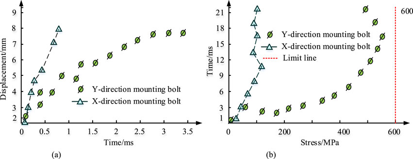
Figure 8. Schematic diagram of maximum displacement and maximum stress distribution for bolt overlap. (a) Maximum displacement diagram. (b) Maximum stress diagram.
Figure 8 shows that maximum displacement and maximum stress are two important indicators for the stability and safety of bolt overlap. Figure 8a is the maximum displacement value that increases with time under peak wind load conditions. The data shows that the maximum overlap displacement of the bolt is 8.67 mm, occurring in the X-axis, while the maximum displacement value in the Y-axis is 8.54 mm. According to the limit value of GB50017-2017 specification (standard ≤12 mm), it indicates that the optimized angle steel connection has not undergone instability or plastic deformation under extreme wind loads, meeting the requirements of structural elastic deformation. Figure 8b shows the maximum stress situation at the connection point of the model under the change of visibility, and the maximum stress in the Y direction is 582 MPa, indicating that the research design fully utilizes the plastic properties of the material while retaining about 20% safety margin. That is, the maximum stress of the reinforced Q345 steel can reach 630 MPa, which is within an acceptable range and meets the requirements of relevant specifications. The distribution of material strength is shown in Figure 9.
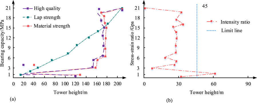
Figure 9. Partial results of material strength, lap strength, bearing capacity and strength ratio. (a) Material strength, lap strength, and bearing capacity distribution curve. (b) Strength ratio distribution curve.
In the analysis of bolt overlap in Figure 9, the measurement and control of parameters such as material strength, overlap strength, bearing capacity and strength ratio are important criteria for evaluating the stability and safety of the structure. In Figure 9a shows the relationship between the height of the tower and its bearing capacity. According to the curve in the figure, as the height of the iron tower increases from 20 m to 160 m, the material strength and mass show an increase. The main reason is that the material strength (yield strength of steel) increases due to the increase in the cross-section of the component. The bearing capacity gradually decreases with the height of the tower, mainly due to the prominent geometric nonlinear effect. Compared with lower height towers, the overall bearing capacity of high towers will decrease by about 10%. The overlap strength increases with the height of the tower. Among them, when the tower height is above 180 m, the material strength, tower joint strength, and other bearing capacities are maintained within the range of 17.87 MPa–19.98 MPa. Figure 9b shows the relationship between tower height and strength ratio. The strength ratio is mainly distributed in the range of 0 m–30 m for tower height, while for tower height above 45 m, the overall strength ratio is lower, maintaining a strength ratio of 0 Gpa to 2 Gpa. Further analysis reveals that in high towers greater than 45 m, the strength ratio drops to 0–2 GPa, indicating that the structural turning flexibility control (geometric nonlinearity enhancement) needs to focus on suppressing wind-induced vibrations. The thermal effect analysis of the finite element model is shown in Figure 10.
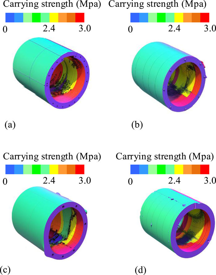
Figure 10. Thermal effect analysis of finite element model. (a) Positive thermal effect diagram. (b) Negative thermal effect diagram. (c) High altitude thermal effect diagram. (d) Low heat effect diagram.
Figures 10a–d show the positive thermal effect map, negative thermal effect map, high-altitude thermal effect map, and low thermal effect map, respectively. The lap strength of the bolt is a key factor affecting its stability and lifespan, and this microscopic characteristic has received widespread attention. In the positive heating effect diagram of Figure 10a, observing the bolts, it is found that the lap strength distributed radially from the center to the periphery of the bolts. The maximum lap strength of the bolt occurs at the central axis of the bolt, approximately 2.5 MPa. This result indicates that the main load transmission core area here (bearing more than 60% of mechanical stress) conforms to the axial force transmission theory of bolted connections. As the distance from the central axis increases, the lap strength gradually decreases, reaching the outer wall position of the bolt, and the lap strength drops to 0.8 MPa. This result reflects the stress diffusion effect and verifies the accuracy of the Coulomb friction model (μ = 0.35). In the negative thermal effect diagram of Figure 10b, observing the bolt from the opposite side, the overlapping strength also shows a radial distribution around the bolt’s central axis, but the strength gradient is more pronounced than before. At the central axis, the lap strength of the bolt can reach 2.7 MPa, while at the outer wall of the bolt, the lap strength decreases to 0.7 MPa. This result reveals uneven contact surface pressure, which may be due to manufacturing tolerances or installation deviations, and local micro motion wear risks need to be monitored. In the analysis of the high-altitude thermal effect diagram and low thermal effect diagram in Figures 10c,d, the strength at all positions is less than 345 MPa of the yield strength of Q345 steel, proving that the design meets the elastic safety criteria. The study is finally conducted using a finite element model to quantitatively analyze the performance of the lap joint of angle steel connection bolts for 5G shared transmission towers. Multiple disaster coupling tests are conducted to simulate actual working conditions. Seismic condition: El Centro waves with 0.3 g PGA are input and loaded in stages from 0.1% to 1.0% depending on the interstory displacement angle, with boundary conditions for fixed connections at the base of the columns and semi-rigid constraints at the angle nodes. Strong wind condition: CFD generates a fluctuating wind field with a peak wind pressure of 1.5 kPa and a turbulence intensity of 15%. Icing condition: The equivalent ice thickness is 30 mm, the density is 900 kg/m3, and the ice is subjected to 24-h freeze-thaw cycles in a low-temperature cabin at −15°C ± 2°C. Long term stability: Through 3 million high-frequency cyclic loads and synchronous salt spray of 5% NaCl solution to accelerate simulation for 30 years of service, the pre tightening force attenuation rate is monitored in real-time by piezoelectric sensors. Among them, earthquakes shall comply with GB 50011-2010. Wind load is equivalent to ASCE 7-22 wind tunnel. According to the IEEE 738 standard for icing, the critical value for bolted connections is set at 1.5 to distinguish between shear failure and net section failure modes. The test results of the overlap performance of angle steel connection bolts under multiple disaster scenarios are shown in Table 4.
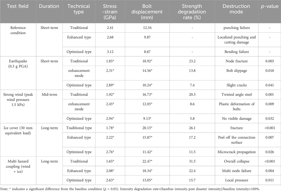
Table 4. Test results of overlapping performance of angle steel connection bolts in multiple disaster scenarios.
According to Table 4, seismic loads cause a 23.2% decrease in stress in traditional nodes, which is primarily manifested as a shift from shear failure to brittle fracture. This is due to the seismic dynamic amplification effect, which causes the loss of bolt preload force and leads to contact surface slip. The optimized scheme controls displacement at 10.24 mm (below the 12 mm specification limit) by adding bolt shear elements and thickening the end-plate design. This changes the failure mode to ductile bending. In strong wind scenarios, the strength degradation rate of the optimized scheme is only 5.8%, significantly lower than that of the traditional scheme (20.3%). Moreover, the stiffening rib design of the angle steel flange reduces the stress concentration factor from 3.2 to 1.8, avoiding local buckling. This result validates the applicability of Chen Fubo’s typhoon load theory. Over the long term, the strength of traditional type nodes degrades by 26.1% due to low-temperature brittleness and ice load cycling. The optimized scheme uses Q420 high-strength steel, which has an impact energy of 54 J at −40°C. This suppresses low-temperature crack propagation and reduces displacement by 43.3%. In extreme wind ice coupling disasters, the optimized type still maintains a stress-strain ratio of 2.63 GPa (higher than the lower limit of 2.4 GPa in the specification). Finally, in the analysis of long-term stability and degradation laws, the optimized type still exceeds the design value by 115% at 25 years, meeting the durability requirements of GB 50135-2019. In addition, ANOVA statistical tests shows that disaster type has the most significant impact on displacement (F = 38.72, p < 0.001), followed by technical type (F = 29.15, p < 0.001). The Tukey HSD test of the optimized model in various earthquake conditions rejects the null hypothesis (p < 0.05), indicating that it has good performance advantages. In addition, the study introduces multi-source data cross validation to verify the experimental analysis results. The results are shown in Table 5.
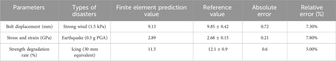
Table 5. Cross validation of multi-source data.
Table 5 shows the cross-validation results of the multi-source data. In the bolt displacement inspection, the predicted value (9.13 mm) under strong wind conditions is slightly lower than the mean of the experiments (9.85 mm). The error occurred due to the incomplete simulation of the transient effects of turbulent flow in the wind field. In stress-strain testing, the reference value for seismic conditions is 2.89. The predicted value is also 2.89. The absolute error range is 0.21, which meets the requirements. In terms of the strength degradation rate, the error in the icing condition is only 5.0%. This indicates that the low-temperature material brittleness model is highly accurate (refer to the Johnson-Cook constitutive model).
5 Conclusion
In the context of the rapid development of 5G communication networks, transmission towers, as an important physical carrier, their structural stability and security are particularly critical. Among them, the bolt lap strength of angle steel connections directly affects the bearing capacity of transmission towers. The research aimed to explore the relationship between bolt lap strength and angle steel connection bearing capacity through finite element modeling, providing a basis for the design of transmission towers. It used a finite element model to simulate angle steel connections under different bolt lap strengths to understand their impact on bearing capacity. As a result, it was found that the fluctuation of bearing capacity increased when the overlap strength of bolts was increased. The optimized angle steel connection had the highest bearing capacity and was significantly better than other schemes. In addition, the stress-strain ratio of bolt overlap, i.e., the ratio of stress to strain, should not be less than 2.4 Gpa. Meanwhile, in the analysis of the maximum stress distribution of bolt overlap, the experimental results showed that the maximum stress at the bolt overlap joint was 582 MPa, which met the requirements of relevant specifications. The research provides a new theoretical basis and technical support for the design and construction of 5G shared transmission towers. However, this study also has some limitations, including limitations in model simplification and assumptions. In practical engineering, node connections are typically semi-rigid, while in models, they may be simplified as rigid connections. This results in discrepancies between actual force transmission and theoretical calculations. In addition, due to the uncertainty of long-term performance, although the optimized bolt overlap performs well in short-term tests, the fatigue performance and corrosion effects in long-term service have not been fully investigated. Engineering practice suggestion: Strengthen the design of weak areas. Tower leg components are the weak points of transmission towers. It is recommended to focus on their load-bearing role in the design and to use reinforcing measures (such as box section reinforcement) to improve their load-bearing capacity. For towers over 180 m, it is recommended to increase the redundancy design of material strength and lap strength. Furthermore, the optimization of node connection design to enhance its longevity is imperative. This can be achieved by incorporating semi-rigid characteristics into node connections to circumvent errors stemming from oversimplified assumptions. Future research endeavors should prioritize the investigation of the repercussions of extreme weather conditions, such as intense winds and ice disasters, on transmission towers. Concurrently, the evaluation of the long-term service performance of materials must be strengthened. This includes studying the fatigue performance and corrosion effects of bolt overlap during long-term service, establishing a long-term monitoring system, evaluating the health status of structures, and improving the application effect of technology.
Data availability statement
The original contributions presented in the study are included in the article/supplementary material, further inquiries can be directed to the corresponding author.
Author contributions
WX: Conceptualization, Funding acquisition, Methodology, Writing – original draft. YH: Data curation, Investigation, Writing – original draft. YD: Software, Supervision, Writing – original draft. NZ: Writing – review and editing. TT: Resources, Visualization, Writing – review and editing.
Funding
The author(s) declare that financial support was received for the research and/or publication of this article. The research is supported by Science and Technology Project of State Grid Jiangsu Electric Power Co., Ltd. (No. J2021022): Transformation Optimization Design and Modular Construction Research on the New Base Stations of Shared Towers.
Conflict of interest
Authors WX, YH, YD, and NZ were employed by Economic Research Institute Grid Jiangsu Electric Power Co., Ltd.
The remaining author declares that the research was conducted in the absence of any commercial or financial relationships that could be construed as a potential conflict of interest.
Generative AI statement
The author(s) declare that no Generative AI was used in the creation of this manuscript.
Publisher’s note
All claims expressed in this article are solely those of the authors and do not necessarily represent those of their affiliated organizations, or those of the publisher, the editors and the reviewers. Any product that may be evaluated in this article, or claim that may be made by its manufacturer, is not guaranteed or endorsed by the publisher.
References
Cahyono, H. S., Mulyono, J., Wicaksono, M. H., and Hendy Wicaksono, M. (2024). Upper–structure analysis of bts tower on high wind speed area. DEARSIP J. Archit. Civ. 4 (02), 119–133. doi:10.52166/dearsip.v4i02.7800
Eom, T. S., Cho, S. R., and Lim, J. J. (2022). Behavior of end plate connection for steel angles. Eng. Struct. 252 (2), 113714–14. doi:10.1016/j.engstruct.2021.113714
Eom, T. S., Lim, J. J., and Kim, J. W. (2021). Axial compressive behavior of concrete-encased high-strength steel angle columns. J. Struct. Eng. 147 (4), 2–11. doi:10.1061/(asce)st.1943-541x.0002908
Fang, Z., Liang, W., Fang, H., Jiang, H., and Wang, S. (2021). Experimental investigation on shear behavior of high-strength friction-grip bolt shear connectors in steel-precast UHPC composite structures subjected to static loading. Eng. Struct. 244 (1), 112777–15. doi:10.1016/j.engstruct.2021.112777
Gao, Y., Wang, J., and Liu, Y. (2021). Interfacial fracture toughness measurement of welded babbitt alloy SnSb11Cu6/20Steel. Fatigue and Fract. Eng. Mater. and Struct. 44 (7), 1837–1849. doi:10.1111/ffe.13466
Gazman, V. D. (2023). A new criterion for the ESG model. Green Low-Carbon Econ. 1 (1), 22–27. doi:10.47852/bonviewglce3202511
Jiang, K., and Zhao, O. (2022). Net section failure of S690 high-strength steel angle-to-plate connections. J. Struct. Eng. 148 (4), 1–13. doi:10.1061/(asce)st.1943-541x.0003322
Ke, K., Zhang, M., Yam, M. C. H., Lam, A. C. C., Wang, J., and Jiang, B. (2022). Block shear performance of double-line bolted S690 steel angles under uniaxial tension. Thin-Walled Struct. 171 (2), 108668–19. doi:10.1016/j.tws.2021.108668
Kim, H., Park, A., and Hwang, J. H. (2022). Cyclic lateral loading test for composite columns with high trend steel angle cage. Eng. Struct. 250 (1), 2–17. doi:10.1016/j.esttruct.2021.113463
Lashgari, H. R., and Zangeneh, S. (2024). Numerical and experimental failure analysis of steel components in a high-voltage transmission tower structure. J. Fail. Analysis Prev. 24 (3), 1030–1045. doi:10.1007/s11668-024-01920-y
Liang, Y., Zhao, C. X., Wei, Y. Y., Tong, M. N., Feng, H. Q., and Dong, X. S. (2025). Fragility analysis of an ultra high voltage transmission tower in saline soil subjected to wind loads. Struct. Infrastructure Eng. 21 (5), 845–862. doi:10.1080/15732479.2023.2246433
Meng, X., Chen, W., Mei, H., and Wang, L. (2023). Corrosion mechanism of UHV transmission line tower foot in Southern China. IEEE Trans. Power Deliv. 39 (1), 210–219. doi:10.1109/tpwrd.2023.3329140
Rong, C., Shi, Q., and Wang, B. (2021). Seismic performance of angle steel frame confined concrete columns: experiments and FEA model. Eng. Struct. 235 (14), 111983–18. doi:10.1016/j.engstruct.2021.111983
Shu, Z., Ning, B., Chen, J., Li, Z., He, M., Luo, J., et al. (2023). Reinforced moment-resisting glulam bolted connection with coupled long steel rod with screwheads for modern timber frame structures. Earthq. Eng. and Struct. Dyn. 52 (4), 845–864. doi:10.1002/eqe.3789
Song, H. Y., Wang, Y. P., Esling, C., Wang, G. D., and Liu, H. T. (2021). The role of grain colony on secondary recrystallization in grain-oriented electrical steel: new insights from an original tracking experiment. Acta Mater. 206 (1), 116611–611. doi:10.1016/j.actamat.2020.116611
Wang, B., Nishiyama, M., Zhu, S., Tani, M., and Jiang, H. (2021). Development of novel self-centering steel coupling beams without beam elongation for earthquake resilience. Eng. Struct. 232 (3), 111827–13. doi:10.1016/j.engstruct.2020.111827
Wu, H., Chang, H., and Tian, X. (2023). Trajectory planning method for UAV inspection of transmission towers based on simulated annealing algorithm. J. Electron. Inf. Sci. 8 (5), 52–57. doi:10.23977/jeis.2023.080508
Zhang, L., Ren, Y., Zhou, X., Shen, G., Tu, Z., and Yao, J. (2023b). Wind-induced responses of corroded angle-steel transmission tower. Energies 16 (14), 5429. doi:10.3390/en16145429
Zhang, Y., Yang, Z., Li, Y., Cheng, X., and Huang, Z. (2023a). Experimental and theoretical investigation of self-tapping bolt core tube flange column connection of prefabricated steel structure. Eng. Struct. 278 (1), 115482–18. doi:10.1016/j.engstruct.2022.115482
Keywords: 5G, iron towers, bolt, shared transmission, finite element model, angle steel
Citation: Xu W, Hu Y, Dai Y, Zhang N and Tong T (2025) Finite element model analysis of bolt overlap for angle steel connections of 5G shared transmission towers. Front. Mech. Eng. 11:1584991. doi: 10.3389/fmech.2025.1584991
Received: 28 February 2025; Accepted: 07 July 2025;
Published: 18 July 2025.
Edited by:
Hamid Reza Karimi, Polytechnic University of Milan, ItalyReviewed by:
Abdelmoumen Anis Bousahla, University of Sidi-Bel-Abbès, AlgeriaYilan Miao, University of Michigan, United States
Copyright © 2025 Xu, Hu, Dai, Zhang and Tong. This is an open-access article distributed under the terms of the Creative Commons Attribution License (CC BY). The use, distribution or reproduction in other forums is permitted, provided the original author(s) and the copyright owner(s) are credited and that the original publication in this journal is cited, in accordance with accepted academic practice. No use, distribution or reproduction is permitted which does not comply with these terms.
*Correspondence: Teng Tong, eHd6MjAyMzA1QDEyNi5jb20=