 Shengli Yang1,2
 Hao Yue
 Ruihao Zhai
- 1State Key Laboratory of Water Resource Protection and Utilization in Coal Mining, Beijing, China
- 2School of Energy and Mining Engineering, China University of Mining and Technology-Beijing, Beijing, China
- 3Department of Numerical Control Engineering, Shanxi Institute of Mechanical and Electrical Engineering, Changzhi, China
With the increasing depth and intensity of coal mining, there is an increasing risk to the working face due to high static load and periodic breakage of the roof. The relation between the support and the surrounding rock under static–dynamic coupling loading disturbance is an important factor affecting the stability of the working face. In this study, a 3D physical modeling platform is developed to study the interaction between the shield and strata under dynamic and static disturbance. In the experiment, the static load is set to 0, 0.5, 1, and 2 MPa, respectively. The different dynamic load is realized by changing the fall height of the iron plate. The change in hydraulic support resistance is recorded by the pressure monitoring system. The displacement of the coal wall is monitored by using an infrared rangefinder. The results show that the change in static load and dynamic load will affect the support resistance and coal wall displacement. With the increase in dynamic load, coal wall displacement, and bracket resistance increase, the increase is not linear. The larger the dynamic load, the greater the increase. Static load change has little effect on bracket resistance, and the impact on coal wall displacement is large. With the increase in static load, coal wall displacement is reduced and then increased. In static load, for the stability of coal wall, there is a threshold; below the threshold, the static load can improve the stability of coal wall, exceed the threshold, but accelerate the destruction of coal wall. At the same time, the stability coefficient of the quarry bracket and surrounding rock is defined. The sensitivity analysis of the main parameters is carried out. The method of controlling the stability of the quarry bracket and surrounding rock is proposed.
Introduction and Background
The relationship between coal mine quarry supports and surrounding rock is an important part of mine pressure theory. With the rapid development of all areas of coal mining (Deng et al., 2020; Deng et al., 2022; Chen Jianhang et al., 2021; Chen Yulong et al., 2021), the understanding of the relationship between quarry supports and surrounding rock is also in-depth. The quarry support is an important part of the support system, and scholars at home and abroad have conducted research on different types of support systems. Shiroma et al. (2004) studied the standardization of tunnel support reduction patterns on the basis of the test construction results (Shiroma et al. (2004)). A strong support system was established suitable for a squeezing tunnel for the purpose of addressing problems exhibited in the extreme deformation of rock mass, structure crack, or even failure during the excavation phase (Wang et al., 2019). Zhang C analyzed and discussed stress characteristics and deformation patterns of the primary support and secondary lining structures, and reveals the influencing mechanisms of different tunneling modes on the stress characteristics of the support and lining structures (Zhang and Jiang, 2020). New methods and theories have been emerging. However, in the case of coal mines (Li, et al., 2019), the support system has also changed due to the influence of mining. It is well known that the force on the support of the quarry comes from the activity of the basic top and the direct top rock layer (Qian et al., 1994). It is known that the incoming pressure of the roof plays a key role in the mine roof accident. The key to the incoming pressure of the roof lies in the mutual coupling relationship between the breakage of the basic roof, the direct roof, the support, the coal body, and the bottom plate. Therefore, it is of great significance to study the relationship between the bracket and the surrounding rock in the mining site for the safe and efficient production of coal mines.
For this topic, scholars have carried out a lot of research, supplementing and improving the traditional brace envelope relationship (Cao et al., 1998). The relationship between the working resistance of the stent and the amount of roof sinking has been studied from an energy perspective (Gao et al., 1999). An algorithm was proposed to consider the actual conditions of rock mass and support interaction and the algorithm implementation method to ensure efficient calculation of stresses in rock and support (Seryakov and Kurlenya, 2018). Two-dimensional (2D) continuum finite-element models of longwall panels were developed and analyzed to understand the interaction of hydraulic-powered support with surrounding rock strata (Verma and Deb, 2013). The influence of the three-dimensional stress on the surrounding rock supported with different stiffness was studied (Wu et al., 2016). Stress distribution laws of surrounding rock plastic zone of the tunnel, the mechanism of load-bearing and acting relation between surrounding rock and support were studied (Zhang et al., 2008). The study was conducted on the basis of traditional mining pressure theory. For different mining conditions, the correlation between the bubbling and flaking gang and the support parameters of large inclination isolated working face was studied (Xie et al., 2013). The relationship between the pressure pattern and the surrounding rock of the coal seam above 10 m and below 10 m was studied (Yan, 2013). The characteristics of the basic top rock layer breakage and the working resistance of the support when crossing the old void area were studied (Bi, 2015). A model of the relationship between the brace envelope of the upper thin and lower thick coal seam group and the brace envelope of the same mining was established (Lu et al., 2017). The support system when the working face was retrieved over the trap column was studied (Zhao, 2019). The mechanism of mine pressure and the mechanical relationship between the support and the surrounding rock at the 8.8 m super-high comprehensive mining face was analyzed (Yang, 2020; Xu, 2021). The relationship between the support and the surrounding rock under comprehensive mining in two directions was analyzed: direction and tendency. This provides experience and methods for the study of the bracket-rock relationship under different mining conditions, based on which scholars have conducted in-depth studies in different directions (Zhu, 2020). The relationship between the initial bracing force and the stability of the roof slab was studied (Wan et al., 2011). The “three-factor method” to consider the actual use effect of the bracket was proposed (Zhang et al., 2014). A binary criterion for determining the working resistance of the brace by balancing the roof load and maintaining the stability of the coal wall was established (Wang et al., 2014). The “single rock beam” and “double rock beam” structures were proposed (Wu et al., 2016). The method of moving the roof chaser with pressure rubbing was proposed (Yang et al., 2018). The preliminary method of determining the impact force was obtained (Yang et al., 2019). A technical idea of using the mining pressure of the working face to break the hard coal wall was proposed (Li et al., 2019). A “macro-large-small” structural mechanics model of the quarry overburden was established (Li et al., 2020). The relationship between the support rock and the surrounding rock in two qualitative and quantitative ways was demonstrated (Zhang et al., 2020).
However, most of the scholars have studied the relationship between the support and the surrounding rock at the working face based on the traditional static load conditions, the consideration of dynamic load is missing. In recent years some scholars have taken the dynamic load effect caused by the roof breakage into consideration in the study of the relationship between the support and the surrounding rock (Yang, 2019). However, most of the studies are only based on dynamic load conditions and do not meet the reality that dynamic and static loads exist simultaneously which are inseparable in the quarry. Therefore, in order to better fit the actual engineering situation, both must be considered when studying the bracket-rock relationship. On this basis, a similar simulation experiment platform that can simulate the relationship between the bracket and surrounding rock in the quarry under dynamic and static load conditions is developed. The relationship between the bracket and surrounding rock under dynamic and static load disturbance is further studied.
Model Development
Experimental Platform Development
The independently developed dynamic and static load similarity simulation platform can study the relationship between the quarry support and the surrounding rock under different static and dynamic load conditions. In this system, the platform mainly consists of five parts, namely static load application device, dynamic load application device, hydraulic support, experimental main frame body, and pressure monitoring system, as shown in Figure 1. The experimental platform’s length is 130 cm, width is 65 cm, and height is 90 cm. The mainframe of the platform is fitted with similar simulated materials as required. From the bottom to the top are the simulated coal wall and the direct roof, while the hydraulic support is installed in front of the coal wall. The coal body is generally made up of sand, lime, gypsum, and water in a certain ratio. The thickness of the coal body is 60 cm, the length is 65 cm and the width is 65 cm. The direct roof is made up of sand, lime, gypsum, water, and cement in a certain ratio. The thickness of the direct top is 45 cm, the length is 130 cm and the width is 65 cm. The hydraulic support consists of two hydraulic cylinders with a load capacity of 8 t. The static load application device consists of a hydraulic cylinder and a counterforce device, where the hydraulic cylinder has an ultimate load capacity of 8 t. The magnitude of the applied static load pressure is monitored and controlled by a pressure gauge with a range of 10 MPa. The dynamic load application device is a frame beam fixed with four electromagnets with extremely strong adsorption force on the iron plate, where the electromagnets can be adjusted by adjusting the space position to simulate different degrees of dynamic load impact effect. At the same time, the up and down movement of the electromagnets can better simulate the different amounts of delamination between the direct top and the basic top with an accuracy of up to 1 mm and a maximum movement distance of 20 cm. The left and right movement of the electromagnets on the track can better restore the location of the top plate breakage by changing the iron plates under different conditions. It is possible to simulate the different dynamic load effects of the overlying rock layer on the roof plate. The specific operation is: after the electromagnet is disconnected, the iron plate falls under the action of gravity to simulate the basic roof breakage. The pressure monitoring system consists of a load cell, a data relay base station, and a computerized acquisition unit with a data acquisition frequency of 50–100 Hz.
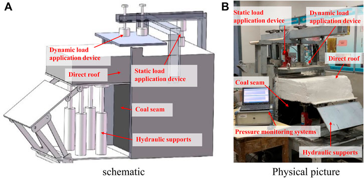
FIGURE 1. 3D physical modelling platform for the dynamic and static test.
Experimental Process
In this experiment, the relationship between the quarry support and the surrounding rock is simulated by the orthogonal design of multiple comparison experiments with different combinations of static and dynamic loads. Different static loads represent the original rock stresses of different coal mines, and different heights represent the strength of the impact on the working surface when the roof is broken. According to the similar scale and model size, the static load of 0.5–2 MPa can represent the static load of the field degree. The static loads are set at 0, 0.5, 1, and 2 MPa. Considering the feasibility and simplification of the experiment, the weight of the iron plate is 100 kg and the height range is set to 1–10 cm to represent the impact of the fundamental top fracture on the direct top. Table 1 shows the specific experimental program.
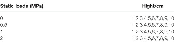
TABLE 1. Experimental program.
The iron plate is dropped from a height of 1–10 cm above the direct top under different static load conditions as follows. The material proportions have been determined by several tests and can be found in the literature (Yang et al., 2021).
1) Lay the simulated mock-up material, and mix well according to the ratio of sand, lime, and gypsum of 20:1:1. Add 7% of the weight of the well-mixed material with water, continue mixing well, lay it into the box, tamp the coal body simulated material using a tamping tool, and air-dry it for 3–5 days until the model is moderately dry.
2) Place hydraulic support and pressure monitoring system in front of the coal simulation material after it has air-dried.
3) Lay direct roof simulation material over the coal body simulation material and hydraulic supports in a ratio of 5:10:1:1 of sand, lime, gypsum, and cement, tamping with a tamping tool and air-drying for 3–5 days until the direct roof simulation material is moderately dry.
4) Application of the corresponding static load to the simulated material by means of a static load application device.
5) Attach the iron plate to the electromagnet and drop it from a height of 1–10 cm above the direct top.
6) The changes in hydraulic support resistance are recorded by a pressure monitoring system and the coal wall displacement is monitored by an infrared rangefinder.
Results and Analysis
Analysis of Experimental Phenomena
Figure 2 shows the damage of similar simulated materials during the experiments. These figures are all phenomena produced at 2 MPa and a fall height of 10 cm. (a) and (c) are phenomena after the 3rd shock. (b) and (d) are the phenomena of the 10th impact. (a) shows the coal wall just start to flake. The area of flaking is mainly concentrated in the upper part of the coal wall, accompanied by a small amount of damage in the lower part. The damage is mainly in the form of tensile cracking damage. (b) is a large area of the coal wall, mainly concentrated in the middle and upper part of the coal wall, with the same tensile cracking damage. Under the action of static load and impact load, the coal wall produced tensile stress greater than its tensile strength and finally produced tensile cracking damage. When the direct roof was subjected to a smaller impact, a fracture was produced as shown in Figure 2C, the length and width of the fracture were smaller. After the direct roof has been subjected to a larger impact, a fracture as shown in Figure 2D is produced and the entire direct roof is cut down along the coal wall. In the coal mine site, when the amount of inter-top delamination is small, the dynamic load is small, and the extent of damage to the coal wall and roof is small. As shown in Figures 2A,C, where the coal wall only produces a small area of sheeting and the roof fissures begin to develop slowly. When the amount of inter-roof departure is larger, the dynamic load is larger, and the damage to the coal wall and roof is greater. As shown in Figures 2B,D, where the coal wall starts to have large flake helpers and the roof plate produces large cracks or complete fractures.
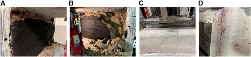
FIGURE 2. Diagram of the experimental process.
Development of Shield Loads
It was found that as the static load and the drop height of the iron plate changed, the brace resistance and coal wall displacement also changed. As shown in Figures 3, 4, with the increase in the height of the iron plate drop, the amount of offset between the top slab in the coal mine site, the coal wall displacement, and the resistance of the bracket keeps increasing. They are not linear. The larger the amount of offset, the larger the increase. Therefore, the core of the stability of the relationship between the bracket and the surrounding rock in the mining site is to control the amount of delamination between the basic top and the direct top. So that the amount of delamination between the top plates is as small as possible. The mine pressure will be relatively moderate when the pressure comes in the mining cycle. Figure 3 shows the working resistance of the hydraulic support under a static load of 0, 0.5, 1, and 2 MPa respectively. Through analysis, it is found that with the increase of static load, the working resistance of the hydraulic support is also increasing. However, the increase is not large, which means that the change of static load has little effect on the working resistance of the hydraulic support. This is mainly because the weight of the direct top and the impact force of the basic top on the direct top are borne by the hydraulic support and the coal body. The coal body bears most of the weight. The hydraulic support only bears a small part of the weight. So, when the static load increases, most of the energy is borne by the coal body, resulting in a significant increase in the displacement of the coal wall, and the phenomenon of the piece gang appears. The role of the hydraulic support is mainly to control the amount of departure between the direct top and the basic top, rather than to resist the weight of the overburden. For working faces with unstable coal walls, the stability of the coal wall should be controlled as much as possible so that the coal body in front of the working face can better bear the weight of the overburden.
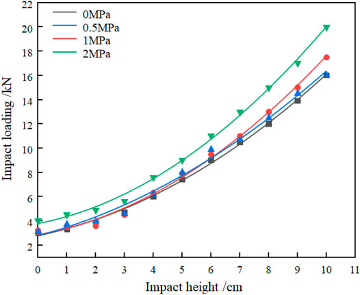
FIGURE 3. Impact forces at different heights.
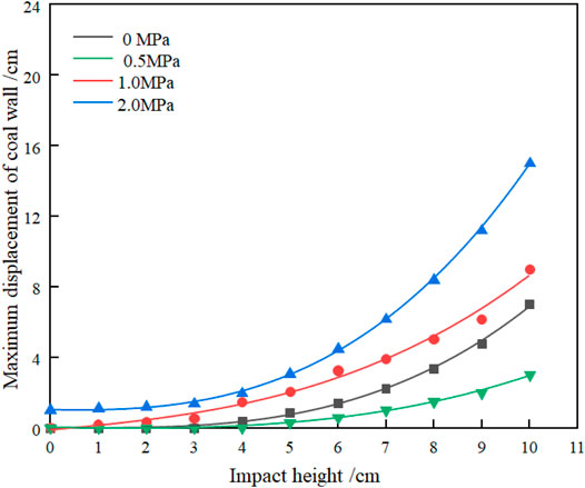
FIGURE 4. Coal wall displacement at different heights.
Development of Horizontal Displacement of the Coal Wall
Figure 4 shows the displacement of the coal wall under different static load conditions. According to the data in the figure, it can be found that, also at 10 cm impact height, the maximum displacement of the coal wall is about 7 cm without static load restraint. The maximum displacement of the coal wall is 3 cm with 0.5 MPa static load restraint. The maximum displacement is reduced by about 57%, which can be considered that a certain degree of static load can improve the stability of the coal wall. As the static load continues to increase, the maximum displacement of the coal wall rapidly increases to more than 8 cm, indicating that there is a threshold value for the promotion of the static load on the stability of the coal wall, below which the static load is beneficial to the stability of the coal wall, beyond which it will instead accelerate the sheeting of the coal wall, thus affecting the stability of the quarry support and the surrounding rock system. With the increase of static load, the change of coal wall displacement is more obvious than the hydraulic bracket working resistance. With the increase in the amount of offset, the displacement of the coal wall keeps increasing. The increase is not linear and greater under the condition of a large static load. It can be considered that the increase in static load does not have a significant impact on the working resistance of the hydraulic support, but has a greater impact on the displacement of the coal wall. So, the stability of the quarry support and the surrounding rock system can be controlled by increasing the resistance of the hydraulic support which is limited. The stability of the quarry support and the surrounding rock system should be studied from both the stability of the coal wall and the amount of delamination between the roof plates. The support force of the coal body should also be considered in the design and selection of the on-site hydraulic support.
Development of Stability Coefficient
From the previous analysis, the load on the quarry is borne by the coal wall and the bracket together. The source of the dynamic load is mainly due to the impact effect on the direct top caused by the breakage of the roof plate during the periodic incoming pressure. So, the stability of the bracket and the surrounding rock system of the quarry can be achieved by enhancing the ultimate bearing capacity of the coal wall or the maximum working resistance of the hydraulic bracket. The role of hydraulic support is to control the amount of separation between the basic roof and the direct roof. In the coal mine site, the initial support force of the hydraulic support can be increased to reduce the amount of separation between the roof slabs, thus reducing the amount of dynamic load impact caused by roof breakage.
The stability of the support and the surrounding rock depends on the ultimate bearing capacity of the coal wall and the maximum working resistance of the hydraulic support. The quarry support and surrounding rock system will become unstable when the sum of the ultimate bearing capacity of the coal wall and the maximum working resistance of the hydraulic support is less than the load given to the direct top by the weight of the basic top and the direct top. Therefore, the stability factor for the quarry bracket and the surrounding rock system is defined K as the ratio of the sum of the ultimate bearing force of the coal wall and the maximum working resistance of the hydraulic support to the load applied to the quarry.
where Qmax is the ultimate bearing force of the coal body, Fmax is the maximum working resistance of the hydraulic support, and Fc is the impact force on the direct roof after the basic roof destabilization (Yang et al., 2019) and Qz is the weight of the direct roof.The ultimate bearing capacity of the coal body Qmax is (Wang et al., 2014)
where G is the gravity of coal sliding body, α is the included Angle between shear surface and coal wall, φ is the Angle of internal friction of coal body, Q0 is the force of protective plate on coal wall, C is the cohesion of coal body, H2 is the failure height of coal wall. The specific parameters and position relationship can be referred to in Figure 5.
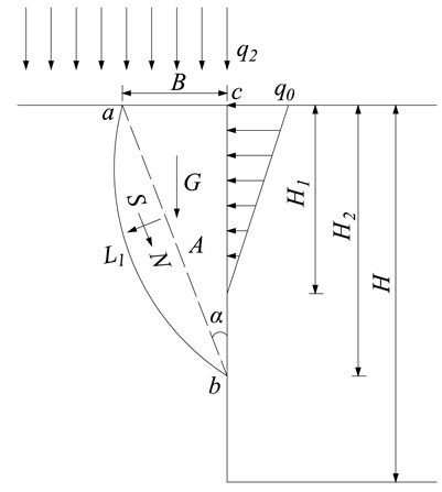
FIGURE 5. Shear failure model of coal wall (Kong et al., 2017).
Simplifying Fq. 2, as the force of the coal wall guard plate in the field has little effect on the coal wall, the calculation of Q0 will be ignored, and the following formula is obtained:
Because the impact force caused by slip instability is greater than the impact force caused by rotary deformation instability, Fc calculates the impact force according to the slip instability (Yang et al., 2019), and it is simplified to obtain Eq. 4. Let p =tan φ, and let n =EH1Lρ.
In Eqs. 4, t is the impact time after the basic roof is broken, m is the mass of the basic roof, Q is the overburden load of the basic roof, E is the elastic modulus of the basic roof, H1 is the thickness of the basic roof, L is the length of the basic roof block, ρ is the density of the basic roof, Δ is the off-layer volume, and g is the gravitational acceleration.
Substituting Eqs. 3, 4 into Eq. 1 for simplification, we obtain the following equation:
A sensitivity analysis of the stability coefficient K of the quarry bracket and the surrounding rock system was carried out according to Eq. 5. The parameters are assigned according to the actual situation on-site, as shown in Table 2.
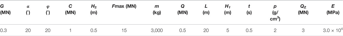
TABLE 2. Values for each parameter.
Figure 6 shows the effects of off-layer volume, maximum working resistance of the support, modulus of elasticity, and direct top weight on the stability of the quarry bracket and the surrounding rock system. As the off-layer volume increases (Figure 6A), the stability of the quarry stands and the surrounding rock system becomes worse. It is consistent with the derivation from the previous study, from which (Yang et al., 2019) it is also evident in this study that as the amount increases, F冲 increases significantly. This leads to greater loading of the quarry, and in turn, makes the quarry support and the surrounding rock system less stable. The increase in the maximum working resistance of the hydraulic support (Figure 6B) enhances the stability of the quarry bracket and the surrounding rock system. The increase is linear, but the maximum working resistance of the hydraulic support in the field is constrained by equipment and technology. It cannot be increased indefinitely, so the use of support to control the stability of the quarry bracket and the surrounding rock system is limited. The modulus of elasticity of the basic roof (Figure 6C) is positively correlated with the stability of the quarry bracket and the surrounding rock system. The increase in the modulus of elasticity makes the quarry more stable, but the increase is not linear. As the modulus of elasticity increases, the growth rate of the stability coefficient of the quarry bracket and the surrounding rock system gradually tends to level off. As the direct top weight increases (Figure 6D), the static load required on the support and coal body increases, making the quarry less stable and more prone to instability.
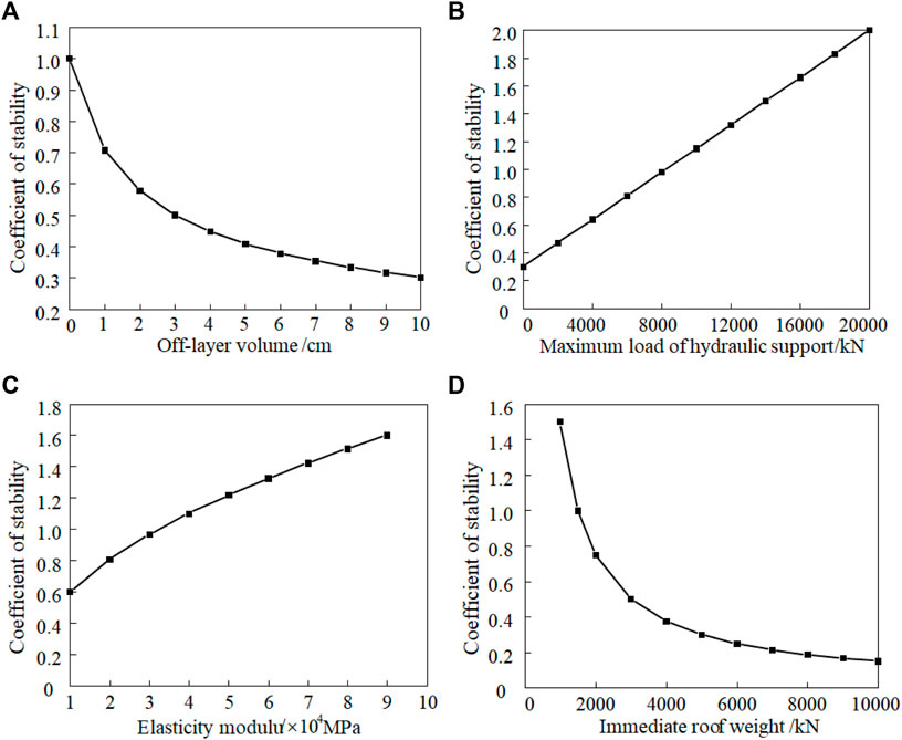
FIGURE 6. Effect of stability coefficients for each parameter.
The stability coefficient K indicates the stability degree of the quarry bracket and the surrounding rock system. When K is greater than 1, it indicates that the quarry bracket and the surrounding rock system are stable. The greater the value of K indicates that the quarry can bear the load the stronger the ability. When K is less than 1, it indicates that the quarry bracket and the surrounding rock system will be destabilized. The specific destabilization forms macroscopic performance, that is, the coal wall sheet gang, hydraulic bracket pressure frame, and inverted frame, the smaller the value of K indicates that the quarry can bear the load the weaker the ability. As can be seen from the above equation, in addition to improving the stability of the quarry bracket and the surrounding rock system can improve the ultimate bearing capacity of the coal body. It can also increase the maximum working resistance of the hydraulic bracket and reduce the load on the working face. For the coal wall, the ultimate bearing capacity of the coal body can be increased by means of “flexible reinforcement.” In working faces with unstable coal walls, increasing the stability of the coal wall is more effective in controlling the stability of the quarry bracket and the surrounding rock system than increasing the maximum working resistance of the hydraulic support. For the hydraulic bracket, raising the maximum working resistance as much as possible will play a certain role in promoting the quarry bracket and the surrounding rock system, but not fundamentally. The amount of separation between the roof plate should be reduced by raising the initial bracing force of the hydraulic bracket, to achieve the reduction of the dynamic load impact of the roof plate, which is the most effective measure to reduce the dynamic load effect of the quarry. Comprehensively, it can be considered that the core of controlling the stability of the quarry bracket and surrounding rock system is to improve the stability of the coal wall and reduce the amount of off-layer volume.
Conclusion
1) A similar simulation platform for dynamic and static loads has been developed, allowing the study of the relationship between the quarry support and the surrounding rock under simultaneous consideration of dynamic and static load disturbances, with different static load constraints and different drop heights set up for the experiments.
2) The core of the stability of the relationship between the bracket and the surrounding rock in the quarry is to control the amount of delamination between the basic top and the direct top so that the amount of delamination between the top plate is as small as possible or no delamination is produced.
3) The stability of the quarry bracket and the surrounding rock system is limited by increasing the resistance of the hydraulic bracket in the quarry, and it needs to be considered more from the stability of the coal wall and the amount of separation between the roof plates.
4) Define the stability coefficient K of the quarry bracket and the surrounding rock system. The amount of separation, the direct jacking weight, and the stope support are nonlinearly inversely related to the stability of the surrounding rock system. The maximum working resistance of the bracket is linearly positively correlated with the stability coefficient. The elastic mold is nonlinearly positively correlated with the stability coefficient.
Data Availability Statement
The original contributions presented in the study are included in the article/Supplementary Material, further inquiries can be directed to the corresponding author.
Author Contributions
SY provided the overall framework of the thesis. HY completed the physical experiment section. RZ and ZC analyzed experimental data. XW changed the formatting and images of the article. All authors contributed to manuscript revision and read and approved the submitted version.
Funding
This study was supported by the National Natural Science Foundation of China (51974320), Natural Science Foundation of Hebei (E2020402041), “State Key Laboratory of Coal Mining Water Conservation and Utilization” 2017 Open Fund Project Grant (SHJT-17-42.4), and the Science and Technology Innovation Project of China Energy Investment Corporation (SHJT-17-38).
Conflict of Interest
The authors declare that the research was conducted in the absence of any commercial or financial relationships that could be construed as a potential conflict of interest.
Publisher’s Note
All claims expressed in this article are solely those of the authors and do not necessarily represent those of their affiliated organizations, or those of the publisher, the editors, and the reviewers. Any product that may be evaluated in this article, or claim that may be made by its manufacturer, is not guaranteed or endorsed by the publisher.
References
Bi, T. (2015). Relation of Support and Surrounding Rock when Mining Face Passing Old Empty Area. Shanxi Coal 35 (02), 32. doi:10.3969/j.cnki.issn1672-5050sxmt.2015.02.011
Cao, S., Qian, M., Liu, Z., and Mou, X. (1998). New Research about Support and Surrounding Rock Relationship in Working Face. J. China Coal Soc. 23 (06), 575
Chen, J., Zhao, H., and He, F. (2021). Studying the Performance of Fully Encapsulated Rock Bolts with Modified Structural Elements. Int. J. Coal Sci. Technol. 08 (01), 64–76. doi:10.1007/s40789-020-00388-z
Chen, Y., Zuo, J., and Liu, D. (2021). Experimental and Numerical Study of Coal-Rock Bimaterial Composite Bodies under Triaxial Compression. Int. J. Coal Sci. Technol. 08 (05), 908–924. doi:10.1007/s40789-021-00409-5
Deng, X., Yu, L., and Wang, F. (2022). Experimental Study on the Mechanical Properties and Consolidation Mechanism of Microbial Grouted Backfill. Int. J. Min. Sci. Technol. 32, 271–282. doi:10.1016/j.ijmst.2022.01.010
Deng, X., Yuan, Z., and Yu, i. (2020). Experimental Study on the Mechanical Properties of Microbial Mixed Backfill. Constr. Build. Mater. 265, 120643. doi:10.1016/j.conbuildmat.2020.120643
Gao, F., Qian, M., and Mou, X. (1999). Discussion on the Hyperbolic Relation between Support Resistance and Immediate Roof Subsidence. Chin. J. Rock Mech. Eng. 18 (06), 658
Kong, D., Yang, S., and Gao, L. (2017). Determination of Support Capacity Based on Coal Face Stability Control. J. China Coal Soc. 42 (03), 590. doi:10.13225/j.cnki.jccs.2016.1296
Li, J., Zhao, Y., and Bu, Q. (2019). Weakening Technology of Hard Coal Seam Based on Improving Coal Cutting Efficiency. Saf. Coal Mines 50 (05), 83. doi:10.13347/j.cnki.mkaq.2019.05.020
Li, Z., Yang, K., and Hua, X. (2020). Disaster-causing Mechanism of Instability and "Macroscopic-Big-Small" Structures of Overlying Strata in Longwall Mining. J. China Coal Soc. 45, 45541
Li, Z., Xu, J., Yu, S., Ju, J., and Xu, J. (2018). Mechanism and Prevention of a Chock Support Failure in the Longwall Top-Coal Caving Faces: A Case Study in Datong Coalfield, China. Energies (Basel) 11 (02), 288. doi:10.3390/en11020288
Lu, Y., Liu, Z., Zhou, J., and Chen, X. (2017). Failure Structure Characteristics of Strata with Upper Thin and Lower Thick Strata in Ultra-close Coal Seams with Simultaneous Mining and Relationship between Shield and Surrounding Rock. J. Min. Saf. Eng. 34 (05), 832. doi:10.13545/j.cnki.jmse.2017.05.002
Qian, M., He, F., Wang, Z., and Gao, C. (1994). A Further Discussion on the Theory of the Strata Behaviors in Longwall Mining. J. China Univ. Min. Technol. 23 (03), 1
Seryakov, V. M. (2018). Formulations and Algorithms for Problems on Rock Mass and Support Deformation during Mining,” in. IOP conference seriesEarth and environmental science. 134, 12055. doi:10.1088/1755-1315/134/1/012055
Shiroma, H., Ito, T., and Seki, S. (2004). Study of tunnel support reduction for large scale tunnels. Kyoto, Japan.
Verma, A. K., and Deb, D. (2013). Numerical Analysis of an Interaction between Hydraulic-Powered Support and Surrounding Rock Strata. Int. J. geomechanics 13 (02), 181–192. doi:10.1061/(asce)gm.1943-5622.0000190
Wan, F., Zhang, H., and HaN, Z. (2011). Study on Relationship between Initial Support Force of Hydraulic Powered Support and Mine Strata Pressure Behavior of Coal Mining Face. Coal Sci. Technol. 39 (06), 18. doi:10.13199/j.cst.2011.06.24.wanf.014
Wang, J, Wang, Lei., and Guo, Y. (2014). Determining the Support Capacity Based on Roof and Coal Wall Control. J. China Coal Soc. 39 (08), 1619. doi:10.13225/j.cnki.jccs.2014.9027
Wang, X., Lai, J., Garnes, R., and Luo, Y. (2019). Support System for Tunnelling in Squeezing Ground of Qingling-Daba Mountainous Area: A Case Study from Soft Rock Tunnels, Adv. Civ. Eng. 2019, 20191. doi:10.1155/2019/8682535
Wu, Sg., Liu, S., and Tong, J. (2016). Study on Roof Structure Model and Support-Surrounding Rock Relationship at Fully-Mechanized Coal Mining Face. Jouranl Shandong Univ. Sci. Technol. 35, 44
Xie, S., Zhang, G., Zhang, S., He, F., Xiao, D., and Tian, C. (2013). Stability Control of Support-Surrounding Rock in the Large Inclination Fully Mechanized Island Face. J. Min. Saf. Eng. 30 (03), 343.
Xu, G. (2021). The Research on the Interaction between Support and Surrounding Rock in 8.8 M Super Mining Height Working Face. J. China. Coal. Soc.. doi:10.13225/j.cnki.jccs.2021.0080
Yan, S. (2013). New Consideration of Mine Strata Pressure Behavior Law and Relationship between Hydraulic Powered Support and Surrounding Rock in Fully-Mechanized Top Coal Caving Mining. Coal Sci. Technol. 41 (09), 96. doi:10.13199/j.cnki.cst.2013.09.023
Yang, J. (2020). Overburden Activity Law of 8.8 M Super-high-cutting Fully-Mechanized Working Face. Coal Eng. 52 (12), 55. doi:10.11799/ce202012013
Yang, K., Chi, X., and Liu, S. (2018). Instability Mechanism and Control of Hydraulic Support in Fully Mechanized Longwall Mining with Large Dip. J. China Coal Soc. 43 (07), 1821. doi:10.13225/j.cnki.jccs.2017.0949
Yang, S. (2019). Study on the Disaster-Causing Mechanism and Control Criteria of the Hard and Thick Roof Strata Based on Medium Thick Plate Theory. Xuzhou: Chine University of Mining and Technology.
Yang, S., Wang, Z., and Lv, H. (2019). Analysis of Stracture Stability of Main Roof and Dynamic Loading Effect during Periodic Weighting in a Large Mining Height Stope. J. Min. Saf. Eng. 36 (02), 315. doi:10.13545/j.cnki.jmse.2019.02.013
Yang, S., Yue, H., and Song, G. (2021). 3D Physical Modelling Study of Shield-Strata Interaction under Roof Dynamic Loading Condition. Shock Vib. 2021, 1–7. doi:10.1155/2021/6618954
Zhang, C., and Jiang, J. S. (2020). Numerical Simulation of Excavation and Support in Shallow Underground Subway Tunnel. IOP Conf. series Earth Environ. Sci. 531 (1), 12054. doi:10.1088/1755-1315/531/1/012054
Zhang, J., Wang, G., Hou, G., Li, Z., and Tong, Y. (2014). Adaptability Analysis on High Cutting Hydraulic Powered Support Applied to Thick Seam in Buertai Mine. Coal Sci. Technol. 42 (09), 95. doi:10.13199/j.cnki.cst.2014.09.0021
Zhang, K., Qian, M, Zheng, P., Wang, Y., Jin, D., and Laizhi, S. (2020). Relationship between Support and Surrounding Rocks and Determination of Reasonable Rated Working Resistance against Support. J. Min. Saf. Eng. 37 (02), 215
Zhao, Y. (2019). Research on Safe and Rapid over Trap Column Support System for the Working Face. Mech. Manag. Dev. 26 (11), 335. doi:10.3969/j.issn.1006-0235.2019.11.208
Keywords: static–dynamic coupling loading, support and surrounding rock relation, similar simulations, coefficient of stability, quarry
Citation: Yang S, Yue H, Zhai R, Cui Z and Wei X (2022) 3D Physical Experimental Study of Shield–Strata Interaction Under Dynamic and Static Disturbance. Front. Earth Sci. 10:913903. doi: 10.3389/feart.2022.913903
Received: 06 April 2022; Accepted: 14 April 2022;
Published: 18 May 2022.
Edited by:
Yulong Chen, China University of Mining and Technology, Beijing, ChinaReviewed by:
Haiqiang Jiang, Northeastern University, ChinaYin Wei, Huaiyin Institute of Technology, China
Weiqing Zhang, China University of Mining and Technology, China
Copyright © 2022 Yang, Yue, Zhai, Cui and Wei. This is an open-access article distributed under the terms of the Creative Commons Attribution License (CC BY). The use, distribution or reproduction in other forums is permitted, provided the original author(s) and the copyright owner(s) are credited and that the original publication in this journal is cited, in accordance with accepted academic practice. No use, distribution or reproduction is permitted which does not comply with these terms.
*Correspondence: Hao Yue, yuehaocumtb@163.com