 Yasuhisa Shinmoto
 Daijiro Yamamoto
 Haruhiko Ohta
- Department of Aeronautics and Astronautics, Kyushu University, Nishi-ku, Fukuoka, Japan
The use of immiscible liquids for cooling of surfaces with high heat generation density is proposed based on the experimental verification of its superior cooling characteristics in fundamental systems of pool boiling and flow boiling in a tube. For the purpose of practical applications, however, heat transfer characteristics due to flow boiling in narrow rectangular channels with different small gap sizes need to be investigated. The immiscible liquids employed here are FC72 and water, and the gap size is varied as 2, 1, and 0.5 mm between parallel rectangular plates of 30 mm × 175 mm, where one plate is heated. To evaluate the effect of gap size, the heat transfer characteristics are compared at the same inlet velocity. The generation of large flattened bubbles in a narrow gap results in two opposite trends of the heat transfer enhancement due to thin liquid film evaporation and of the deterioration due to the extension of dry patch in the liquid film. The situation is the same as that observed for pure liquids. The latter negative effect is emphasized for extremely small gap sizes if the flow rate ratio of more-volatile liquid to the total is not reduced. The addition of small flow rate of less-volatile liquid can increase the critical heat flux (CHF) of pure more-volatile liquid, while the surface temperature increases at the same time and assume the values between those for more-volatile and less-volatile liquids. By the selection of small flow rate ratio of more-volatile liquid, the surface temperature of pure less-volatile liquid can be decreased without reducing high CHF inherent in the less-volatile liquid employed. The trend of heat transfer characteristics for flow boiling of immiscible mixtures in narrow channels is more sensitive to the composition compared to the flow boiling in a round tube.
Introduction
Non-azeotropic miscible mixtures have been widely used after the regulation in the production of Freon for the reason of ozone layer destruction. The mixing of working fluids realizes the desired vapor-pressure curve similar to that of a discontinued coolant by the adjustment of mixture concentration. However, from the viewpoint of boiling heat transfer, there is no advantage at all except the increase of critical heat flux (CHF) under limited conditions. It is well known that the heat transfer deterioration occurs due to the existence of mass transfer resistance inherent in the non-azeotropic mixtures. Because of the preferential evaporation of more-volatile liquid, the evaporative interfacial temperature increases from the equilibrium temperature at the bulk concentration. The reduction of effective temperature difference between the heating surface and the increased substantial saturation temperature results in the reduction of heat transfer rate at the given nominal temperature difference between the heating surface and the liquid at the bulk concentration.
On the other hand, by using non-azeotropic miscible mixture, experiments on heat pipes were performed concentrating on the Marangoni effect, which was expected for the dilute aqueous solutions of alcohol (Abe, 2005). The surface tension is a function of concentration and temperature. The effect of the concentration gradient, in general, is much larger than that of the temperature gradient on the Marangoni force. The value of surface tension decreases with increasing the temperature in most cases. However, for alcohols with a high carbon number, the surface tension increases with increasing temperature (Vochten and Petre, 2005). In such a case, both of concentration and temperature gradients increases the surface tension toward the three-phase interline along the surface of thin liquid film underneath bubbles, provided that the mixture is positive, i.e., the more volatile liquid has smaller surface tension. By such a characteristic of the mixture in a heat pipe, the limitation of the heat transfer rate due to the dryout at the evaporating section was increased (Abe, 2005). The observed Marangoni effect is referred to as “self-rewetting” by them.
The Marangoni effect on boiling heat transfer was investigated already in the existing experiments by using a heating wire. Significant increase of CHF was confirmed in the presence of Marangoni effect (Van Stralen, 1956). The increase of CHF seemed to be due to the decrease of dry patch areas extended underneath bubbles by the enhanced liquid supply toward three-phase interline by Marangoni force. If this is true, the heat transfer coefficient should be increased at the same time. The nucleate boiling heat transfer, in general, has conflicting trends of the heat transfer enhancement by the extension of thin liquid film, i.e., microlayer and the heat transfer deterioration due to the extension of dry patch in the center of the liquid film. The trend is obvious in nucleate boiling in microgravity (Ohta, 2003) or in heated narrow gaps between flat plates, where the bubble base areas on the heating surface are enlarged and both effects are emphasized compared to the pool boiling. However, by using a flat heating surface, the experimental results using alcohol aqueous solutions showed no noticeable increase of CHF, but the slight enhancement in heat transfer was observed at very low concentrations of alcohols (Sakai et al., 2010). The existence of heat transfer enhancement in addition to the well known heat transfer deterioration inherent in non-azeotropic miscible mixtures was confirmed. However, the former positive effect is very small compared to the latter negative effect. From these results, it was concluded that the use of miscible liquids in practical boiling systems had no advantage at all.
By the way, if the liquid temperature is adjusted between the maximum thermo-stable temperature for the conventional Si semiconductors and the maximum temperature of ambient air available as the final heat sink for the dissipated heat, the operation pressure becomes lower than the atmospheric by using, e.g., water as a cooling medium. In such a case, the undesired mixing of air into the cooling loop is expected during its operation. And the decrease of partial pressure of water in the vicinity of condensing interface reduces locally the saturation temperature of water, which results in the substantial decrease of temperature difference between the water vapor and ambient air as a driving force of the condensation. The deteriorated condensation heat transfer, in turn, results in the increase of system temperature and reduces the temperature difference between the surface of heat generation and the saturation temperature of liquid.
To avoid such a situation, the use of immiscible mixtures was proposed by a part of the present authors, in which one liquid is compressed excessively by the vapor pressure of another liquid without increasing liquid temperature. Through the experiments, many other advantageous characteristics inherent in immiscible mixtures, essentially different from non-azeotropic miscible mixtures, were clarified. However, in the existing past researches, the experiments on boiling of immiscible mixtures were attempted to simulate the chemical processes, such as the fractional distillation, while almost no attempt in its application to the cooling systems was performed so far.
Among the experiments concerning pool boiling heat transfer to immiscible mixtures, a lot of reports on nucleate boiling of water/oil mixtures related to the petroleum industries were found. Filipczak et al. (2011) investigated the heat transfer to emulsions of oil and water. At different levels of heat flux, the distribution of immiscible liquids and the vapor was clarified. They found that for high oil concentrations the heat transfer coefficients were far smaller than those for pure water. The result was attributed to the increased contribution of free convection to oil, because the higher surface temperature is needed for free convection of oil than for boiling of water due to the difference in the heat transfer coefficients. At the initiation of nucleate boiling, foaming was observed prior to the transition of immiscible liquid mixture to the emulsion. Roesle and Kulacki (2012) studied liquid–liquid distribution and corresponding heat transfer in nucleate boiling of FC72/water and pentane/water on a horizontal thin heated wire. The more-volatile component of FC72 or pentane was dispersed as a discontinuous phase in a continuous phase of water. At the concentrations 0.2–1.0% and 0.5–2.0% of FC72 and pentane, respectively, experiments were performed. Depending on the heat flux level, either of nucleate boiling of dispersed component or of dispersed and continuous components was observed. Enhanced heat transfer was observed due to nucleate boiling of dispersed liquid when its volumetric fraction was larger than 1%. Bulanov and Gasanov (2006) investigated boiling heat transfer to four different emulsions, n-pentane/glycerin, diethyl ether/water, R113/water, and water/oil. For all immiscible mixtures, more-volatile liquid was dispersed in the continuous phase of less-volatile liquid. The addition of more-volatile component to the less-volatile one reduced surface superheat at the boiling initiation.
On the other hand, the investigations on nucleate boiling of immiscible mixtures, in which the stratification of liquid layers under the unheated condition, are very limited. There are very old studies by Bonilla and Eisenbuerg (1948), Bragg and Westwater (1970), Sump and Westwater (1979). Bragg and Westwater investigated the classification of heat transfer modes for the stratified layers of immiscible liquids. Limited knowledge was derived from these experimental results because they reported the experimental data without detailed consideration on the phenomena. Detailed study for boiling of immiscible mixtures was performed by Gorenflo et al. (2001). They conducted the experiment on nucleate boiling of water/1-butanol on a horizontal heated tube. Depending on the mixture concentration, temperature, and pressure, the mixture became soluble or partially soluble. They reported insensitivity of nucleate boiling heat transfer to the solubility based on the experimental data for different combinations of concentration and pressure.
As regards flow boiling of immiscible mixtures, the flow characteristics of immiscible mixture using oil as one component were widely investigated concerning petroleum industries, e.g., Brauner (2003) and Abubakar et al. (2015). The enhancement of heat transfer due to forced convection to less-volatile liquid by the generated bubbles of more-volatile component was investigated by Hijikata et al. (1985), where fine droplets of R113 are almost uniformly dispersed in water flowing in a vertically oriented rectangular duct with a cross section of 30 mm × 6 mm. Under the same heat flux conditions, the surface temperature was reduced compared to pure water with increasing flow rate of R113. They explained observed heat transfer enhancement by the increase of liquid-vapor mixture flow velocity. Shiina and Sakaguchi (1997) proposed correlations for the heat transfer coefficients in flow boiling of R113/water immiscible mixture.
In recent years, the development of semiconductor technology requires also cooling technologies of more strict conditions. On the other hand, the popularization of electric automobiles including hybrid vehicles requires smaller and lighter cooling systems for the reduction of energy loss and, in turn, for the global environmental conservation. The present authors proposed the employment of immiscible mixtures as working fluids for flow boiling cooling systems for these applications. From the experimental results in pool boiling (Kobayashi et al., 2012; Ohnishi et al., 2013; Kita et al., 2014), the advantages of the immiscible mixtures are obvious and summarized as follows.
(i) Under the co-existence of vapor and immiscible liquid mixtures at the equilibrium state, either of component liquids is compressed above the saturation pressure, i.e., partial vapor pressure corresponding to the equilibrium temperature, by the addition of the partial vapor pressure of the other component. In other words, the equilibrium temperature is lower than either of saturation temperatures for components corresponding to the total pressure. As a consequence, the self-sustaining subcooling is given to both liquids. For pure liquids and miscible liquids, subcooled boiling becomes possible only when the liquid is compressed mechanically by the aid of an accumulator or the liquid is cooled by the aid of additional cooling loop. On the other hand, for immiscible liquid mixtures, the self-sustaining subcooled boiling is always possible. The value of CHF is increased by the imposed subcooling because the suppression of the dry patch extension underneath bubbles is possible by the restriction of bubble growth. In fact, CHF of 300 W/cm2 was realized on the horizontal flat heating surface by using FC72/water immiscible mixture as shown in Figure 1A, where the heights of liquid layers for more- and less-volatile liquids on the horizontal flat surface before heating were varied as an important parameter. The height 0 mm of FC72 liquid layer implies that small amount of FC72 liquid is carried on the heating surface from the outer side of the heating block by the disturbance of liquid flow in the vessel (Ohta et al., 2015).
(ii) Because boiling is initiated from more-volatile liquid, the addition of its small amount to less-volatile liquid decreases the surface temperature at the boiling incipience without changing the heat transfer characteristics of less-volatile component, e.g., large value of CHF. Then, the large hysteresis of surface temperature in the low heat flux region for boiling of less-volatile component can be avoided. The characteristic is required for the cooling under a large fluctuation of thermal load encountered in the cooling system of, e.g., automobile inverters.
(iii) The generation of bubbles from more-volatile liquid enhances the heat transfer to less-volatile liquid due to natural convection at moderate heat flux and due to nucleate boiling at high heat flux. The reduction of surface temperature is observed if the enclosed quantity of more-volatile liquid is adjusted appropriately. An example of such situations is introduced in Figure 1A for 5 mm height of FC72 liquid.
(iv) Under the fixed system pressure, the equilibrium temperature is lower than either of saturation temperatures of pure components. In other words, the liquid temperature can be easily adjusted between the thermo-stable maximum temperature of semiconductors and the heat sink temperature, e.g., usually temperature of ambient air, even under the system pressure larger than the atmospheric pressure. The situation prevents the undesired mixing of air as a non-condensable gas and then the degradation of condensation heat transfer, which is required for the reliable long-term operation of the cooling system. If pure water is employed, the system pressure should be lower than the atmospheric for the cooling of Si semiconductors with an allowable maximum temperature of 80–100°C. For example, the mixing of FC72 into water keeps the total pressure at 0.1 MPa and low equilibrium temperature at 52°C, i.e., the bulk liquid temperature.
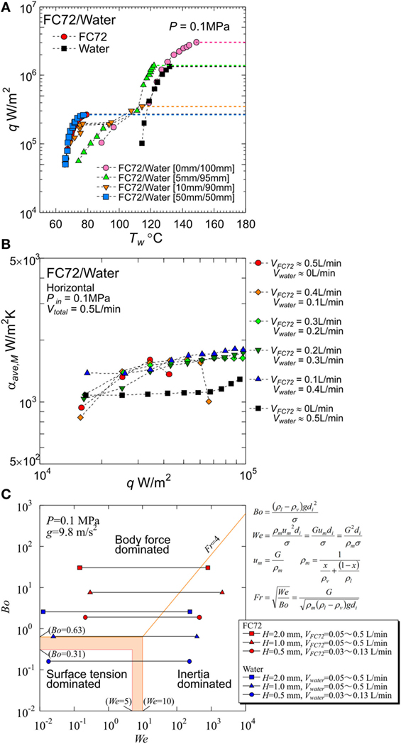
Figure 1. Typical results already obtained by the present authors: (A) significant increase of critical heat flux by using immiscible mixture from 1.4 × 10⁶ W/m2 for pure water to 3.0 × 10⁶ W/m2 by the small addition of FC72 observed in pool boiling experiment (Ohta et al., 2015), (B) enhancement of heat transfer due to forced convection of water by nucleate boiling of FC72 observed in flow boiling experiments using a round tube (Yamasaki et al., 2015), (C) dominating force regime map by Bond, Weber and Froude numbers, obtained from flow boiling experiments using mini-tubes with different orientations (Baba et al., 2012).
The immiscible mixtures as cooling fluids have superior heat transfer characteristics when they are used under nucleate boiling conditions in a pool or an enclosed vessel. However, for practical applications, the system of flow boiling is more general and useful, because it separates the location of final heat dissipation, i.e., condenser section, from the location of heat generation, i.e., cold plate. By a part of present authors, flow boiling of immiscible mixture in a round tube was investigated (Yamasaki et al., 2015; Ohta et al., 2016). The experiments were performed by using a horizontal heated tube with an inner diameter of 7 mm and a heated length of 310 mm. The local heat transfer coefficients along the tube axis were measured by using an immiscible mixture of FC72/water under the conditions of pressure 0.1 MPa, inlet temperature 47°C, and total flow rate of 0.5 L/min. Before heating, flow pattern of liquid–liquid and vapor of the components was clarified. The flow pattern was not largely changed by the generation of FC72 bubbles because the generated bubbles did not penetrate into the liquid of water. For a small ratio of FC72 flow rate to the total, emulsion-like flow was observed under the unheated condition, where almost uniform distribution of fine FC72 droplet in the cross section of tube was exceptionally realized. Measurements of heat transfer coefficients were performed under different flow rate combinations. For all ratios of FC72 flow rate to the total varied as 0.2–0.8, values of CHF were increased from pure FC72, and heat transfer coefficients were enhanced from those of water in the entire heat flux range tested. The increment of the heat transfer coefficients became maximum at the FC72 flow rate ratio of 0.2, where emulsion-like flow was observed under the unheated condition. The results were attributed to the distribution of FC72 liquid along entire circumferential area of tube wall.
Because the distribution of both component liquids with different densities is not uniformly distributed across the cross section of a horizontal tube due to the existence of gravity, the heating of both components is not uniform in the circumferential direction of a tube even under the uniform heating from the tube wall. Furthermore, an additional thermal resistance is unavoidable when the dissipated heat is transferred to the tube wall from the flat surfaces with heat generation, such as surfaces of semiconductors or of heat spreaders. Therefore, the use of a rectangular channel is desired and tested here. From the experimental results of pool boiling, the role of more-volatile liquid is very important for the initiation of boiling at low surface temperature, and for the enhancement of heat transfer compared with pure less-volatile component, as explained in (ii) and (iii), respectively, in the preceding paragraph. If the gap size is small for the rectangular channel horizontally oriented, both component liquids contact the heating surface located at the bottom of channel even if the density of more-volatile liquid is lower than the less-volatile liquid. The use of narrow channels has another application. Because the representative length of the channel is reduced approximately to two times of the gap size for a large channel width compared to the gap size, the behaviors of liquid–vapor interface are dominated by surface tension rather than the body force. As a consequence, the phenomena become independent of gravity, which is an advantageous feature for the use of cooling system in space after the verification of the performance on the ground, or in automobiles accompanied by the frequent change of gravity vector during the operation.
There are many researches concerning boiling in narrow spaces. Fujita et al. (1989) conducted the experiment in narrow gaps between flat plates for various orientations including the vertical one immersed in a pool of water. They clarified the heat transfer enhancement by the reduction of gap size between plates, but it turned to the heat transfer deterioration by further decrease of the gap size due to the extension of large dry patches underneath large flattened bubbles. Willingham and Mudawar (1992) clarified the relation between CHF and gap sizes in narrow channels. Under the constant inlet velocity of liquid FC72, CHF values take a maximum at the intermediate gap size between 2 and 10 mm. They explained the reason of the trend by the coexistence of the positive effect due to the increase of liquid–vapor mixture velocity and the negative effect by the extension of dry patches with decreasing gap size. Lee and Lee (2001) investigated flow boiling heat transfer in narrow rectangular channels. They clarified the effect of gap size under various combinations of mass velocity, vapor quality, and heat flux. Their data showed that, in the region of two-phase forced convection, the heat transfer was enhanced and the effect of mass velocity is decreased with the reduction of gap size.
Kandlikar (2006) summarized the results of flow boiling in microchannels and minichannels with reference to the existing papers. According to his explanation, an expanding-bubble which occupied the entire cross section of channel formed the liquid film between the bubble and the heated wall, and the behavior of liquid film was similar to nucleate boiling and was quite different from the annular liquid film flow observed in normal channels. The heat transfer mechanism during flow boiling in microchannels and minichannels was regarded as being similar to nucleate boiling. He indicated that the behavior of three-phase interline was directly related to CHF mechanism, and the importance of “vapor-cutback” phenomenon to separate liquid film from the heated wall by the momentum of vapor due to the evaporation was proposed. Kandlikar et al. (2013) summarized five different instabilities or origin of instabilities possible for flow boiling in microchannels, where the rapid bubble growth toward upstream, the upstream compressible volume due to the existence of incondensable gas, and the CHF condition to restrict liquid flow were related to the experiments performed here by the present authors. A part of present authors already checked the effect of bubble growth toward upstream in a mini-tube of 0.51 mm in diameter by using FC72, in which the results with and without upstream compressible volume were compared (Ohta et al., 2009). The compressible volume was realized by the installation of a buffer tank with a built-in bellow whose back was exposed to the atmosphere. With the compressible volume, heat transfer deterioration in the region of two-phase forced convection occurs due to the periodical flow fluctuation, while the heat transfer characteristics was qualitatively similar to those of normal tubes without compressible volume.
The application to the cooling of semiconductor chips is targeted in most recent researches for flow boiling in microchannels, where the width of rectangular channels is comparable with its depth, and the one-dimensional behaviors of bubbles are concerned, once they occupy the entire cross section of the channel. However, in the narrow channel discussed here, the ratio of width to depth is quite large, and bubbles continue to grow in the transverse direction perpendicular to the flow even after they contact the surface located opposite to the heating surface.
Before the experiments, the gap sizes adopted here are examined on the regime map of dominant forces of body force, surface tension and inertia as shown in Figure 1C, where Bond, Weber, and Froude numbers are selected as parameters. The inertia force varies with mass velocity and vapor quality and is evaluated by the mean density of liquid–vapor mixture under the assumption of no slip between the phases. The boundaries of dominant regimes were decided from the results of flow boiling experiments by a part of the present authors, in which Bond number was reduced by the employment of mini-tubes and its orientation was varied to examine the influence of gravity on the heat transfer (Baba et al., 2012). The keys represent the range of experimental conditions of pure components, FC72 and water described later.
To clarify the heat transfer performance in boiling of immiscible liquids for the application to the practical cooling systems, the experiments on flow boiling in narrow rectangular channels with different gap sizes are conducted.
Experimental Apparatus and Procedure
The test loop, shown in Figure 2A is composed of one pump circulating both component liquids, flow meters, preheater, test section, condenser, and separation tank. The pressures inside the test loop is adjusted by the flow rate of water as a coolant in the condenser with reference to the heat inputs from the preheater and the test section. The magnet gear pump (IWAKI, MDG-M4T6A100) has a maximum discharge rate of 4.6 L/min. Its revolution is controlled by the inverter with reference to the pulse signal from the main flow meter located at the downstream of the pump. The test loop has three flow meters, i.e., one (OVAL, LFS45) at the downstream and two (OVAL, LFS40) at the upstream of the pump. All of flow meters have oval gears whose pulse signal is converted to the voltage to control the pump revolution. The error of flow rate in this system is ±1.6% evaluated from the specification of the flow meters. The preheater is made in the laboratory of the authors, where the sheathe heaters (SAKAGUCHI E.H., ELECTRIC, A-16, O.D. 8 mm) are wound around a copper tube. The preheater is wrapped by sheets of glass wool to reduce the heat loss as much as possible for the accurate evaluation of the inlet condition of the heated test section by the heat balance. The condenser is composed of a commercial-grade heat exchanger (HISAKA WORKS, BXN-024-NU-30), where cold water is supplied from a chiller unit (ORION, RKE1500B-V-G2-P, cooling capacity: 5.3 kW at water temperature of 20°C, minimum flow rate: 21 L/min) at desired temperature and flow rate. The separation tank is an important component for the experiment using the immiscible liquids. The vertical Pyrex glass cylinder has two aluminum flanges at the top and bottom of it. To prevent the leak of liquid, O-rings are inserted in them. From the bottom flange, a tube connected to the downstream is extended upwards to the thick layer of liquid with smaller density to suck it, while the liquid of larger density is introduced to the downstream separately from a hole located at the bottom flange. By the structure, each component liquid is introduced independently to the circulating pump. The flow rates of both liquids are controlled by using manual valves with reference to the flow meters. The pressure of the test loop is monitored by Bourdon pressure gauge (NAGANO KEIKI, AC10-173-3000, 0–1.1 MPa) for the safety of the experiment. The inlet pressure of the test section and pressure drop across it are measured by the pressure transducers (VALIDYNE, P55D 1-E-2-48-W-4-A, 0–350 kPa and P55D 1-E-2-46-W-4-A, 0–550 kPa, respectively), where the error of ±1.4 and ±0.9% are expected. The temperatures inside the loop are measured by K-type thermocouples (SANKO, T-35, sheath diameter: 1.6 mm) and their cold junctions are kept at 0°C by the controller of reference temperature (COPER ELECTRONICS, Zero-con ZC-114). The error of temperature measurement is ±0.3 K taking account also of the accuracy of data acquisition system described later.
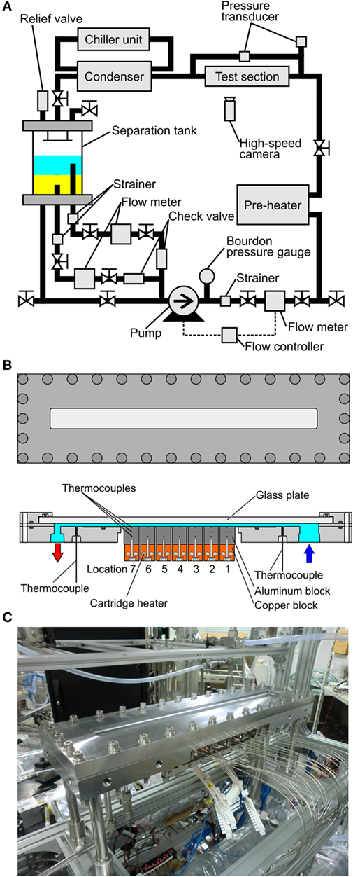
Figure 2. Test loop and test section: (A) test loop with one pump circulating both component liquids of immiscible mixture, (B) test section with a heating surface for the measurement of local heat transfer characteristics, (C) outlook of heated test section with a horizontal heated channel.
The structure of the test section and its photo are shown in Figures 2B,C, respectively. The test section is composed of a narrow channel between two flat plates, where one is a heating surface and the other is a glass plate for the observation. The channel has a rectangular cross section of 30 mm in width and its gap size is varied as 2, 1, and 0.5 mm. The test section is assembled by using stainless flanges and O-rings. The heating surface assembly, which has a heated area with a width of 30 mm and a length in the flow direction of 175 mm located at the bottom of the horizontal channel, consists of seven segmental aluminum blocks with a length of 25 mm cut out in one unit body to prevent the preferential nucleation at the boundaries of the blocks. If the neighboring segment surfaces are soldered, the bubble nucleation occurs preferentially at the boundaries of segments because many defects such as fine holes and crevices are activated as nucleation sites. Each block has thermocouples at different depths of 1.5, 8.5, and 15.5 mm to evaluate local heat transfer coefficients. Local surface temperatures and local heat fluxes are evaluated by using measured temperature gradients. Because the heat flux is not evaluated from the power input to the cartridge heaters, the accuracy of evaluated local heat fluxes is influenced also by the accuracy of thermocouple locations.
The evaluated error of heat flux is ±2.9% independent of heat flux level. The error of surface temperature, obtained by the extrapolation of temperature gradient to the surface, is estimated as ±0.07 and ±0.75 K at 5 × 10⁴ and 5 × 10⁵ W/m2, respectively. The error of the surface temperature, evaluated as the summation of the errors due to measurement, i.e., ±0.3 K and due to the uncertainty of thermocouple location above mentioned, becomes ±0.37 and ±1.05 K at 5 × 10⁴ and 5 × 10⁵ W/m2, respectively. The largest heat transfer coefficients for these heat fluxes are 6.6 × 10³ and 2.6 × 10⁴ W/m2 K from the experimental results shown later (cf. Figure 12) and the corresponding smallest temperature differences are 6.25 and 16.6 K, respectively. As a consequence, the maximum error of heat transfer coefficients, evaluated from the errors of the heat flux, i.e., ±2.9% and the errors of temperature difference ±5.0 and ±5.4%, are ±8.3 and ±8.9% for the representative heat fluxes, 5 × 10⁴ and 5 × 10⁵ W/m2, respectively, provided that the local fluid temperatures used for the definition of the local heat transfer coefficients is exactly estimated by the heat balance equation. There is unavoidable ambiguity in the evaluation of fluid temperatures inherent in immiscible mixtures due to the complicated evaporation process accompanied by the non-thermal equilibrium state as described in the beginning of Section “Evaluation of Fluid Temperature Distribution in Flow Direction.”
To prevent the heat conduction toward the flow direction, six slits are located between segmental aluminum blocks which are separated except the thin part at the top, and the individual blocks are almost thermally isolated each other. The cartridge heaters are inserted in the copper blocks attached to each bottom of the aluminum block. To avoid the excessive temperature increase in the copper block and protect the heaters from damage, both blocks are connected tightly by the aid of screws. The structure can change the heated length in the case of dry out at the downstream and the experiment at higher heat fluxes could be possible by switching off the power input to the segments located at the downstream. The test section is installed in the test loop to realize the horizontal channel flow. Before the filling of test liquids, the inside of the test loop is evacuated by a vacuum pump. The evacuation is repeated under the unheated condition before the start of heating to ensure the degassing. The dissolved air especially in a test liquid of FC72 seriously scatters the data acquired. The temperatures and pressures are measurement by a data logger (KEITHLEY, 3706). The images of liquid–vapor behaviors are recorded thorough the glass plate located at the top of the duct by using a high-speed video camera (IDT, MotionXtra N3, Max frame rate: 1,000 fps).
Test liquid is an insoluble mixture of FC72/water. Under the condition of coexistence of both liquids and their vapor, the total pressure is the summation of partial pressures of the components. The situation is represented by vapor pressure curves in Figure 3. One component liquid is subcooled under the compression by vapor pressure of the other component. The liquid of more-volatile component is compressed slightly by low vapor pressure of less-volatile component and small subcooling is imposed. On the other hand, the liquid of less-volatile component is compressed largely by high vapor pressure of more-volatile component and high subcooling is given. The degrees of subcooling for both component liquids are summarized in Table 1. The pressure at the exit of the test section is adjusted at 0.1 MPa. The experimental conditions are listed in Table 2. Bond numbers corresponding to the size of channel gaps and the ranges of Weber numbers are shown in Figure 1C for pure FC72 and water. It is clear that the phenomena will be in the range between gravity-dominated and inertia-dominated except the boiling of water flowing in a channel of 0.5 mm in gap size which is dominated by surface tension or inertia. The representative lengths in the dimensionless groups are evaluated by the equivalent diameters, i.e., doubled gap sizes.
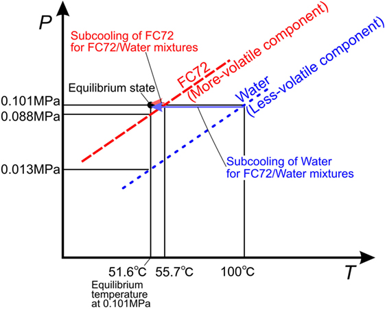
Figure 3. Explanation of states of both component liquids on the vapor pressure curves.
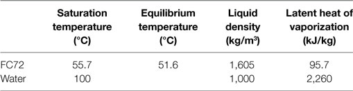
Table 1. Equilibrium temperature and values of liquid subcooling for both component liquids in immiscible mixtures of FC72/water at 0.1 MPa.
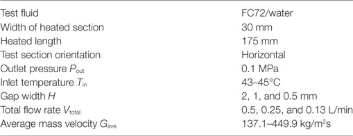
Table 2. Experimental conditions.
Evaluation of Fluid Temperature Distribution in Flow Direction
Although the devised structure of the heating surface assembly mentioned in the preceding section makes possible the evaluation of local surface temperatures, it does not mean the feasible evaluation of local heat transfer coefficients for immiscible mixtures. The estimation of fluid temperature distribution along the flow direction from the measured temperature at the inlet and the outlet of the heated test section is needed to obtain a local value at each segment. There may be individual temperature distributions of FC72 and water along the flow direction, because of the velocity slip between the components which promotes the non-equilibrium state between liquid–liquid and liquid–vapor, and then non-uniform temperature especially between the components at each cross section of local positions. We have no information about the details of the velocity and temperature fields in a channel and the knowledge about interaction between the components are expected in further studies. However, it is at least true that subcooled liquid of FC72 becomes saturated much earlier than water. To apply the conventional energy balance method, three different regions are taken into account depending on the outlet state of mixtures. Along the manner for a round tube (Yamasaki et al., 2015), the uniform temperature across every cross section of the channel is assumed again. Three regions are classified by the different states of more-volatile component, FC72, while the less-volatile component, water, is assumed to be subcooled liquid for all regions.
(Region A) FC72 (Fluid 1): subcooled liquid/water (Fluid 2): subcooled liquid
where ΔQ: heat supplied between neighboring local positions (W), ΔT: temperature increment between neighboring local positions (K), Vl: liquid volumetric flow rate (m3/s), ρl: liquid density (kg/m3), cpl: liquid isobaric specific heat (J/kg K). A parameter ξ represents the rate of heat transferred to FC72 to the total (–). The suffixes 1 and 2 denote the more-volatile component (FC72) and less-volatile component (water), respectively. Once the flow rates of both liquids at the inlet of the test section and the electric power supplied to the heated section are given, the value of ξ is uniquely determined in Region A under the assumption of uniform temperature distribution across the cross section of the heated channel.
(Region B) FC72 (1): superheated liquid and superheated vapor/water (2): subcooled liquid
where, hfg: latent heat of vaporization (J/kg), cpv: isobaric specific heat of vapor (J/kg K). Vapor quality x1 (–) is defined by
If water is also evaporating (not applied here), vapor quality x (–) for both components is defined by
The boundary between the region A and the region B is assumed to be given by the equilibrium temperature, slightly lower than the saturation temperature of FC72, because initiation of nucleate boiling of FC72 is possible at low subcooling as confirmed in Table 1. In Region B, the state of FC72 is regarded as the mixture of superheated liquid and vapor. The temperature of subcooled water increases monotonically along the flow direction even after it exceeds the saturation temperature of FC72. And, also the temperature of FC72 liquid and vapor mixture is assumed to be increased by the same increment with water under the assumption of a uniform temperature in the cross section of the channel. The degree of liquid superheat, estimated from the outlet fluid temperature shown later, is possible values in the range of the quasi-stable state. In Region B, the parameter ξ is evaluated so that the calculated exit temperature coincides with the measured one.
(Region C) FC72 (1): superheated vapor/water (2): subcooled liquid
In this region, liquid of FC72 is completely evaporated. Similar to Region A, ξ is uniquely determined by using properties of vapor and liquid for FC72 and water, respectively.
The calculated exit temperatures are compared with measured values in Figure 4, where the measured exit temperatures are shown by symbols and the calculated temperatures are represented by lines. In the figure, if the exit condition of FC72 is subcooled (Region A), direct comparison between the experimental data and the calculated values by Eqs 1 and 2 are possible. When the exit condition is located in the quality region of FC72 (Region B), which is easily known from the heat balance Eqs 1 and 2 for Region A by the check of exit temperature being larger or smaller than the temperature of boiling initiation, the values of ξ are calculated by using Eqs 3 and 4. After the determination of ξ from scattered values in Figure 5, the calculation is performed again to obtain the calculated exit temperatures for different combinations of flow rates as shown in Figure 4. Further increase in heat flux results in the complete evaporation of FC72, and FC72 is superheated at the exit (Region C). The measured exit temperature increases with increasing heat flux. The calculated exit temperatures are assumed to be the same as the measured ones to eliminate the discrepancy between the values which is resulted from the initiation of water subcooled boiling. The procedure is applied to all conditions in which the increment of exit temperature becomes larger with increasing heat flux at high heat fluxes in Figure 4. For immiscible mixtures, except the data of assumed agreement of exit temperature, the maximum discrepancy between the data and calculated exit temperature is within about ±1 K (to be referred in the latter section as Error #1) under the simplified assumption of uniform temperature across the cross section of the channel. The discrepancy is acceptable for the calculation of the temperature distribution, which is needed for the definition of local heat transfer coefficients.
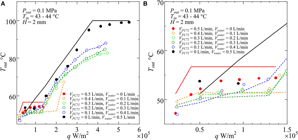
Figure 4. Examples of measured and calculated temperatures at the outlet of test section for various combinations of component liquid flow rates at the inlet of heated test section: (A) entire heat flux range, (B) magnified range in low heat flux.
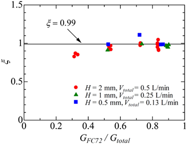
Figure 5. The variation of parameter ξ representing the ratio of heat transferred to more-volatile component FC72 to the total in Region B.
On the other hand, reasons for the discrepancy between the calculated and measured temperatures for pure components are deduced as follows. For both pure components, the calculate value of exit temperature increases monotonously with increasing heat flux under the subcooled liquid condition at the exit, while it becomes saturation temperature at higher heat flux. For FC72, the measured exit temperatures are far smaller than the calculated values. The occurrence of subcooled boiling consumes the supplied heat and reduces the sensible heat transferred to the liquid. The situation is also true for water. The discrepancy becomes smaller by the reduction of subcooling at higher heat flux. In addition, the measured liquid temperature in the bulk flow can become lower by the sensible heat accumulated in the superheated layer when the mixing of liquid is not enough especially at low heat flux. By these reasons, the measured temperatures become smaller than the prediction by the heat balance Eqs 1 and 2. To check the reproducibility of the experimental data for pure water, the experiment was repeated again. However, the trend of the data was the same. In despite of such discrepancy, the calculated temperature distribution along the flow direction is used for both of pure components ignoring the existence of non-equilibrium state.
The value of ξ in Region B is of the most interest in the present analysis. To evaluate the value, the data in which the exit condition is regarded as that of Region B is referred. In Figure 5, the data points at different heat fluxes are plotted by using the same key for one combination of flow rates. The values of ξ is dependent on the combination of flow rates to some extent, while they are almost independent of heat flux. The values of ξ near unity are clear from Figure 6. The distribution of liquid FC72 relative to the location of the surface for heat transfer is quite different between a round tube (Yamasaki et al., 2015) and a rectangular channel. Because of higher density of liquid FC72 than water, most part of heat is transferred directly to FC72 from the heating surface located at the bottom of channel at least for a large gap size. Because the values of ξ are determined from the small temperature increment along the flow direction as shown in Eqs 3 and 4, the sensitivity of ξ against the measured outlet temperature is high. Under the existence of uncertainty caused by the assumption of uniform temperature in the channel cross section, a value ξ = 0.99 is applied here independent of flow rate combination and heat flux for the evaluation of local fluid temperatures at different measurement points on the segmented heating surfaces. In the case of higher ratio of FC72 flow rate to the total, the calculated values of ξ from the measured exit temperature exceed unity. The contradictory trend is caused by the measured exit temperature is lower than the exact value because of the flow fluctuation often observed under such flow rate conditions. For the data at H = 0.5 mm and Vtotal = 0.13 L/min, the most extreme case in Figure 5, the difference between the values of ξ = 1.11 and ξ = 0.99 corresponds to the error of the measured temperature by −2.3 K (Error #2).
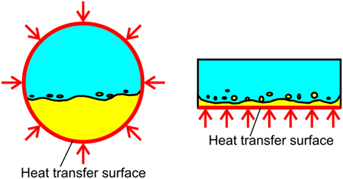
Figure 6. Difference in the distribution of more-volatile liquid with higher density on the heating surface between a round tube and a rectangular channel with heating of a bottom surface.
An example of fluid temperature distribution along the flow direction is shown in Figure 7A, which is used for the evaluation of local heat transfer coefficients at each segment. The value of ξ = 0.99 is applied to all combinations of flow rates. After FC72 is completely evaporated (Region C) and subcooled boiling of water is expected apart from the assumption in Eqs 7 and 8, linearly interpolated values of measured fluid temperature at the exit of test section and calculated temperature at the end of Region B are used to determine the fluid temperature distribution. It is clear that the increment of temperature in the quality region of mixed FC72 (Region B) is very small because only 1% of heat is transferred to water as sensible heat. As the ratio of FC72 flow rate to the total is increased, the length of Regime B along flow direction increases as is expected. The difference in the levels of temperatures for the quality region of mixed FC72 between different combinations of flow rates is caused by the small difference in the system pressure during the experiments. To examine the effect of heat flux, a trial to increase heat flux from q = 2 × 10⁵ to q = 4 × 10⁵W/m2 is performed keeping other conditions for Figure 7A unchanged. The result is shown in Figure 7B, where the exit temperatures for VFC72 = 0.5 L/min, Vwater = 0 L/min and VFC72 = 0.4 L/min, Vwater = 0.1 L/min at q = 2 × 10⁵ W/m2 were applied again because of no measured exit temperatures at q = 4 × 10⁵ W/m2, which is larger than CHF values for these fluids. It is clear that the length of Region B, in which the evaporation of mixed FC72 occurs, is reduced by the increase of heat flux.
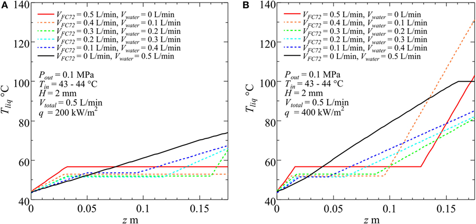
Figure 7. Examples of evaluated temperature distribution along the flow direction for various combinations of component liquid flow rates at the inlet of heated test section. (A) q = 200 W/m2, (B) q = 400 W/m2.
The error of pressure measurement at the inlet of the heated test section is already evaluated as ±1.4% in Section “Experimental Apparatus and Procedure,” which corresponds to ±0.0014 MPa for the system pressure of 0.1 MPa. Because the sensitivity of equilibrium temperature to the pressure is 1.98 × 10² K/MPa independent of concentration for immiscible mixtures, the error of measured pressure corresponds to the error of calculated temperature of ±0.28 K (Error #3). By the way, for pure liquids of FC72 and water, the sensitivity of saturation temperature to the pressure is 2.93 × 10² and 2.80 × 10² K/MPa, which results in the errors of ±0.41 and ±0.39 K, respectively.
Experimental Results and Discussion
Typical results for gap size of H = 1 mm is represented in Figures 8–11, where (a) the surface temperature Tw versus heat flux q, (b) heat transfer coefficient α versus heat flux q, (c) liquid–vapor behaviors at selected heat fluxes are shown. For the purpose of the practical application, the use of surface temperature instead of the temperature difference between the heating surface and fluid is attempted along the method of data reduction for pool boiling, cf. Figure 1. In pool boiling, because the equilibrium temperature is lower than either of saturation temperatures of the components under a given system pressure, the performance of heat transfer due to nucleate boiling is underestimated if it is evaluated by using the temperature difference between the heating surface and subcooled liquid. In flow boiling, however, heat transfer coefficients are defined by using the fluid temperature regardless of its state. Depending on the combination of flow rates and heat flux, the deviation of inlet pressure from the adjusted outlet value of 0.1 MPa is unavoidable. Such influence is reflected to the experimental data implicitly. In a series of data in Figures 8–11, the total volumetric flow rate is fixed at Vtotal = 0.5 L/min.
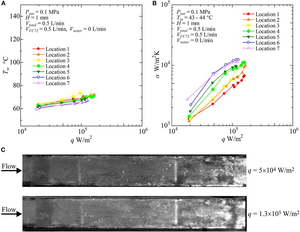
Figure 8. Distribution of local heat transfer coefficients along the flow direction versus heat flux, and corresponding flow behaviors (H = 1 mm, Vtotal = 0.5 L/min, pure FC72), (A) Tw − q, (B) α − q, (C) liquid–vapor behaviors at selected heat fluxes.
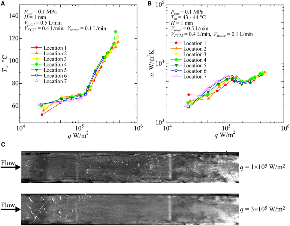
Figure 9. Distribution of local heat transfer coefficients along the flow direction versus heat flux, and corresponding flow behaviors (H = 1 mm, Vtotal = 0.5 L/min, VFC72 = 0.4 L/min, Vwater = 0.1 L/min): (A) Tw − q, (B) α − q, (C) liquid–vapor behaviors at selected heat fluxes.
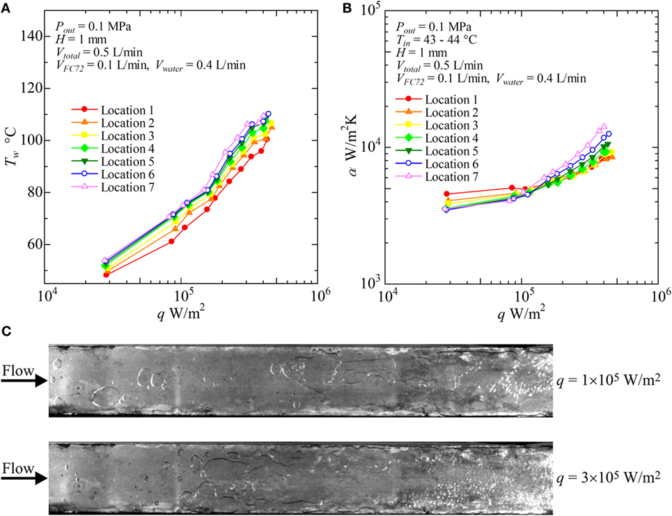
Figure 10. Distribution of local heat transfer coefficients along the flow direction versus heat flux, and corresponding flow behaviors (H = 1 mm, Vtotal = 0.5 L/min, VFC72 = 0.1 L/min, Vwater = 0.4 L/min): (A) Tw − q, (B) α − q, (C) liquid–vapor behaviors at selected heat fluxes.
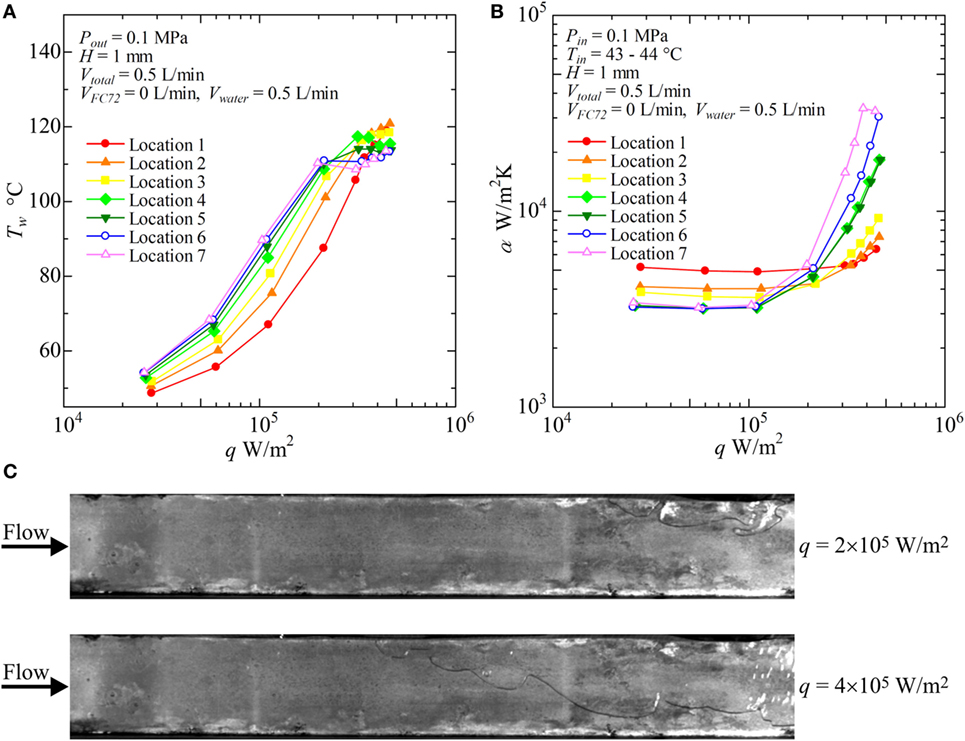
Figure 11. Distribution of local heat transfer coefficients along the flow direction versus heat flux, and corresponding flow behaviors (H = 1 mm, Vtotal = 0.5 L/min, pure water): (A) Tw − q, (B) α − q, (C) liquid–vapor behaviors at selected heat fluxes.
Figure 8 shows the result for pure FC72 (VFC72 = 0.5 L/min, Vwater = 0 L/min). The surface temperatures do not change largely with increasing heat flux because nucleate boiling dominates the heat transfer. This is confirmed again by the trend of heat transfer coefficients dependent strongly on the heat flux as is observed in pool boiling experiments (Figure 8B). The increasing level of the heat transfer coefficients defined by the fluid temperature is resulted from the decrease in liquid subcooling toward the flow direction. The condition of CHF is observed at around 1.3 × 10⁵W/m2 in the downstream locations. As shown in Figure 8C, the distinct bubble generation due to nucleate boiling is started from the both side edges of the channel at the upstream because the flow velocity of liquid is small near the side edges resulting in thicker thermal boundary layer required for the initiation of nucleate boiling. By using movie images, the bubble nucleation is also confirmed along the center of the heating surface even in the upstream region. However, because of the subcooling of FC72 liquid at the upstream of the test section, small bubbles do not grow. The saturated condition is extended from both side edges toward the center. These behaviors are usual for flow boiling in narrow channels.
In Figure 9, the results for VFC72 = 0.4 L/min, Vwater = 0.1 L/min are shown. The surface temperatures start to increase significantly at heat flux of around 1.3 × 10⁵ W/m2 in all locations of measurement on the heating surface. The heat transfer is dominated mainly by subcooled nucleate boiling of FC72 at the heat fluxes below 1.3 × 10⁵ W/m2. At the relevant boundary heat flux, a symptom of heat transfer deterioration due to the extension of dry patches under the flattened bubbles of FC72 is deduced by the change in the gradients of characteristic curves in both of Figures 9A,B. The phenomena is already known as “intermediate heat flux burnout” by the present authors during the pool boiling experiments, where the accumulation of bubbles composed of more-volatile component becomes a trigger of small surface temperature excursion (Kobayashi et al., 2012; Ohnishi et al., 2013; Kita et al., 2014; Ohta et al., 2015). Even in such a case, the serious heat transfer deterioration accompanied by the catastrophic surface temperature excursion can be avoided by the lateral penetration of less-volatile liquid as an alternative cooling medium in place of more-volatile liquid. The coexistence of the dried area underneath FC72 bubbles and the rewetted area by water flow makes possible the stable heat transfer at higher heat fluxes, but the behavior results in the larger increment of surface temperature with increasing heat flux. As a result, heat transfer coefficient temporarily tends to decrease as shown in Figure 9B. However, by the addition of water at small flow rate to the flow of FC72, CHF conditions at 1.3 × 10⁵ W/m2 observed for pure FC72 in Figure 8 can be avoided. As shown in Figure 9B, the heat transfer deterioration is increased because the area of dry patches is extended with increasing heat flux up to 2 × 10⁵ W/m2. The heat transfer coefficient, dominated mainly by forced convection of water, starts to increase again by further increase of heat flux, because the flow velocity of water is increased by the volume of generated FC72 bubbles. In Figure 9C, both of liquid flow of water and the generation of FC72 flattened bubbles are observed at 1 × 10⁵ W/m2, and the heat transfer is dominated by nucleate boiling of FC72 as is confirmed also from the trend of heat transfer data in Figures 9A,B. At heat fluxes 3 × 10⁵ W/m2, the distinct flow of water is observed at the edge of the rectangular duct and along the opposite unheated plate because of the phenomena corresponding to the annular flow in a tube at high vapor flow rate of evaporated FC72. Under such a case, only a part of water seems to flow along the heating surface. During the experiment, the liquid–vapor behavior is never steady but periodical at high heat fluxes because of the bubble expansion also toward the upstream direction in the narrow channel as is observed in usual in mini- and micro-channels. If the flow rate of water is further increased by decreasing the flow rate of FC72 under the same total volumetric flow rate, the temporal heat transfer deterioration due to the increased area of dry patches underneath the flattened bubbles of FC72 might be suppressed at the boundary heat flux at which the dominated heat transfer is changed from the nucleate boiling of FC72 to the forced convection of water.
With increasing water flow rate as VFC72 = 0.4, 0.3, 0.2, 0.1 L/min and Vwater = 0.1, 0.2, 0.3, 0.4 L/min, respectively, the increase of surface temperature is suppressed and the heat transfer coefficients take higher values. In Figure 10, the results for VFC72 = 0.1 L/min and Vwater = 0.4 L/min are shown. It is noteworthy that the heat transfer coefficients at the downstream location are clearly higher than those for the upstream under high heat flux conditions. This is because only the positive effect of FC72 bubbles on the heat transfer becomes emphasized by the reduction of FC72 flow rate. The increased agitation and the squeeze of water film by FC72 flattened bubbles enhance the transient heat conduction from the heating surface to the film, and the positive effect overcomes the negative effect of dry patch extension underneath FC72 flattened bubbles at high heat flux. From Figure 10C, large flattened bubbles of FC72 are observed at all locations of the heating surface. At the downstream, nucleate boiling of water occurs at 3 × 10⁵ W/m2 which also enhances the heat transfer because the flattened bubbles of FC72 are not excessively large under the smaller flow rate of FC72.
For pure water (VFC72 = 0 L/min, Vwater = 5 L/min), as shown in Figures 11A,B, the surface temperatures increase with increasing heat flux before the initiation of boiling at high heat flux. The heat transfer is dominated by forced convection. The heat fluxes for the initiation of boiling are around 2 × 10⁵ W/m2 in the midstream and the downstream locations. The heat flux needed for the boiling initiation at the upstream are higher because of large subcooling. At low heat flux, the heat transfer is dominated by forced convection, and the heat transfer coefficient takes higher value at the upstream as shown in Figure 11B because of thinner thermal boundary layer near the entrance. The heat transfer coefficients in nucleate boiling are higher in the downstream because of the positive effect by flattened bubbles. However, the symptom of CHF condition is observed in the heat transfer coefficient for Location 7 at the highest heat flux. In Figure 11C, nucleate boiling of water is clearly confirmed in the downstream location at 4 × 10⁵ W/m2, while the heat transfer is dominated by forced convection at the upstream.
The effect of channel gap size is summarized in Figures 12–14 for H = 2, 1, and 0.5 mm, respectively. In these figures, the data for Location 6, cf. Figure 2B, are represented because the characteristics of flow boiling in narrow channels are emphasized in the downstream region. Inlet velocity is unified among the data shown here, and the total flow rates are Vtotal = 0.5, and 0.25, and 0.13 L/min for H = 2, 1, and 0.5 mm, respectively. The errors of heat transfer coefficient, estimated by the manner described in Section “Experimental Apparatus and Procedure” are shown in the figures by using error bars of solid vertical lines and maximum error values at selected heat fluxes are also given in the caption of figure. The accuracy of data depends on the errors of heat flux, surface temperatures and fluid temperature. The former two are reflected in this error estimation, while the error of fluid temperature could not be reflected because of the unknown discrepancy between the real temperature distribution in the flow direction and the calculated one under the assumption of uniform temperature across each cross section of channel. However, as known from the discussion in Section “Evaluation of Fluid Temperature Distribution in Flow Direction,” the error of fluid temperature at the exit of the heated test section is around ±1 K (Error #1), and the error of temperature during the evaporation of FC72 caused by the error of pressure-dependent equilibrium temperature is estimated as ±0.28 K (Error #3), respectively, for mixtures. Furthermore, the error of fluid temperature caused by the error of ξ in the most extreme case is around −2.3 K (Error #2). To reflect these errors in the evaluation of fluid temperature, the error bars are extended as a trial in two steps taking account of additional errors of ±1 and ±3 K, respectively, by vertical dotted lines. The evaluation of accurate fluid temperature distribution is required in further studies on flow boiling of immiscible mixtures by using an experimental setup optimized for the direct measurement of fluid temperature distributions in both the flow direction and the channel cross section.
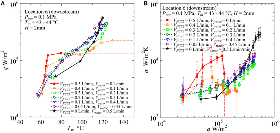
Figure 12. Effect of gap size on the heat transfer coefficient in the downstream under the constant liquid flow velocity at the inlet of heated test section (H = 2 mm, Vtotal = 0.5L/min): (A) q − Tw, (B) α − q. (Maximum errors caused by the uncertainty of heat flux and surface temperature measurement: heat flux ±2.9% independent of heat flux level, surface temperature ±5.0 and ±5.4%, heat transfer coefficient assuming accurate fluid temperature ±8.3 and ±8.9% at heat fluxes 5 × 10⁴ and 5 × 10⁵ W/m2, respectively. The error of heat transfer coefficient is further increased by taking account of the error in the estimation of fluid temperature, and the error bars by solid lines reflecting only uncertainties in heat flux and surface temperature are extended by dotted lines in two steps for the assumed additional errors of fluid temperature as ±1 and ±3 K, respectively, along the discussion in Sections “Evaluation of Fluid Temperature Distribution in Flow Direction” and “Experimental Results and Discussion.”).
In Figure 12, for H = 2 mm, the value of CHF for pure FC72 is around 1.4 × 10⁵ W/m2. The CHF value can be increased by only the addition of water flow and it is increased up to 2.2 × 10⁵ W/m2 for VFC72 = 0.4 L/min, Vwater = 0.1 L/min. The values for other flow rate conditions could not be measured because of flow fluctuation at high heat flux near CHF conditions. However, at least the value larger than 4.5 × 10⁵ W/m2 is confirmed for the water flow rates larger than Vwater = 0.2 L/min or 40% of the total. Even at the small flow rate of FC72, e.g., VFC72 = 0.05 L/min, Vwater = 0.45 L/min, generated bubbles of FC72 coalesce at the midstream and produces vapor core flow squeezing liquid water by the interfacial shear stress to flow along the inner channel surfaces. The distribution of both phases is similar to annular flow in a tube. A large oscillation pushes periodically the flow toward the upstream and there is an instance when the flow is completely stopped. At high heat flux, the large extension of dry patches is observed in the midstream and downstream regions leaving many liquid droplets on the heating surface. The evaporation of the droplets prevents the transition to the CHF condition before the quenching of dry patches by the restarting of liquid flow. Smaller volumetric flow rate of FC72 mixed in water is expected to increase CHF for pure water also in flow boiling because of self-sustained subcooling inherent in boiling of immiscible mixtures. At moderate heat flux, the surface temperatures for immiscible mixtures are clearly lower than pure water but larger than FC72, which indicates that the heat transfer is dominated by the simultaneous nucleate boiling of FC72 and the forced convection of water. On the other hand, the surface temperature increases larger than water at high heat flux, and the trend is emphasized as the flow rate of FC72 is larger. In the upstream, the surface temperatures for these immiscible mixtures, larger than pure water at high heat flux, are not observed because the size of FC72 bubbles is still smaller and the instantaneous extension of dry patches by the existing flow oscillation is small. For VFC72 = 0.4 L/min, Vwater = 0.1 L/min, the heat transfer deterioration due to the intermediate heat flux burnout, cf., Figure 1A, is observed at around 1.3 × 10⁵ W/m2. However, it tends to disappear with increasing flow rate of water. The reduction of surface temperature compared to water observed in immiscible mixtures at moderate heat fluxes is caused also by the increased velocity and the agitation of water flow due to the generation of FC72 flattened bubbles in addition to the evaporation of FC72. In Figure 12B, at heat flux larger than 2 × 10⁵ W/m2 for immiscible mixtures of VFC72 = 0.2 L/min, Vwater = 0.3 L/min and VFC72 = 0.1 L/min, Vwater = 0.4 L/min, the heat transfer deterioration compared to pure water is observed in despite of smaller surface temperatures at heat fluxes less than 3 × 10⁵ W/m2 as shown in Figure 12A. This contradictory trend is caused by the lower fluid temperature near the equilibrium one of immiscible mixtures due to the evaporation of FC72 as shown in Figure 7. As known from Figures 12A,B, no discontinuity in the trend of data for immiscible mixtures along the change of compositions is observed in the range of heat flux larger than 1.5 × 10⁵ W/m2.
In Figure 13 for H = 1 mm, shortage in the data points of pure FC72 is due to the dry out at very low heat flux. The CHF values for FC72 are around 1.3 × 10⁵, 1.2 × 10⁵, and 6.6 × 10⁴ W/m2 in the upstream (Location 2), midstream (Location 4), and downstream (Location 6), respectively, where the value for the downstream is confirmed in the figure. The devised segmented structure of heating block shown in Figure 2B makes possible the change of heated length during the experiment in the case of dry out which propagates from the downstream as the increase of heat flux. At high heat flux, the heat transfer deterioration, regarded as a symptom of dry out, is obvious for pure water as confirmed in Figure 13B. By the small addition of water to the flow of FC72 at VFC72 = 0.2 L/min, Vwater = 0.05 L/min and VFC72 = 0.15 L/min, Vwater = 0.1 L/min, the marked increase in CHF from the value for pure FC72 is observed, however, the surface temperature also increases seriously with the increase of heat flux. The large increase in the surface temperature is caused by the reduction of gap size up to 1 mm. At the midstream, the quick growth of FC72 flattened bubbles promotes the extension of dry patches on the heating surface and, at the same time, pushes water around FC72 bubbles to rewet the dried areas. The penetration of water deactivates the nucleation sites for boiling of FC72 at moderate heat flux, and also has a trend to suppress boiling of water even at high heat flux. On the other hand, the penetration of FC72 results in the instantaneous growth of FC72 bubbles which pushes surrounding liquid and bubbles of FC72 and liquid water. Due to the small gap size of 1 mm, the quenching of dry patches also by water occurs frequently in addition to the quenching by liquid FC72 by the increased secondary flow, and the quenching frequency is increased. As a consequence, the flow oscillation becomes smaller than the case of 2 mm gap size. At the downstream, the flow of liquid and vapor becomes rivulets oscillating in the transverse direction and it seems to accelerate quenching of dry patches. When the flow rate of water is increased, i.e., VFC72 = 0.1 L/min, Vwater = 0.15 L/min and VFC72 = 0.05 L/min, Vwater = 0.2 L/min, the surface temperatures are kept at lower than pure water in the moderate heat flux because the extension of dry patches due to the generation of FC72 bubbles is decreased. However, the heat transfer coefficients are superficially deteriorated from pure water at moderate heat flux because of the lower fluid temperature as is the gap size of 2 mm. When the heat transfer coefficients of H = 1 mm for VFC72 = 0.1 L/min, Vwater = 0.15 L/min and VFC72 = 0.05 L/min, Vwater = 0.2 L/min are compared with those for H = 2 mm at the same flow rate ratios and the same inlet liquid velocity, i.e., VFC72 = 0.2 L/min, Vwater = 0.3 L/min and VFC72 = 0.1 L/min, Vwater = 0.4 L/min in Figure 12, the surface temperatures are lower and the heat transfer coefficients are higher for H = 1 mm than for H = 2 mm at high heat flux. The reduction of gap size results in no serious heat transfer deterioration provided that the flow rate ratio of more-volatile liquid to the total is kept small to suppress the excessive generation of its flattened bubbles. The decreased flow oscillation by the increased frequency to quench dry patches and the enhanced penetration of liquid water prevents large extension of dry patches underneath FC72 bubbles. As a result, the positive effect of flattened bubbles to promote the heat transfer becomes more clear in this gap size.
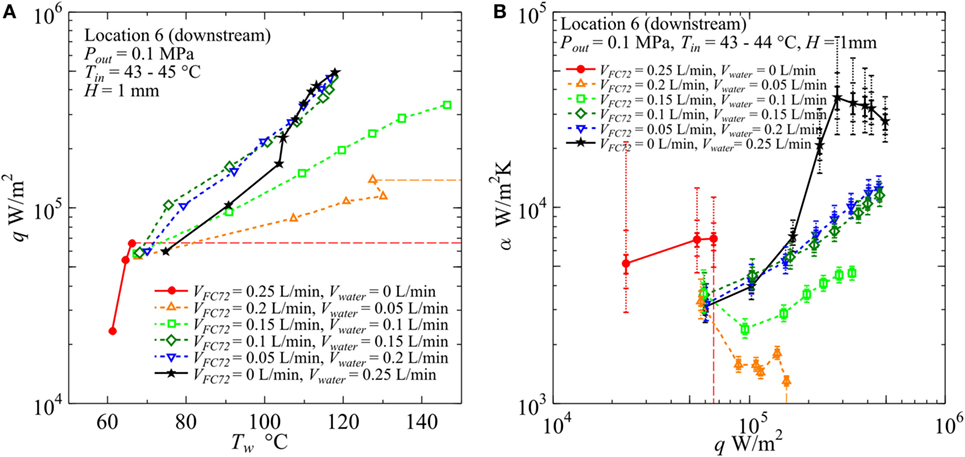
Figure 13. Effect of gap size on the heat transfer coefficient in the downstream under the constant liquid flow velocity at the inlet of heated test section (H = 1 mm, Vtotal = 0.25 L/min): (A) q − Tw, (B) α − q. (Maximum errors caused by the uncertainty of heat flux and surface temperature measurement: heat flux ±2.9% independent of heat flux level, surface temperature ±5.0 and ±5.6%, heat transfer coefficient assuming accurate fluid temperature ±8.3 and ±9.1% at heat fluxes 5 × 10⁴ and 5 × 10⁵ W/m2, respectively. The error of heat transfer coefficient is further increased by taking account of the error in the estimation of fluid temperature, and the error bars by solid lines reflecting only uncertainties in heat flux and surface temperature are extended by dotted lines in two steps for the assumed additional errors of fluid temperature as ±1 and ±3 K, respectively, along the discussion in Sections “Evaluation of Fluid Temperature Distribution in Flow Direction” and “Experimental Results and Discussion.”).
The heat transfer characteristics are quite different for gap size H = 0.5 mm as shown in Figure 14. The CHF values for pure FC72 are around 1.1 × 10⁵, 8.0 × 10⁴, and 6.2 × 10⁴ W/m2 in the upstream (Location 2), midstream (Location 4), and downstream (Location 6), respectively, in which the value for the downstream is confirmed in the figure. Compared to H = 1 mm, the reduction of CHF in the midstream is clear, while the CHF values are not seriously decreased in the downstream. This is because, in the downstream, the dry patches are quickly quenched by penetrating liquid as a result of the rapid exchange of bubble and liquid on the heating surface. For pure water, the deterioration of heat transfer coefficient is observed at high heat flux. For all immiscible mixtures tested here, the surface temperature becomes higher and the heat transfer coefficients take lower values than water with the increase of flow rate ratio of FC72 to the total. The deteriorated heat transfer is clear in Figure 14B at high heat fluxes for all immiscible mixtures compared to pure water, where dry patches are extended quickly under the flattened bubbles of FC72 and they are rewetted at high frequency by the penetration of liquid mostly occupied by water from various directions. As a consequence, a large temperature fluctuation due to the repeated quenching process is observed without causing temperature excursion of CHF condition. The extremely small flow rate of FC72 beyond the present experimental range still has a possibility to enhance the heat transfer for pure water if heat flux is not high.
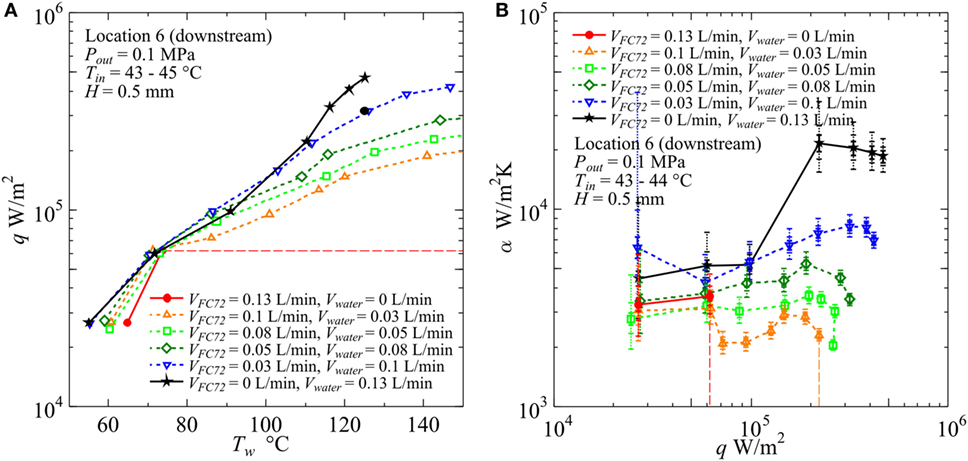
Figure 14. Effect of gap size on the heat transfer coefficient in the downstream under the constant liquid flow velocity at the inlet of heated test section (H = 0.5 mm, Vtotal = 0.13 L/min): (A) q − Tw, (B) α − q. (Maximum errors caused by the uncertainty of heat flux and surface temperature measurement: heat flux ±2.9% independent of heat flux level, surface temperature ±3.7 and ±3.8%, heat transfer coefficient assuming accurate fluid temperature ±6.9 and ±7.0% at heat fluxes 5 × 10⁴ and 5 × 10⁵ W/m2, respectively. The error of heat transfer coefficient is further increased by taking account of the error in the estimation of fluid temperature, and the error bars by solid lines reflecting only uncertainties in heat flux and surface temperature are extended by dotted lines in two steps for the assumed additional errors of fluid temperature as ±1 and ±3 K, respectively, along the discussion in Sections “Evaluation of Fluid Temperature Distribution in Flow Direction” and “Experimental Results and Discussion.”).
For the higher performance of cooling, the flow rate of more-volatile liquid should be decreased with the reduction of gap size. As is confirmed in Figures 12–14, if the flow rate ratio of FC72 is small, i.e., 20 and 40% of the total volumetric flow rate, also the heat transfer coefficients for immiscible mixtures take the maximum with the reduction of gap size from 2 to 0.5 mm in the high heat flux range under the same inlet liquid velocity condition. It is clear that the selection of an optimum gap size is also needed to obtain larger heat transfer coefficients.
Figure 15 summarizes the effects of gap size, where the data for the mixture of 20 vol% FC72 at the same inlet velocity is shown in addition to the data for pure FC72 and pure water at Location 4 in the midstream. The total volumetric flow rates are Vtotal = VFC72 + Vwater = 0.5, 0.25, and 0.13 L/min for gap sizes of H = 2, 1, and 0.5 mm, respectively. In the data for pure FC72, the trend of heat transfer deterioration is clear for gap size of H = 0.5 mm, and the dry out occurs at around 8 × 10⁴ W/m2, which is smaller than the values of 1.5 × 10⁵ and 1.2 × 10⁵ W/m2 for H = 2 and 1 mm, respectively. For pure water, the surface temperature for H = 1 and 0.5 mm is smaller than for H = 2 mm at moderate heat flux, while a symptom of heat transfer deterioration is observed at the high heat fluxes. For the immiscible mixture, for H = 2 and 1 mm, the reduction of surface temperature is clear at moderate heat flux compared to water, where the surface temperature becomes higher in the order of H = 0.5, 2, and 1 mm. However, the reduction of surface temperature compared to water tends to disappear at high heat flux. It is clear from the results that the generation of flattened bubbles has inherent positive and negative effects on the heat transfer, and these effects are pronounced in narrow heated channels by the enlarged base area due to bubble deformation. The use of immiscible mixtures further emphasizes these trends, because the flattened bubbles of more-volatile component promote the enhancement of heat transfer to less-volatile liquid in the low and moderate heat flux regions and promote the deteriorated heat transfer in the high heat flux region. In most cases, the substantial enhancement of heat transfer to less-volatile liquid by the generation of bubbles from more-volatile liquid, however, cannot be reflected to the values of heat transfer coefficients defined by using the fluid temperature which is lower than either of the saturation temperatures of pure components. Compared to the flow boiling of immiscible mixtures in a tube of normal size, cf., Figure 1B, the heat transfer characteristics to immiscible mixtures in narrow channels are more sensitive to the composition.
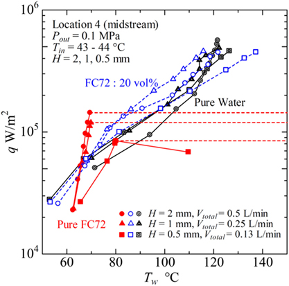
Figure 15. Typical heat transfer performance of immiscible mixtures in flow boiling for different gap sizes of rectangular channel.
Conclusion
Experiments on flow boiling of immiscible mixture of FC72 and water as the more-volatile and the less-volatile components, respectively, in horizontal narrow rectangular channels of gap sizes 2, 1, 0.5 mm were conducted. The following conclusions were obtained.
1. Most part of supplied heat is transferred to the more-volatile liquid with higher density as the latent heat of vaporization, once the temperature of mixture increased near its saturation temperature and boiling is initiated.
2. Generated flattened bubbles of more-volatile component has a positive effect on the heat transfer due to forced convection to less-volatile liquid by the contribution of nucleate boiling heat transfer to more-volatile liquid in addition to the increased liquid velocity and the agitation of less-volatile liquid flow by the generation of bubbles.
3. In nucleate boiling heat transfer to less volatile component, the bubble generation from more-volatile component substantially enhance the heat transfer by the extension of large flattened bubbles remaining a thin liquid film on the heating surface, however, the enhancement tends to the deterioration with the increase of heat flux by the extension of dry patches underneath these flattened bubbles.
4. Such a situation indicates the positive and negative effects of more-volatile component on the heat transfer to less-volatile component depending on the heat flux level and a gap size. The heat transfer deterioration can be reduced or eliminated by the reduction of flow rate of more-volatile liquid especially for smaller gaps. To obtain high heat transfer performance, there is an optimum composition of immiscible mixtures for each gap size or an optimum gap size for a given composition of mixtures.
5. Low value of CHF inherent in the pure more-volatile component is easily increased by the additional small flow rate of less-volatile liquid, while the increase of surface temperature from its level of pure more-volatile component is unavoidable.
6. The relation of heat flux versus surface temperature is changeable by using immiscible mixtures. Along the requirements from the surface to be cooled, both the level of CHF and the level of surface temperature can be varied by the selection of composition and/or the combination of immiscible mixtures.
7. For the heated channel with extreme small gap size, the very small concentration of more-volatile component or the use of more-volatile component with lower volatility is needed to prevent the heat transfer deterioration caused by the excessive growth of flattened bubbles.
8. The heat transfer characteristics for boiling of immiscible mixtures in narrow channels are more sensitive to the composition than those in a tube of normal size.
As regards the four advantageous heat transfer characteristics of immiscible mixtures in pool boiling described in the section of introduction, the following comments are possible for flow boiling in narrow channels. (i) Increase of CHF larger than pure less-volatile component is almost impossible because of the excessive generation of flattened bubbles from the less-volatile liquid. (ii) The reduction of surface temperature is possible because of the equilibrium temperature lower than either of saturation temperatures of the components. (iii) The substantial enhancement of heat transfer to the less-volatile liquid is possible by the generation of bubbles from more-volatile liquid except the case of high heat flux. However, as is the case of pool boiling, the enhanced heat transfer cannot easily be reflected to the values of heat transfer coefficient defined by the fluid temperature kept lower at near the equilibrium temperature. (iv) The increase of system pressure is possible keeping the liquid temperature lower than the saturation temperature of less-volatile component. Three advantages (ii)–(iv) observed in pool boiling are also true for the flow boiling in narrow rectangular channels tested here.
Nomenclature
| Bo | Bond number (–) |
| cp | Liquid isobaric specific heat (J/kg K) |
| di | Inner tube diameter or equivalent diameter (m) |
| Fr | Froude number (–) |
| G | Mass velocity (kg/m2 s) |
| g | Gravitational acceleration (m/s2) |
| hfg | Latent heat of vaporization (J/kg) |
| H | Gap size of channel between plates (m) |
| P | Pressure (Pa) |
| q | Heat flux (W/m2) |
| T | Temperature (°C) |
| Te | Equilibrium temperature of immiscible liquids (°C) |
| Tsat | Saturation temperature of component (°C) |
| Tw | Temperature of heating surface (°C) |
| um | Mean velocity of liquid and vapor mixture (m/s) |
| V | Volumetric flow rate (m3/s) |
| We | Weber number (–) |
| x1 | Quality for more-volatile component vapor only (–) |
| x | Quality for both component vapor (–) |
| z | Distance along the flow direction (m) |
| Greek symbols | |
| α | Heat transfer coefficient (W/m2 K) |
| ΔQ | Heat supplied between neighboring local positions (W) |
| ΔT | Temperature increment between neighboring local positions (K) |
| ∆Tsub | Degree of subcooling (K) |
| ρ | Density (kg/m3) |
| ξ | Ratio of heat transferred to more-volatile component to the total (–) |
| σ | Surface tension (N/m) |
| Suffixes | |
| 1 | More-volatile component |
| 2 | Less-volatile component |
| ave | Average value of both components |
| in | Inlet of heated test section |
| l | Liquid |
| out | Outlet of heated test section |
| total | Summation of values for more-volatile and less-volatile components |
| v | Vapor |
Author Contributions
YS designed and assembled the experimental equipment and analyzed data. DY conducted experiments and analysis of data. DF assisted the experiments and contributed to the preparation of manuscript. HO produced the concept of the present research and supervised the manuscript.
Conflict of Interest Statement
The authors declare that the research was conducted in the absence of any commercial or financial relationships that could be construed as a potential conflict of interest.
Acknowledgments
The present research was conducted under the research program of JSPS KAKENHI (Grant-in-Aid for Challenging Exploratory Research) Grant Number JP15K13887. The authors appreciate the support.
References
Abe, Y. (2005). “Heat management with phase change of self-rewetting fluids,” in Proceedings of the ASME 2005 International Mechanical Engineering Congress and Exposition, Orland, USA, 391–398. doi: 10.1115/IMECE2005-79174
Abubakar, A., Al-Wahaibi, Y., Al-Wahaibi, T., Al-Hashmi, A., Al-Ajmi, A., and Eshrati, M. (2015). Effect of low interfacial tension on flow patterns, pressure gradients and holdups of medium-viscosity oil/water flow in horizontal pipe. Exp. Therm. Fluid Sci. 68, 58–67. doi:10.1016/j.expthermflusci.2015.02.017
Baba, S., Ohtania, N., Kawanami, O., Inoue, K., and Ohta, H. (2012). Experiments on dominant force regimes in flow boiling using mini-tubes. Front. Heat Mass Transf. 3:043002. doi:10.5098/hmt.v3.4.3002
Bonilla, C. F., and Eisenbuerg, A. A. (1948). Heat transmission to boiling binary mixtures. Ind. Eng. Chem. 40, 1113–1122. doi:10.1021/ie50462a026
Bragg, J. R., and Westwater, J. W. (1970). “Film boiling of immiscible liquid mixture on a horizontal plate. Heat transfer 1970,” in Proceedings of the 4th International Heat Transfer Conference (France: Paris-Versailies), Vol. 6, B7.1. Available at: http://www.ihtcdigitallibrary.com/conferences/0c7302a61c102806,00982fb204779f3b,177ff1d00afeafea.html
Brauner, N. (2003). “Liquid-liquid two-phase flow systems,” in Modelling and Experimentation in Two-Phase Flow, eds V. Bertola, International Centre for Mechanical Sciences (Courses and Lectures), Vol. 450 (Vienna: Springer), 221–279.
Bulanov, N. V., and Gasanov, B. M. (2006). Peculiarities of boiling of emulsions with a low-boiling disperse phase. High Temp. 44, 267–282. doi:10.1007/s10740-006-0033-z
Filipczak, G., Troniewski, L., and Witczak, S. (2011). Pool boiling of liquid-liquid multiphase systems, evaporation, condensation and heat transfer. InTech 6, 123–150. doi:10.5772/24046
Fujita, Y., Ohta, H., Uchida, S., and Nishikawa, K. (1989). Nucleate boiling heat transfer and critical heat flux in narrow space between rectangular surfaces. Int. J. Heat Mass Transf. 31, 229–239. doi:10.1016/0017-9310(88)90004-X
Gorenflo, D., Gremer, F., Danger, E., and Luke, A. (2001). Pool boiling heat transfer to binary mixtures with miscibility gap: experimental results for a horizontal copper tube with 4.35 mm O.D. Exp. Therm. Fluid Sci. 25, 243–254. doi:10.1016/S0894-1777(01)00072-3
Hijikata, K., Mori, Y., and Ito, H. (1985). Experimental study on convective boiling of immiscible two-component mixture. Trans. Japan Soc. Mech. Eng. Ser. B 51, 1277–1284. (in Japanese). doi:10.1299/kikaib.51.1277
Kandlikar, S. G. (2006). “Flow boiling in minichannels and microchannels,” in Heat Transfer and Fluid Flow in Minichannels and Microchannels, Chap. 5, eds S. G. Kandlikar, S. Garimella, D. Li, S. Colin, and M. R. King (Elsevier), 175–226. doi:10.1016/B978-008044527-4/50007-4
Kandlikar, S. G., Colin, S., Peles, Y., Garimella, S., Pease, R. F., Brandner, J. J., et al. (2013). Heat transfer in microchannels – 2012 status and research needs. J. Heat Transf. 135, 091001-1–18. doi:10.1115/1.4024354
Kita, S., Ohnishi, S., Fukuyama, Y., and Ohta, H. (2014). “Improvement of nucleate boiling heat transfer characteristics by using immiscible mixtures,” in Proceedings of the 15th International Heat Transfer Conference, Kyoto, Japan, IHTC15-8941, 6261–6275. doi:10.1615/IHTC15.pbl.008941
Kobayashi, H., Ohtani, N., and Ohta, H. (2012). “Boiling heat transfer characteristics of immiscible liquid mixtures,” in Proceedings of the 9th International Conference on Heat Transfer, Fluid Mechanics and Thermodynamics, Malta, HEFAT2012, 771–776. Available at: https://repository.up.ac.za/dspace/bitstream/handle/2263/42977/kobayashi_boiling_2014.pdf?sequence=1
Lee, H. J., and Lee, S. Y. (2001). Heat transfer correlation for boiling flows in small rectangular horizontal channels with low aspect ratios. Int. J. Multiphase Flow 27, 2043–2062. doi:10.1016/S0301-9322(01)00054-4
Ohnishi, S., Ohta, H., Ohtani, N., Fukuyama, Y., and Kobayashi, H. (2013). Boiling heat transfer by nucleate boiling of immiscible liquids. Interfacial Phenom. Heat Transf. 1, 63–83. doi:10.1615/InterfacPhenomHeatTransfer.2013007205
Ohta, H. (2003). Microgravity heat transfer in flow boiling. Adv. Heat Transf. 37, 1–76. doi:10.1016/S0065-2717(03)37001-7
Ohta, H., Inoue, K., Ando, M., and Watanabe, K. (2009). Experimental investigation on observed scattering in heat transfer characteristics for flow boiling in a small diameter tube. Heat Transf. Eng. 30, 19–27. doi:10.1080/01457630802290080
Ohta, H., Iwata, K., Yamamoto, D., and Shinmoto, Y. (2015). “Superior heat transfer characteristics in boiling of immiscible mixtures,” in Proceedings of the 26th International Symposium on Transport Phenomena, Leoben, Austria, Vol. 89.
Ohta, H., Shinmoto, Y., Yamamoto, D., and Iwata, K. (2016). “Boiling of immiscible mixtures for cooling of electronics,” in Electronics Cooling, Chap. 2, ed. S. M. Sohel Murshed (InTech), 11–29. doi:10.5772/62341
Roesle, M. L., and Kulacki, F. A. (2012). An experimental study of boiling in dilute emulsions. Part A: heat transfer. Int. J. Heat Mass Transf. 55, 2160–2165. doi:10.1016/j.ijheatmasstransfer.2011.12.020
Sakai, T., Yoshii, S., Kajimoto, K., Kobayashi, H., Shinmoto, Y., and Ohta, H. (2010). “Heat transfer enhancement observed in nucleate boiling of alcohol aqueous solutions at very low concentration,” in Proceedings of the 14th International Heat Transfer Conference, Washington, DC, Vol. 2010. IHTC14-22737. doi:10.1115/IHTC14-22737
Shiina, K., and Sakaguchi, S. (1997). Boiling heat transfer characteristics in liquid-liquid direct contact parallel flow of immiscible liquid: heat transfer flow pattern and empirical correlation. Trans. Japan Soc. Mech. Eng. Ser. B 63, 970–978. (in Japanese). doi:10.1002/(SICI)1520-6556(1997)26:8<493:AID-HTJ1>3.0.CO;2-R
Sump, G. D., and Westwater, J. W. (1979). Boiling heat transfer from a tube to immiscible liquid-liquid mixtures. Int. J. Heat Mass Transf. 14, 767–779. doi:10.1016/0017-9310(71)90106-2
Van Stralen, S. J. D. (1956). Heat transfer to boiling binary liquid mixtures at atmospheric and subatmospheric pressures. Chem. Eng. Sci. 5, 290–296. doi:10.1016/0009-2509(56)80004-3
Vochten, R., and Petre, G. (2005). Study of the heat of reversible adsorption at the air-solution interface. J. Colloid Interface Sci. 42, 320–327. doi:10.1016/0021-9797(73)90295-6
Willingham, T. C., and Mudawar, I. (1992). Channel height effects on forced-convection boiling and critical heat flux from a linear array of discrete heat sources. Int. J. Heat Mass Transf. 8, 1865–1880. doi:10.1016/0017-9310(92)90190-4
Keywords: immiscible mixture, flow boiling, narrow channel, narrow gap, heat transfer enhancement, heat transfer deterioratio
Citation: Shinmoto Y, Yamamoto D, Fujii D and Ohta H (2017) Heat Transfer Characteristics during Boiling of Immiscible Liquids Flowing in Narrow Rectangular Heated Channels. Front. Mech. Eng. 3:16. doi: 10.3389/fmech.2017.00016
Received: 09 March 2017; Accepted: 23 October 2017;
Published: 21 November 2017
Edited by:
Satish Kumar, Georgia Institute of Technology, United StatesReviewed by:
Alexander S. Rattner, Pennsylvania State University, United StatesAmy Rachel Betz, Kansas State University, United States
Copyright: © 2017 Shinmoto, Yamamoto, Fujii and Ohta. This is an open-access article distributed under the terms of the Creative Commons Attribution License (CC BY). The use, distribution or reproduction in other forums is permitted, provided the original author(s) or licensor are credited and that the original publication in this journal is cited, in accordance with accepted academic practice. No use, distribution or reproduction is permitted which does not comply with these terms.
*Correspondence: Haruhiko Ohta, b2h0YUBhZXJvLmt5dXNodS11LmFjLmpw