- Department of Mechanical Engineering, University of Cape Town, Cape Town, South Africa
This paper presents the exergy analysis and optimization of the Stirling engine, which has enormous potential for use in the renewable energy industry as it is quiet, efficient, and can operate with a variety of different heat sources and, therefore, has multi-fuel capabilities. This work aims to present a method that can be used by a Stirling engine designer to quickly and efficiently find near-optimal or optimal Stirling engine geometry and operating conditions. The model applies the exergy analysis methodology to the ideal-adiabatic Stirling engine model. In the past, this analysis technique has only been applied to highly idealized Stirling cycle models and this study shows its use in the realm of Stirling cycle optimization when applied to a more complex model. The implicit filtering optimization algorithm is used to optimize the engine as it quickly and efficiently computes the optimal geometry and operating frequency that gives maximum net-work output at a fixed energy input. A numerical example of a 1,000 cm3 engine is presented, where the geometry and operating frequency of the engine are optimized for four different regenerator mesh types, varying heater inlet temperature and a fixed energy input of 15 kW. The WN200 mesh is seen to perform best of the four mesh types analyzed, giving the greatest net-work output and efficiency. The optimal values of several different engine parameters are presented in the work. It is shown that the net-work output and efficiency increase with increasing heater inlet temperature. The optimal dead-volume ratio, swept volume ratio, operating frequency, and phase angle are all shown to decrease with increasing heater inlet temperature. In terms of the heat exchanger geometry, the heater and cooler tubes are seen to decrease in size and the cooler and heater effectiveness is seen to decrease with increasing heater temperature, whereas the regenerator is seen to increase in size and effectiveness. In terms of the regenerator mesh type, it was found that the WN200 mesh gave a shorter regenerator with greater cross-sectional flow area which gave a smaller pressure drop.
Introduction
The Stirling engine was invented by Rev. Robert Stirling some 200 years ago, at the time the engine received some attention and saw commercial use (Stirling, 1816). However, at the time the rapid development of the internal combustion engine quickly overshadowed the Stirling engine. In recent years, there has been renewed interest in the Stirling engine, especially with the rise in interest in renewable energy technology. Stirling engines are poised to play a pivotal role in this industry as they are quiet, have multi-fuel capabilities, produce little pollution and are efficient (Thombare and Verma, 2008). Furthermore, the Stirling engine is categorized as a Reitlinger class cycle, which means it can theoretically achieve Carnot Efficiency (Senft, 1998). The current uncertainty over the future availability of fossil fuels and the imminent threat of climate change means that new sources of energy need to be utilized (Ellabban et al., 2014). The Stirling engine is a prime candidate for use with renewable sources of energy as the engine operates through a closed thermodynamic cycle that can utilize any heat source. The Stirling engine has also been cited as being the most economically viable solar converter in the range of 5–100 kWe (Kongtragool and Wongwises, 2003).
There are a variety of different approaches to Stirling engine modeling and there exist several different orders of models (Dyson et al., 2004). These models are of varying complexity and there have been several studies that analyze, compare, and discuss the different models available. Initially, Stirling engines were modeled with isothermal working spaces; however, in recent times the working spaces have been modeled as having finite rates of heat transfer, or as being adiabatic. The analysis conducted by Finkelstein was the first of its kind and represented a major advancement in Stirling engine analysis when he considered non-isothermal working spaces (Finkelstein, 1960). Subsequently, Urieli and Berchowitz developed the ideal adiabatic model. This model more accurately predicts performance as in real Stirling engines the cylinders are not designed for heat transfer (Berchowitz and Urieli, 1984). In these models, a variety of losses are quantified, and included in the analysis to predict the output of a real engine operating at specified conditions (Walker, 1980). In the most recent study, a model with polytropic working spaces has been developed (Babaelahi and Sayyaadi, 2015). A significant portion of Stirling cycle optimization studies have moved toward numerical simulations that in the past were too computationally expensive to use for optimization purposes. However, with the extensive work carried out by Berchowitz and Urieli (1984), the models have been significantly sped up, and more than 30 years later computing speed has also drastically increased. A Stirling engine simulation that originally took 10 min to run now takes seconds. There have been several studies that have aimed to predict and optimize engine performance using numerical models. The study conducted by Timoumi et al. (2008) presented a new model of the Stirling cycle. The model presented was used to optimize the GPU-3 Stirling engine and a medium temperature difference solarpowered engine (Tlili et al., 2008). The study conducted by Campos et al. (2012), used a similar model to maximize the non-dimensional engine efficiency at specified conditions. The effect that changing parameters had on performance was also analyzed and it was found that the engine performance is robust to changes in some parameters. Senft used the classical Schmidt analysis and conducted an analysis that looked to find the optimum engine geometry of a Stirling engine (Senft, 2002). Other studies have also looked to analyze the second-order non-ideal adiabatic model using a multi-objective optimization approach (Toghyani et al., 2014). The analysis optimized the engine in terms efficiency and pressure drop, a Pareto frontier of optimal solutions is presented.
There have been several studies that have applied the exergy analysis methodology to ideal Stirling cycle models. The study conducted by Martaj et al. (2006), applied the exergetic, energetic and entropic analysis techniques to the Stirling cycle to optimize the performance. The same authors in a separate study analyzed and optimized a low temperature difference Stirling engine at steady state operation (Martaj et al., 2007). de Boer (2003) showed the importance of including pressure drop in his analysis of the Stirling engine regenerator, where he proved the maximum achievable efficiency for a Stirling cycle engine is half of Carnot efficiency. The analysis by Wu et al. (1998) formulated criteria to optimize the heat transfer area in the heater and cooler. Similarly, Costea and Feidt (1998) conducted an analysis looking at the irreversibility and the effects that the heat exchanger area had on Stirling engine performance. These analyses and optimizations usually begin with highly idealized models of the Stirling cycle which is problematic as they do not necessarily accurately model the Stirling cycle. There have been several studies that have looked at Stirling engine power density. Also, the dead-volume ratio has been seen to have a significant effect on performance, especially when adiabatic working spaces are assumed (Wills and Bello-Ochende, 2016). The effects of dead-volume have also been mentioned by several authors as negatively affecting the power output of Stirling engines (Kongtragool and Wongwises, 2006; Puech and Tishkova, 2011). These studies have analyzed how the dead-volume negatively affects the cycle efficiency and power output. Several studies have looked to optimize the power density of the Stirling engine as the engine size is of economic interest (Erbay and Yavuz, 1997, 1999). These analyses optimized the device in terms of maximum power density as this results in engines with good power density and high efficiency.
There have been many studies that have optimized power cycles using exergy analysis methodology. Where exergy is defined as the energy that is available to do work. The Gouy–Stodola theorem, which describes the relationship between reversible work , irreversible work , entropy generation and environmental temperature T0 (Bejan, 1996), can be seen below as Eq. 1.
The development of this equation was a major advancement in the thermodynamics of the time, and the expression shows that the rate of entropy generation is directly proportional to the rate at which work is destroyed. While using this methodology, it has been emphasized that it is crucial to optimize the system in its entirety, rather than as individual components (Bejan, 2006). This is done, as spreading the irreversibility over the entire system rather than minimizing it in individual components results in a truly optimized system.
This paper presents a novel approach to modeling the losses and optimizing the alpha type Stirling engine, which involves the application of exergy analysis methodology to the ideal adiabatic model of the Stirling cycle. The model incorporates the irreversibility due to heat transfer through a finite temperature difference, pressure drops and conductive thermal bridging loss. The model presented is used with the implicit filtering algorithm to optimize a 1,000 cm3 Stirling engine for maximum power production with four different regenerator mesh types and a fixed energy input. In the analysis, the working fluid is assumed to be an ideal gas and a finite heat capacity rate is assumed in the heater and cooler, the number of heater and cooler tubes are also fixed.
Physical Model
The methodology used to optimize the 1,000 cm3 alpha type Stirling engine for maximum work output with a fixed energy input is presented in this section. The working fluid is assumed to be pressurized air which behaves as an ideal gas. The heater and cooler external fluids are assumed to have finite heat capacity rates, and four different regenerator mesh types are used in this analysis.
Model Description
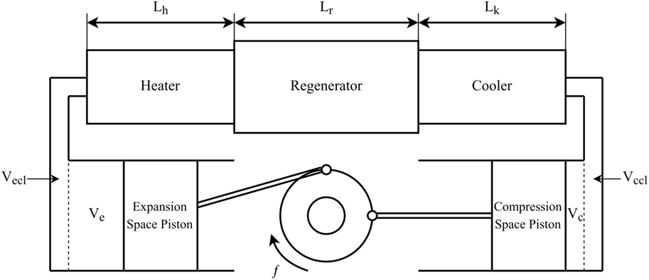
A diagram of the alpha type Stirling engine used in the analysis can be seen as Figure 1. In this diagram, the operating frequency f, volume V, and heater, cooler, and regenerator lengths L are shown.
The expressions for the compression and expansion space volumes are Eqs 2 and 3. Eq. 2 calculates the volume in the compression space Vc using the clearance volume Vccl, swept volume Vc,swept, and the crank angle θ.
Similarly, Eq. 3 calculates the volume in the expansion space using the clearance volume Vecl, swept volume Ve,swept, crank angle θ, and phase difference α.
Equations are required to determine the volumes from the geometric variables for the heat exchangers. Equations 4–9 are the equations for the volume V and area A of the cooler, heater and regenerator, respectively.
Equations 4 and 5 define the volume Vk and surface area Ak in the cooler. These equations use the number of cooler tubes Nk, cooler length Lk and cooler tube diameter Dk.
Equations 6 and 7 define the volume Vh and surface area Ah of the heater. These equations use the number of heater tubes Nh, heater length Lh and heater tube diameter Dh.
Equations 8 and 9 define the volume Vr and surface area Ar in the regenerator. These equations use the mesh porosity ε, regenerator length Lr, regenerator diameter Dr, and hydraulic diameter dhyd.
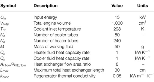
Figure 1 shows the different engine variables. To model the engine, some of the variables are fixed, and Table 1 gives these variables and their values. The values are chosen based on an idealized model of the Stirling engine, and the number of heater and cooler tubes was chosen based on real Stirling engines (Timoumi et al., 2008). The number of heater tubes is far lower than the number of cooler tubes; this is because decreasing the temperature of the working fluid in the cooler has a greater effect on engine performance than increasing the temperature of the working fluid in the heater. Another reason there are fewer tubes in the heater is that in real Stirling engines the heater may have combustion products flowing through it. Depending on the fuel source this may foul the heat exchanger, and therefore the spacing of the tubes is important to facilitate cleaning. The cooler usually has water flowing through it which means it would not foul nearly as quickly as the heater.
Along with these fixed parameters, four different mesh types are used in the optimization. The mesh types and their properties can be seen in Table 2.

Table 2. Table of regenerator mesh dimensions (Tanaka et al., 1990).
Mathematical Model
The following section presents and describes the equations used to model the alpha type Stirling engine which is optimized in this study. First, the model and the ideal adiabatic model of the Stirling cycle are presented. Following this the equations that describe the heat transfer, flow friction and thermal bridging loss are presented and explained. Finally, the exergy and rate of entropy generation equations are introduced and the method of solution is described.
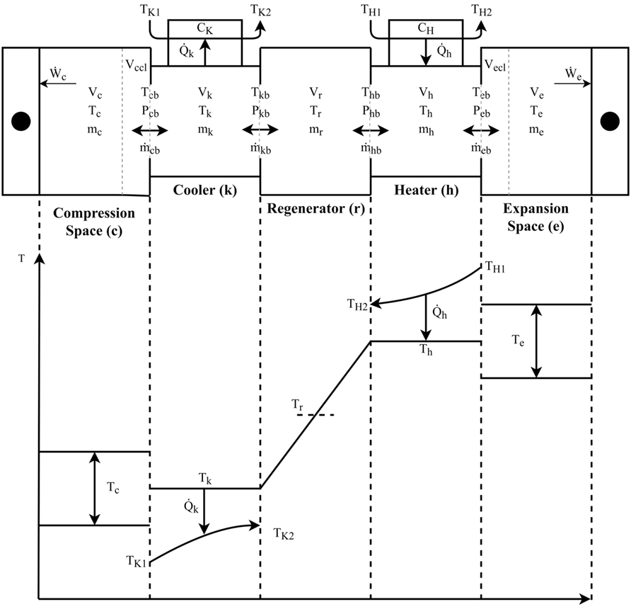
The model outlined assumes finite heat capacity rates in the heater and cooler. The compartment temperature diagram shows the different thermodynamic properties and temperature in each compartment, seen as Figure 2.
Figure 2 is used as a means of graphically showing and defining different thermodynamic properties in the engine compartments and energy flows. The properties shown are pressure P, temperature T, and volume V. The compartments are the compression space c, cooler k, regenerator r, heater h, and expansion space e. The compartment interfaces are the compression space to cooler interface cb, the cooler to regenerator interface, the regenerator to heater interface and the heater to expansion space interface. All the equations presented in this section can be understood using the diagram and the knowledge that R is the ideal gas constant, Cp is the constant pressure specific heat, CV is the constant volume specific heat and γ is the ratio of specific heats.
Ideal Adiabatic Model
The ideal adiabatic model was developed by Urieli and Berchowitz as a means of more accurately modeling the real Stirling cycle. At the time of the development of these models the iterative schemes took too long to solve, to make the model useful in the optimization of Stirling engine geometry. However, due to advances in computing and better models the solutions are arrived at in seconds rather than minutes, making these numerical models suitable for optimization purposes.
The full derivation of the equations is not presented but the equations are listed and briefly explained. To see the complete derivation of the equations, see the book by Urieli and Berchowitz (Berchowitz and Urieli, 1984), or the online resources maintained by Urieli (2017).
The ideal adiabatic model assumes that there is negligible pressure variation throughout the engine. Therefore, Eq. 10 describes the pressure P in all the engine compartments.
Assuming that the total mass of working fluid in the device is the sum of the masses of working fluid in each component yields Eq. 11.
Assuming, the mass of working fluid remains constant, yields Eq. 12.
For the cooler, regenerator and heater the volume and temperature are assumed to be constant. Therefore, the mass differential is defined as Eqs 13–15.
Substituting Eqs 13–15 into Eq. 12 and rearranging, yields Eq. 16.
Applying the mathematical expression for the first law to a generalized cell of working space yields Eq. 17.
Rearranging Eq. 17 to give the change in mass in the compression and expansion spaces yields Eqs 18 and 19.
Substituting Eqs 18 and 19 into Eq. 16 and rearranging yields Eq. 20.
Defining the temperature differentials in the compression and expansion spaces, yields Eqs 21 and 22.
The mass flows through the compartment boundaries are defined as Eqs 23–26.
The conditional temperatures which depend on the direction of fluid flow in the heater and cooler are Eqs 27 and 28.
The energy equations that describe the heat absorbed and rejected in the cooler, regenerator, and heater are Eqs 29–31.
The energy equations which describe the work output of the cycle are Eqs 32 and 33.
Flow Losses
When calculating the pressure drop ΔP in the heat exchangers, the Reynolds friction factor fr approach is used as this results in the change of pressure drop sign with change in flow direction (Berchowitz and Urieli, 1984). The Reynolds friction factor is defined as the Darcy friction factor fD multiplied by the Reynolds number Re.
Equation 34 is used to calculate the pressure drop ΔP, where viscosity μ, gas velocity u, volume V, flow area Aflow and hydraulic diameter dhyd are used.
Equation 35 is the Darcy friction factor fD in the regenerator and is calculated using the maximum Reynolds number Remax (Tanaka et al., 1990).
In the case of the cooler and the heater unidirectional smooth pipe flow relations are used to calculate the Darcy friction factor fD (Joseph and Yang, 2010). These relations are for flow in the turbulent regime, seen as Eqs 36 and 37.
Heat Transfer Relations
Equations 38 and 39 are for the Nusselt number Nu and effectiveness ε of the regenerator (Tanaka et al., 1990).
Equation 40 is the Gnielinski relation which is used to calculate the Nusselt number in the heater and the cooler (Gnielinski, 1975). This is then in turn used to calculate the heat transfer coefficient h in the heater and the cooler.
Assuming, the overall heat transfer coefficient U in the heater and the cooler is equal to the heat transfer coefficient h on the inside of the tubes, this in turn is used to compute the number of transfer units (NTU), seen as Eq. 41.
This is used to compute the NTU in the heater and cooler, which in turn is used to compute the effectiveness ε in the heater and cooler, seen as Eq. 42.
Conductive Thermal Bridging Loss
The conductive thermal bridging loss is included in the analysis, as heat is conducted between the hot and cold parts of the engine (Ahmadi et al., 2016). Equation 43 quantifies the conductive thermal bridging loss, which is calculated using the regenerator thermal conductivity kcond, the conduction area Acond, the regenerator length Lr, and the heater temperature Th and cooler temperature Tk.
Exergy Analysis
Defining the exergy of the engine yields Eq. 44. This equation is used to calculate the work output , using the entering exergy , the leaving exergy , and the irreversibility rate which is .
Defining the second law mathematically in terms of crank angle θ, yields Eq. 45.
Therefore, defining the entropy generation per cycle Sgen and assuming the mass flow through the heat exchangers is constant yields Eq. 46.
Defining the difference in entropy between the entering and leaving gas Sout − Sin yields Eq. 47.
Substituting Eq. 47 into 46 yields the entropy generated per cycle which is Eq. 48.
Therefore, the rate of entropy generation is defined as Eq. 49.
Since the flow is reversing the entropy generation due to pressure drop can be written as Eq. 50.
The equation for rate of entropy generation in the heater is defined as Eq. 51.
The equation for rate of entropy generation in the cooler is defined as Eq. 52.
Using the definition of effectiveness ε to define the temperatures leaving the regenerator is seen as Eq. 53.
Therefore, the equation for the rate of entropy generation in the regenerator is defined as Eq. 54.
Assuming the rate of entropy generation in the expansion and compression spaces is negligible compared to the entropy generation rate in the heat exchangers , the total rate of entropy generation can be calculated by summing the rates of entropy generation in the heater , regenerator and cooler , seen as Eq. 55.
Defining the objective function by substituting Eqs 51, 52, and 55 into Eq. 55 and assuming all the heat exchangers are perfectly adiabatic, yields Eq. 56.
Equation 56 is the objective function which gives the work output of the engine. This function is the function that is used to optimize the Stirling engine geometry.
Method of Solution
The solution is obtained using three iterative loops. The outer loop computes the energy input; the middle loop computes the temperature difference for adequate heat transfer in the cooler, and the inner loop computes the solution to the ideal adiabatic model equations. The middle loop takes the values for mass flow rate and energy from the inner loop, and uses these to compute the gas temperature in the heater and the cooler. This value is then compared to the previous iteration and if it is within the specified tolerance convergence has been reached. The inner loop computes the solution to the ideal adiabatic model as a closed form solution does not exist and, therefore, an iterative method is required. To quickly and effectively find the solution, two different iterative methods are used in the analysis. The Runge–Kutta method is used for the first four iterations and following this the Adams–Bashforth method is used. This reduces the computation time as the Adams–Bashforth method does not require the computation of intermediate steps but only uses previously computed derivatives, resulting in greater computational efficiency (Faires and Burden, 2010). This scheme is run until convergence is reached between the start and end temperatures in the compression and expansion spaces. Once this convergence is reached the mass flow rates and energy values are used in the outer loop to compute the new heater and cooler gas temperatures. This scheme is run within the outer loop which changes the engine operating frequency until the desired energy input is obtained.
Optimization Algorithm
To optimize the geometry and operating frequency of the Stirling engine, the problem is initially formulated as a bounded constraint minimization problem. The standard form of such a problem is Eq. 57.
where
The function to be minimized is Eq. 57 which is the objective function for the net-work output of the engine. This optimization is achieved by minimizing the negative of the work output. However, the equations outlined in the previous section exhibit several characteristics that make optimization of the objective function unsuitable for classic gradient based algorithms. The problems that make the function unsuitable for gradient-based optimization schemes are listed below:
1. The function is discontinuous.
2. The function is non-smooth.
3. There is some degree of numerical noise.
4. Little is known about the function space.
5. Each function evaluation is expensive.
The function described exhibits these characteristics, and therefore a specialized algorithm is required. The algorithm of choice is the implicit filtering scheme originally developed by Professor Kelley and colleagues (Kelley, 1999, 2011). This algorithm was developed for noisy problems where derivative information is too difficult to obtain or is inaccurate. In its simplest form, the method developed by Kelley is the steepest descent algorithm with difference gradients that progressively shrink as the solution moves toward the minimum. The quasi-Newton method used is the Broyden–Fletcher–Shanno–Goldfarb update. This update allows for the inverse Hessian to be approximated quickly and efficiently.
Results and Discussion of Results
The analysis and optimization procedure found the optimal geometry and engine speed that gave maximum net-work output at the fixed heat input. The variables which have been optimized are the total heat exchanger length, dead-volume ratio, regenerator length, heater tube length, cooler tube length, compression space to expansion space volume ratio, phase difference, and the operating frequency.
Work Output and Efficiency
Figure 3 is a plot of the maximum net-work output, minimum total irreversibility rate, and absorbed energy versus heater inlet temperature for the four different mesh types.
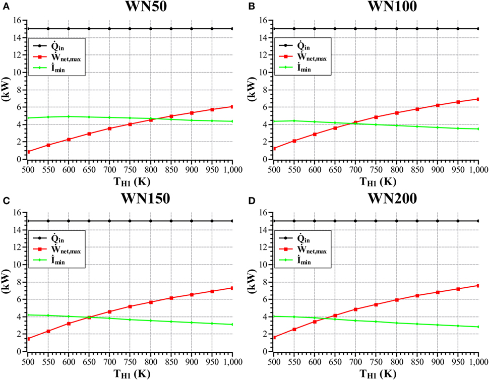
Figure 3. Maximum network output, minimum total irreversibility rate, and absorbed energy versus heater inlet temperature for the WN50 (A), WN100 (B), WN150 (C), and WN200 (D) mesh types.
Figure 3 shows that as the heater inlet temperature increases the maximum net-work output increases and the minimum irreversibility rate decreases. The reason is that the optimal engine operating frequency decreases with increasing heater inlet temperature, thus decreasing the irreversibility rate. The optimal regenerator length is also seen to increase, along with the regenerator effectiveness which decreases the heat transfer irreversibility in the regenerator. This is seen to be most pronounced in the WN200 mesh as this mesh is the finest mesh thus offering the greatest heat transfer area per unit volume, whereas the WN50 offers the lowest heat transfer area per unit volume.
Figures 4 is a plot of maximum net-work output and maximum thermal efficiency versus heater inlet temperature.
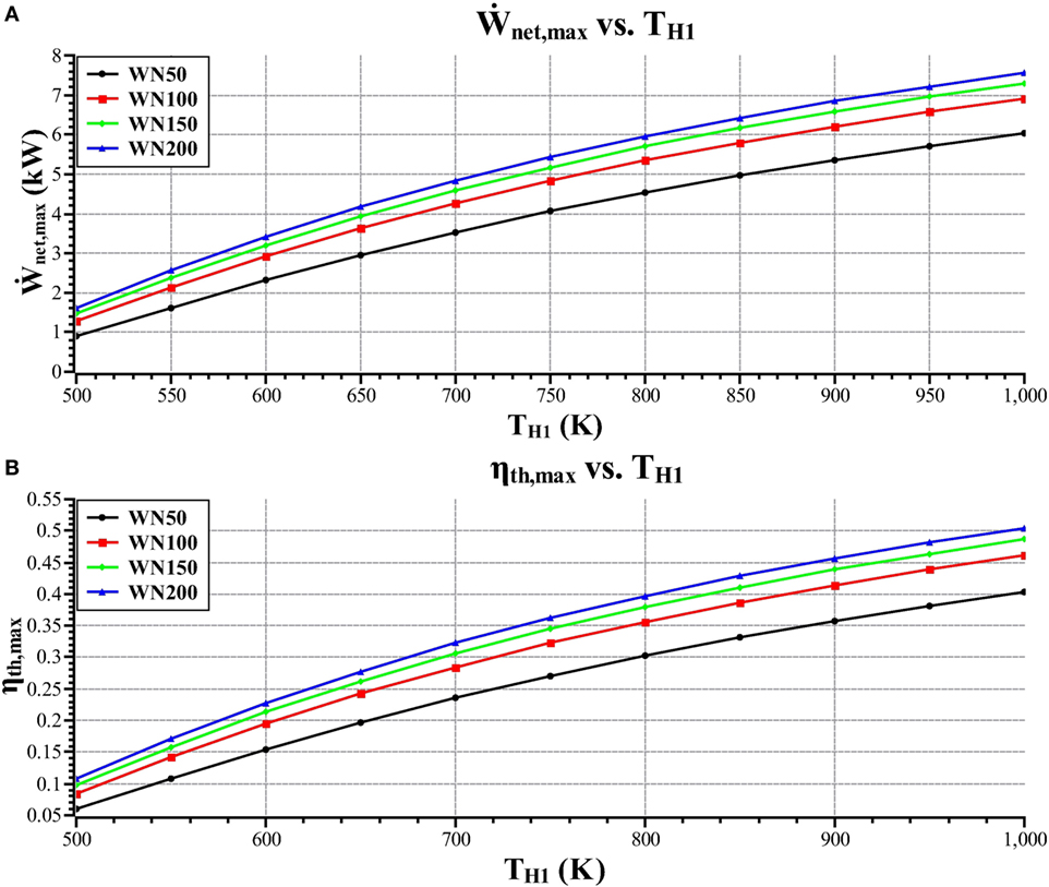
Figure 4. Maximum net-work output (A) and maximum thermal efficiency (B) versus heater inlet temperature.
The maximum efficiency plot seen as Figure 4B follows from the maximum net-work output plot seen as Figure 4A. From these figures, it is seen that as the heater inlet temperature increases, the maximum net-work output and the maximum efficiency increases. It can also be seen that the WN200 mesh gives greater performance than the other mesh types. Whereas, the WN50 gives the poorest performance. The reason for this is that the WN200 mesh is the finest mesh which gives the greatest surface area per unit volume which results in a mesh that gives the lowest irreversibility rate in the regenerator. The WN200 mesh also results in the smallest regenerator in terms of void volume which means that more of the available dead-volume can be allocated to the heater and the cooler. This gives larger heater and cooler tubes having greater surface area and a lower pressure drop, this results in lower irreversibility rates in these components and when coupled with increased regenerator performance gives greater overall engine performance.
Allocation of Volume
Figure 5 is a plot of optimal dead-volume ratio versus heater inlet temperature.
Figure 5 shows that the optimal dead-volume ratio decreases with increasing heater inlet temperature. The reason for this is that with increasing temperature difference between the heater and cooler the optimal dead-volume ratio decreases. In the case of the ideal adiabatic model, there exists an optimal dead-volume ratio for maximum net-work output and as the dead-volume ratio tends toward one the cycle efficiency increases toward Carnot efficiency (Wills and Bello-Ochende, 2016). These two different design points play an integral part in the optimization of the Stirling cycle as the optimal dead-volume ratio is where the net-work output and the efficiency are balanced with the dead-volume that gives the optimal engine geometry for minimum irreversibility rate. Upon further inspection of the results, it can be deduced that there exist design points that give lower irreversibility rates. However, the volume allocation is not near the optimal thus giving poorer overall engine performance. Therefore, the irreversibility rate needs to be minimized while also optimizing the allocation of volume.
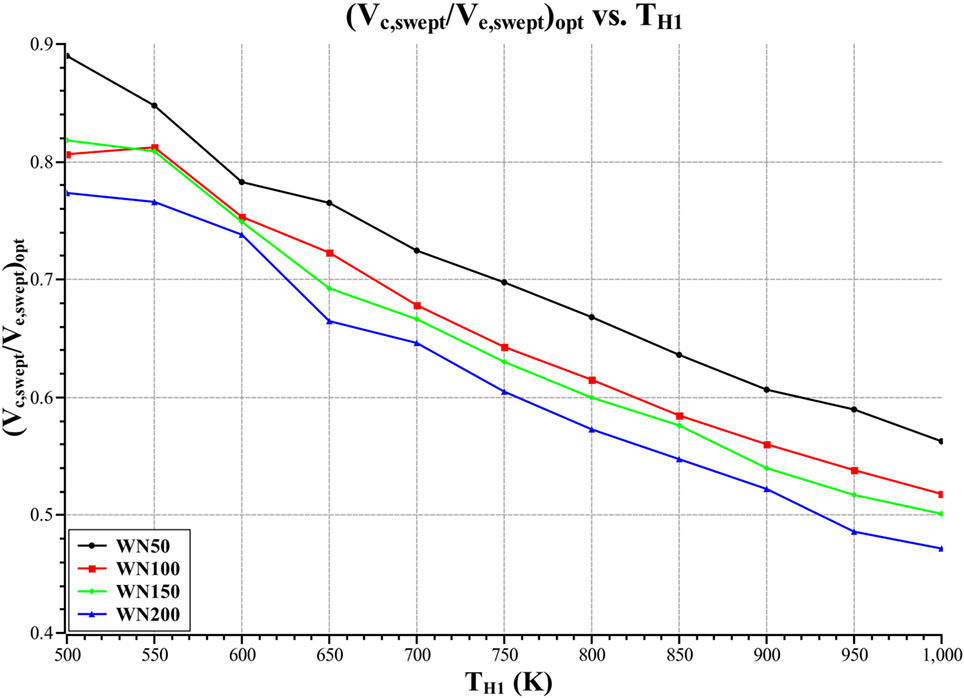
Figure 6 is a plot of optimal swept volume ratio versus heater inlet temperature.
Figure 6 shows that the optimal swept volume ratio is seen to decrease with increasing heater inlet temperature. The reason for this is that the heater to cooler temperature ratio increases with increasing heater inlet temperature. When analyzing the ideal model, the optimal ratio of compression space swept volume to expansion space swept volume is always less than one and decreases with increasing heater to cooler temperature ratio. This is because as the heater to cooler temperature ratio increases the portion of heat transferred out of the cooler decreases thus less compression space work is required as this amount of work is directly proportional to the heat load in the cooler. This gives a smaller compression space relative to the expansion space as it reduces the compression space work input relative to the expansion space work output.
Heat Exchanger Geometry
The sizing of the heat exchangers has a significant effect on the performance of the Stirling engine. The following plots show the optimal values for heat exchanger geometry at the different heater inlet temperatures that correspond to optimal engine performance at a fixed heat input.
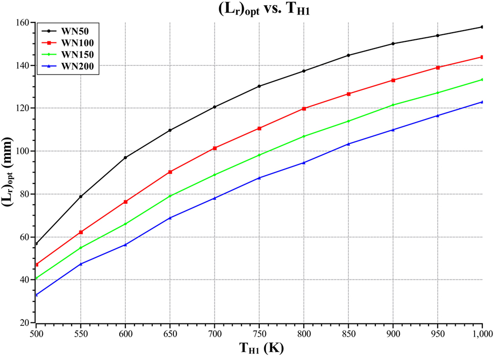
Figure 7 is a plot of optimal regenerator length versus heater inlet temperature for the four different mesh types.
Figure 7 shows that the optimal regenerator length increases with increasing heater inlet temperature. It can also be seen that the WN200 mesh type yields the shortest regenerator and the WN50 mesh yields the longest regenerator. The reason for this is that the WN200 mesh offers the greatest surface area per unit volume and the WN50 mesh yields the lowest surface area per unit volume. Therefore, the optimal mesh length for the case of the WN200 mesh type is significantly shorter than for the WN50 mesh type. This significantly affects engine performance as a smaller regenerator has less void volume, which means more of the available dead-volume can be allocated to the cooler and heater increasing the performance of these components. The shorter regenerator also gives a smaller pressure drop which results in the optimal operating frequency being greater which means that more cycles are completed per unit time thus producing a higher net-work output.
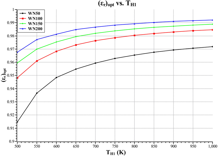
Figure 8 is a plot of optimal regenerator effectiveness versus heater inlet temperature for the four different mesh types.
Figure 8 shows that the WN200 mesh gives the greatest optimal regenerator effectiveness, the reason for this is that the WN200 mesh is the finest mesh and, therefore, gives the greatest heat transfer area per unit volume. This positively affects the engine performance as the higher effectiveness of the regenerator reduces the heat transfer irreversibility, thus decreasing the total irreversibility rate. The WN200 mesh also gives the lowest pressure drop of all the mesh types, this means that the engine with the WN200 mesh type will operate at a higher frequency which increases the work output of the engine. The reason for the lower pressure drop is that the WN200 mesh type results in a wider shorter optimal regenerator, thus decreasing pressure drop when compared to the WN50 mesh which is longer.
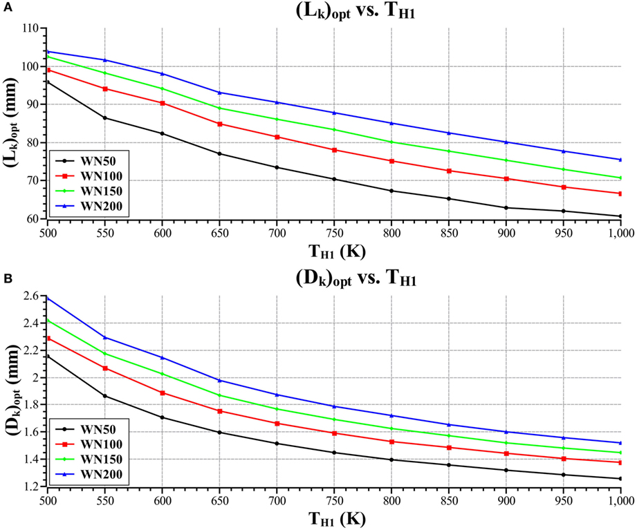
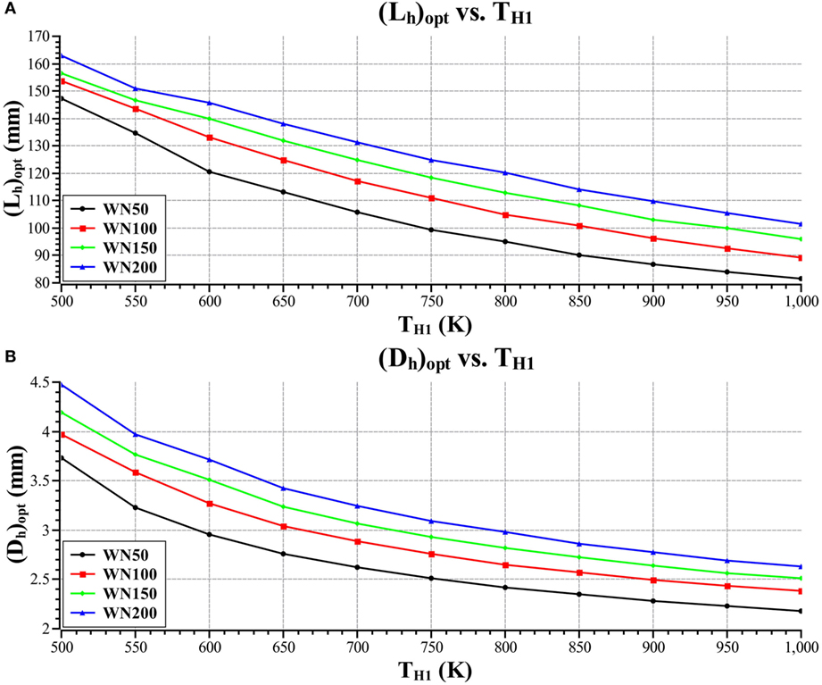
Figure 9 is a plot of optimal cooler tube length and diameter versus heater inlet temperature for the four different mesh types.
Figure 10 is a plot of optimal heater tube length and diameter versus heater inlet temperature for the four different mesh types.
Figure 11 is a plot of optimal heater effectiveness and optimal cooler effectiveness versus heater inlet temperature for the four different mesh types.
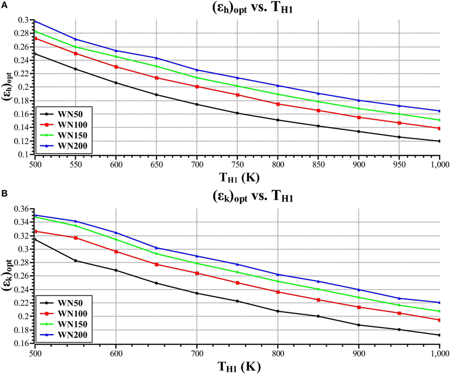
Figure 11. Optimal heater effectiveness (A) and cooler effectiveness (B) versus heater inlet temperature.
Figures 9 and 10 show that the cooler and heater tube lengths and diameters decrease with increasing heater inlet temperature. The reason for this is that as the heater inlet temperature increases, the optimal operating frequency decreases; thus decreasing the working fluid mass flow rate through the heat exchangers. Due to this decrease in flow rate, the regenerator pressure drop decreases which results in the regenerator length increasing and diameter decreasing, this increases the regenerator effectiveness which decreases the irreversibility rate in the regenerator. This reduces the dead-volume that can be allocated to the other heat exchangers as the void volume of the regenerator increases with increasing regenerator length, and the optimal dead-volume ratio also decreases with increasing heater inlet temperature. Therefore, the cooler and heater tubes decrease in length and diameter as the available dead-volume decreases and the void volume of the regenerator increases. This results in a decrease in heat exchanger surface area that affects the heat transfer performance.
Figure 11 shows that the cooler and heater effectiveness decreases with increasing heater inlet temperature. The reason for this decrease in effectiveness is that the optimal engine speed decreases with increasing heater inlet temperature, this decreases the heat transfer coefficient in the heater and the surface area in the heater also decreases as the optimal dead-volume ratio decreases and the void volume of the regenerator increases. This decreases the NTU in the heater, resulting in a decrease in the effectiveness.
When comparing Figures 9–11, it is seen that the cooler has a greater surface area and a greater effectiveness than the heater and this is because there are more cooler tubes than heater tubes. This is specified as the performance of the cooler has a far more pronounced effect on engine performance than the heater. Decreasing the working fluid temperature in the cooler has a comparatively greater effect on efficiency than increasing the working fluid temperature in the heater, which can easily be illustrated by simply analyzing the expression for Carnot efficiency.
Operating Frequency
This study differs from many other studies as the optimal engine operating frequency is calculated, whereas in other studies the operating frequency is specified. This approach allows for the operating frequency to be optimized with the other variables to give optimal engine performance.
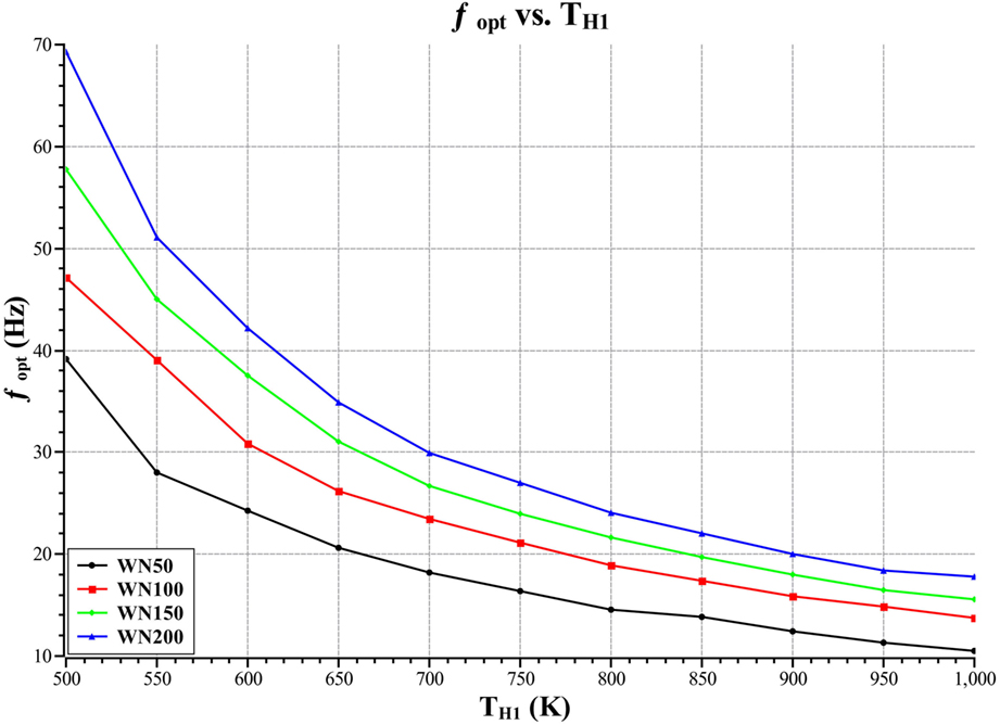
Figure 12 is a plot of optimal operating frequency versus heater inlet temperature for the four different regenerator mesh types.
Figure 12 shows that the optimal operating frequency decreases with increasing heater inlet temperature. The reason for this is that as the heater inlet temperature increases the amount of energy absorbed per cycle increases, thus the required operating frequency to absorb the specified input energy decreases. The plot also shows that the WN200 mesh type gives a higher optimal operating frequency than the WN50 mesh type. The difference in operating frequency for each mesh type is because the Reynolds number in the regenerator for a given mass flow rate is greater for the WN50 mesh type than the WN200 mesh type. This results in the optimal operating frequency being higher for the WN200 mesh type as the optimal Reynolds number in the regenerator is at a higher operating frequency for the WN200 mesh type than the WN50 mesh type. This increased operating frequency also increases the performance of the heater and cooler as the mass flow rates increase.
This result also indicates why bigger machines will perform better, as bigger machines will absorb more energy per cycle and, thus, allow for lower operating frequencies and, thus, a lower irreversibility rate in the regenerator. This effect would be especially pronounced in the case of the lower heater inlet temperatures, as here the operating frequency is high and decreasing this would drastically improve engine performance.
Phase Difference
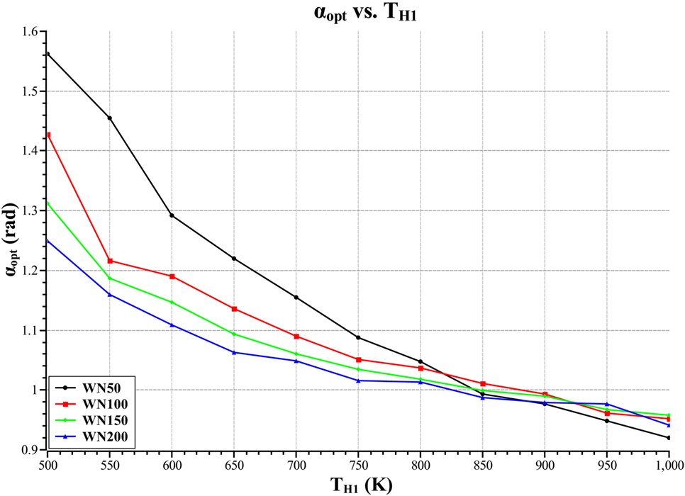
Figure 13 is a plot of optimal phase difference versus heater source temperature.
Figure 13 shows the optimal phase difference versus heater inlet temperature for the four difference mesh types. The plot shows that there is an optimal phase difference for each heater inlet temperature and that the optimal decreases with increasing heater inlet temperature. The plot shows that the optimal differs from the π/2 rads optimal, which is the optimal that is obtained when analyzing the ideal cycle. The reason for this difference is that the phase difference greatly affects the mass flows through the device and the minimum and maximum engine volumes, thus, influencing the engine performance.
Conclusion
This analysis and optimization of a 1,000 cm3 alpha type Stirling engine, with finite heat capacity rates in the heater and cooler and a fixed energy input, represents a new analysis and optimization of Stirling engine geometry, using exergy analysis methodology with an implicit filtering algorithm. This model can be used by Stirling engine designers as an initial optimization procedure to find optimal or near-optimal design points before more complex modeling and experimentation. The analysis shows the significant effect that the choice of regenerator mesh has on engine performance and the size of the optimal regenerator given the specified mesh dimensions. The optimization shows that the WN200 mesh gives the best engine performance of the mesh types analyzed. The analysis has shown that the optimal regenerator length increases and that the optimal engine operating frequency decreases with increasing heater inlet temperature. The optimal volume ratios, optimal heat exchanger geometry, and phase angle are also presented along with a discussion of the trends seen in the optimal variables. In terms of future work, the exergy analysis approach needs to be used with more complex multi-dimensional Stirling engine models. Also, the external heat transfer effects need to be accounted for in the heater and cooler, these effects include the effects of tube thickness and heat transfer coefficient on the outside of the tubes. These effects should be considered as they would affect the heater and cooler working fluid temperatures and, thus, engine performance.
Author Contributions
JW developed the model, carried out the analysis, and wrote the manuscript. TB-O conceived the analysis and revised the manuscript.
Conflict of Interest Statement
The authors declare that the research was conducted in the absence of any commercial or financial relationships that could be construed as a potential conflict of interest.
Acknowledgments
The authors would like to express their gratitude to the University of Cape Town and National Research foundation (NRF) for their financial assistance in completing this work. Opinions expressed and conclusions arrived at are those of the authors and not necessarily attributed to the NRF and UCT.
Funding
This work was funded by the National Research Foundation (NRF) and the University of Cape Town (UCT). Opinions expressed and conclusions drawn are not necessarily attributed to the NRF and UCT.
References
Ahmadi, M. H., Mohammad, A. A., and Mehdi, M. (2016). Investigation of the effect of design parameters on power output and thermal efficiency of a Stirling engine by thermodynamic analysis. Int. J. Low Carbon Technol. 11, 141–156. doi:10.1093/ijlct/ctu030
Babaelahi, M., and Sayyaadi, H. (2015). A new thermal model based on polytropic numerical simulation of Stirling engines. Appl. Energy 141, 143–159. doi:10.1016/j.apenergy.2014.12.033
Bejan, A. (1996). Entropy generation minimization: the new thermodynamics of finite-size devices and finite-time processes. J. Appl. Phys. 79, 1191–1218. doi:10.1063/1.362674
Berchowitz, D., and Urieli, I. (1984). Stirling Cycle Engine Analysis, Alternative Sources of Energy. Bristol: Adam Hilger.
Campos, M. C., Vargas, J. V. C., and Ordonez, J. C. (2012). Thermodynamic optimization of a Stirling engine. Energy 44, 902–910. doi:10.1016/j.energy.2012.04.060
Costea, M., and Feidt, M. (1998). The effect of the overall heat transfer coefficient variation on the optimal distribution of the heat transfer surface conductance or area in a Stirling engine. Energy Convers. Manag. 39, 1753–1761. doi:10.1016/S0196-8904(98)00063-6
de Boer, P. C. T. (2003). Maximum attainable performance of Stirling engines and refrigerators. J. Heat Transfer 5, 911–915. doi:10.1115/1.1597618
Dyson, R. W., Wilson, S. D., and Tew, R. C. (2004). “Review of computational Stirling analysis methods,” in 2nd International Energy Conversion Engineering Conference (Providence: American Institute of Aeronautics and Astronautics), 511–531. doi:10.2514/6.2004-5582
Ellabban, O., Abu-Rub, H., and Blaabjerg, F. (2014). Renewable energy resources: current status, future prospects and their enabling technology. Renew. Sustain. Energy Rev. 39, 748–764. doi:10.1016/j.rser.2014.07.113
Erbay, L. B., and Yavuz, H. (1997). Analysis of the Stirling heat engine at maximum power conditions. Energy 22, 645–650. doi:10.1016/S0360-5442(96)00159-4
Erbay, L. B., and Yavuz, H. (1999). Optimization of the irreversible Stirling heat engine. Int. J. Energy Res 23, 863–873. doi:10.1002/(SICI)1099-114X(199908)23:10<863::AID-ER523>3.0.CO;2-8
Finkelstein, T. (1960). “Generalised thermodynamic analysis of Stirling engines,” in Technical Paper. Detroit: SAE International. doi:10.4271/600222
Gnielinski, V. (1975). “New equations for heat and mass transfer in the turbulent flow in pipes and channels,” in NASA STI/Recon Technical Report A, Berlin, Vol. 75, 8–16.
Joseph, D. D., and Yang, B. H. (2010). Friction factor correlations for laminar, transition and turbulent flow in smooth pipes. Physica D 239, 1318–1328. doi:10.1016/j.physd.2009.09.026
Kongtragool, B., and Wongwises, S. (2003). A review of solar-powered Stirling engines and low temperature differential Stirling engines. Renew. Sustain. Energy Rev. 7, 131–154. doi:10.1016/S1364-0321(02)00053-9
Kongtragool, B., and Wongwises, S. (2006). Thermodynamic analysis of a Stirling engine including dead volumes of hot space, cold space and regenerator. Renew. Energy 31, 345–359. doi:10.1016/j.renene.2005.03.012
Martaj, N., Grosu, L., and Rochelle, P. (2006). Exergetical analysis and design optimisation of the Stirling engine. Int. J. Energy 3, 45–67. doi:10.1504/IJEX.2006.008325
Martaj, N., Grosu, L., and Rochelle, P. (2007). Thermodynamic study of a low temperature difference Stirling engine at steady state operation. Int. J. Thermodyn. 10, 165–176. Available from: http://dergipark.ulakbim.gov.tr/eoguijt/article/view/1034000200
Puech, P., and Tishkova, V. (2011). Thermodynamic analysis of a Stirling engine including regenerator dead volume. Renew. Energy 36, 872–878. doi:10.1016/j.renene.2010.07.013
Senft, J. R. (1998). Theoretical limits on the performance of Stirling engines. Int. J. Energy Res 22, 991–1000. doi:10.1002/(SICI)1099-114X(199809)22:11<991::AID-ER427>3.0.CO;2-U
Senft, J. R. (2002). Optimum Stirling engine geometry. Int. J. Energy Res 26, 1087–1101. doi:10.1002/er.838
Tanaka, M., Yamashita, I., and Chisaka, F. (1990). Flow and heat transfer characteristics of the Stirling engine regenerator in an oscillating flow. JSME Int. J. 33, 283–289.
Thombare, D. G., and Verma, S. K. (2008). Technological development in the Stirling cycle engines. Renew. Sustain. Energ. Rev. 12, 1–38. doi:10.1016/j.rser.2006.07.001
Timoumi, Y., Tlili, I., and Nasrallah, S. B. (2008). Performance optimization of Stirling engines. Renew. Energy 33, 2134–2144. doi:10.1016/j.renene.2007.12.012
Tlili, I., Timoumi, Y., and Nasrallah, S. B. (2008). Analysis and design consideration of mean temperature differential Stirling engine for solar application. Renew. Energy 33, 1911–1921. doi:10.1016/j.renene.2007.09.024
Toghyani, S., Kasaeian, A., and Ahmadi, M. H. (2014). Multi-objective optimization of Stirling engine using non-ideal adiabatic method. Energy Convers. Manag. 80, 54–62. doi:10.1016/j.enconman.2014.01.022
Wills, J. A., and Bello-Ochende, T. (2016). “Theoretical thermodynamic analysis and optimisation of a Stirling engine in terms of dead volume,” in 4th Southern African Solar Energy Conference (SASEC2016) (Stellenbosch).
Keywords: Stirling cycle, exergy analysis, adiabatic, entropy generation, quasi-steady flow, optimization
Citation: Wills JA and Bello-Ochende T (2017) Exergy Analysis and Optimization of an Alpha Type Stirling Engine Using the Implicit Filtering Algorithm. Front. Mech. Eng. 3:21. doi: 10.3389/fmech.2017.00021
Received: 18 September 2017; Accepted: 30 November 2017;
Published: 19 December 2017
Edited by:
Guillermo Rein, Imperial College London, United KingdomReviewed by:
Alexander S. Rattner, Pennsylvania State University, United StatesWei Tang, University of Maryland, College Park, United States
Copyright: © 2017 Wills and Bello-Ochende. This is an open-access article distributed under the terms of the Creative Commons Attribution License (CC BY). The use, distribution or reproduction in other forums is permitted, provided the original author(s) or licensor are credited and that the original publication in this journal is cited, in accordance with accepted academic practice. No use, distribution or reproduction is permitted which does not comply with these terms.
*Correspondence: Tunde Bello-Ochende, dHVuZGUuYmVsbG8tb2NoZW5kZUB1Y3QuYWMuemE=
 James A. Wills
 Tunde Bello-Ochende