 Qitao Zhang
 Jiapeng Yang
- School of Mechanical and Power Engineering, East China University of Science and Technology, Shanghai, China
Rolling bearing is a kind of important part of mechanical equipment, and the noise of the rolling bearing is also one of the important criteria for evaluating the quality of a rolling bearing. In the past, researches on rolling bearings are mainly on bearing vibration when people study the noise of bearings. Few studies have established rolling bearing's noise model. In this paper, a mathematical model for calculating the inner ring's axis center orbit and ball center's trajectory of bearing is established based on the mechanics theory with considering raceway waviness and ball size error. Combined with the acoustics theory, a noise calculation model for deep grove ball bearing is established by taking the bearing inner ring and rolling balls as cylindrical sound source and spherical sound source respectively by using the single source compound method. The influences of waviness wave number, waviness amplitude, bearing speed, bearing load, and ball size errors on bearing noise at a fixed measuring point are studied by numerical calculation. Results show that with the increase of the waviness wave number, the bearing SPL (Sound Pressure Level) will change with irregular way. With the increase of waviness amplitude, bearing speed, bearing load and ball size error band, the bearing SPL will increase.
Introduction
Bearing noise is one of the important indicators for bearing quality. There are many factors that affect the bearing noise. The raceway waviness and the random error of the roller size are major causes of bearing noise.
Wardle deduced an equation of thrust ball bearing's vibration force with considering raceway waviness. Experiments were carried out to verify the accuracy of the vibration force calculation method (Wardle, 1988a,b). Aktürk established a bearing vibration model with considering bearing waviness. This model only considered the bearing vibration, and the bearing noise are not studied (Aktürk, 1999). Wang studied the bearing- rotor dynamics considering raceways waviness, roller waviness and bearing clearance (Liqin et al., 2008). Jang and Jeong proposed a non-linear equation to calculate ball bearing's vibration with considering the bearing waviness, and Runge-Kutta method was used to solve the nonlinear equation. The results were compared with the actual results to prove the accuracy of the model (Jang and Jeong, 2002). Wang and Xu studied the effects of bearing groove shape error and inner ring shape on the bearing noise. Results showed that the bearing noise increases with increase of waviness amplitude (Wang and Xu, 2009). Patel et al. studied the influence of single-point and multi-point errors of deep groove ball bearing raceways on bearing dynamic performance. Numerical calculating results showed that the existence of raceway errors will lead to drastic vibration of the bearing (Patel et al., 2010). Xu and Li studied the effect of the bearing raceway defects on the entire bearing system. It was found by taking the crank connecting rod system as an example that local imperfection will cause stage impact vibration, while the waviness will cause continuous vibration (Xu and Li, 2015). Zhang and Chen established the dynamic model of the bearing system with considering nonlinear factors such as radial clearance and raceway waviness. Results showed that the wave number has an obvious influence on bearing's vibration (Zhang and Chen, 2008). Bouaziz and Fakhfakh studied the effect of the elastic deformation of bearing pads on the acoustic performance of oil lubricated journal bearing. The dynamic characteristics and acoustic characteristics of the bearing are studied by analyzing the pressure fluctuation in journal bearing (Bouaziz et al., 2012). Bai and Wu used sub-source decomposition method to study the radiation noise of angular contact bearing in high-speed electric spindle. Experiments were carried out to verify the accuracy of the method (Bai and Wu, 2017).
The above studies have made some researches on bearing waviness, bearing raceway error, and bearing noise by using different methods. However, most studies only focused on the bearing vibration model with considering raceway waviness. The bearing noise calculation model is not studied, especially when considering raceway waviness and roller size error. The bearing noise models are mostly based on experimental methods. Few noise models established could be directly used to calculate the specific noise of a rolling bearing.
In this paper, the sub-source decomposition method is used to decompose the bearing into several sub-source structures. A noise calculating model for deep groove ball bearing with considering raceway waviness and roller size error is established by using the acoustic theory and sound pressure superposition method based on the noise calculation model of ideal deep groove ball bearing.
Mechanics Analysis of Deep Groove Ball Bearing
Mechanics Analysis Without Considering Ball Size Error
Before the mechanics analysis of the bearing, the following assumptions are introduced: (a) The outer ring is connected to the bearing housing and remains fixed. (b) The inner ring and the shaft are tight fitted. (c) Relative sliding doesn't occur between roller and raceway.
Figure 1 shows the mechanics analysis of deep groove ball bearing without considering ball size error. The inner ring will have a displacement due to the radial force Fr. α is the angle between the direction of the inner ring's maximum deformation and the direction of Fr. β is the azimuth angle of the ball. φ is the angle between two neighboring balls.
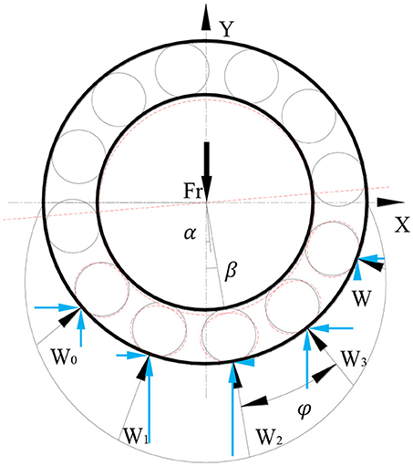
Figure 1. Mechanics analysis of deep groove ball bearing.
According to force balance, the load components of all balls in the vertical direction and the radial force are equal:
In the same way, the components of all balls in the horizontal direction should also be balanced:
Figure 2A shows the roller-raceway contact deformation. The inner ring and the rolling ball will deform under the action of radial force, and the inner ring center moves from O to O′, and the rolling ball center moves from O1 to . According to Ji (2014), the contact between the rolling ball and the raceway is Hertz contact as shown in Figure 2B. When two elastic bodies touch each other, both bodies will have elastic deformation, and the deformation is δ1 and δ2 respectively.
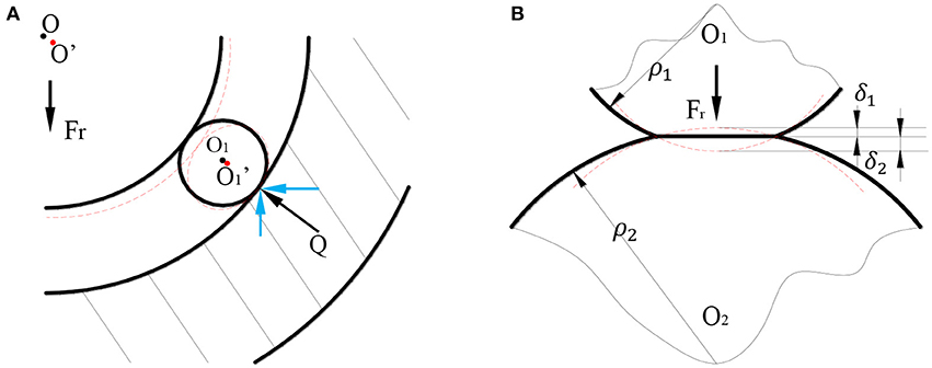
Figure 2. Contact deformation. (A) Roller-raceway contact deformation. (B) Hertz contact deformation.
According to Harris (1984), the calculation formula for the elastic approach δ is:
Where Q is the contact force. E is the elastic modulus of the material. ke is the first type of elliptic integral. μ is the parameter related to the contact curvature, Σρ is the sum of the principal curvatures of the two contact bodies:
According to bearing's material parameters (Junnami, 2001), the calculation formula for the elastic approach can be simplified as:
Where eδ is a parameter of the contact curvature function which can be obtained by looking up the table in Harris (1984). F(ρ) can be calculated as: .
The total elastic approach is equal to the sum of δ1 and δ2:
Mechanics Analysis With Considering Ball Size Error
In the actual working process, the balls of the deep groove ball bearing inevitably have random size errors due to the machining problems. This error is one of the important reasons that causes vibration and produces noise in the bearing. Figure 3 is the mechanics analysis of the deep groove ball bearing with considering ball size error. Before analyzing, the following assumptions are introduced: (a) The error exists only in ball diameter, and ball remains spherical. (b) The balls distribute with equal distances during the operation of the bearing. (c) Only elastic deformation occurs between balls and raceways. Without considering the raceways waviness, assuming that the diameter of the ball is Dw, and the diameter of the off-sized ball is Dwk. Where k is the number of the ball.
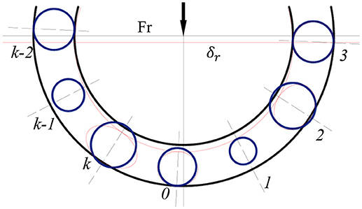
Figure 3. Mechanics analysis with considering ball size error.
In order to accurately analyze the contact deformation between the ball and the raceways, it is necessary to compare the values of the elastic approach δk = δr cos θk and the ball size error Dw − Dwk. When δr cos θk > (Dw − Dwk), which means the elastic approach is larger than the ball size error at this moment, and the rolling balls contact with the raceways at this moment. The actual elastic approach at this time should be δk = δr cos θk − (Dw − Dwk). When δr cos θk < (Dw − Dwk), which means the elastic approach is smaller than the ball size error. At this moment, the balls don't contact with the inner and outer rings, and the actual elastic approach of the ball is δ0 = 0. The actual elastic approach of the rolling element should be δk = δr cos θk − (Dw − Dwk). Where Dwk is the diameter of the kth ball and δk should be positive. θk is the angle between the kth ball and the inner ring center: θk = kϕ − β − α. According to the actual loading condition of the bearing, the relationship between the elastic approach δk of the ball and the radial displacement δr of the inner ring can be obtained:
According to equation (3), the relationship between the radial displacement of the inner ring and the contact force of the ball can be written as:
When the radial force Fr, the bearing type, and relevant material parameters are given, the values of δr and α can be calculated separately by substitute the contact force into the equations (1) and (2). Through the coordinate transformation, the trajectory of the inner ring in the X and Y axis can be obtained respectively, and the elastic approach of the rolling ball can be obtained by equation (7).
Mechanics Analysis With Considering Raceways Waviness
In order to accord with the actual working conditions, this paper also considers the existence of bearing raceways waviness on the base of considering ball size error. During machining, the surface produced will has a certain periodicity of geometrical irregularities and that is waviness. And the main difference between the waviness and surface roughness is the difference in pitch. In general, the pitch of the waviness is >1 mm and <10 mm, while the pitch of the roughness is <1 mm. Since the waviness has a certain periodicity, the Fourier series and the sine curve can be used to represent the surface waviness. In this paper, in order to simplify the calculation, the first-order sine curve is used as the expression formula of waviness. Figure 4A shows the raceways waviness model of the deep groove ball bearing. The solid line represents that there is no waviness on the inner and outer raceways. The dashed line represents that there exists waviness on the raceways of the bearing. The sine function is used to simulate the waviness model in this paper according to the Zhang and Chen (2008) and the waviness definition of the National Standard. Figure 4B shows the first-order of sine curve.
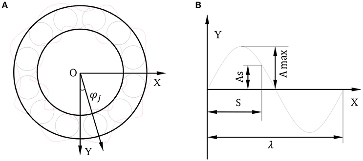
Figure 4. Waviness model. (A) Raceways waviness model. (B) Sine curve.
As shown in Figure 4A, the waviness value of the rolling ball at some moment can be written as:
λ is the average wavelength of the waviness:
βj is the azimuth angle of the ball:
Where A is the waviness value. Aimax is the amplitude of the inner raceway waviness. θ is the initial phase angle. s is the arc length between the contact point and the reference point. Nb is the number of balls. Nw is the wave number. Ri is the inner ring radius of the bearing, ωc is the revolution speed of the ball. ωi is the inner ring angular velocity. Ro is the radius of the outer raceway.
Substituting Equations (10)~(13) into Equation (9), the first-order waviness calculation formula of the inner raceway can be obtained:
Similarly, the first-order waviness calculation formula of the outer raceway can be obtained:
where Aomax is the amplitude of the outer raceway waviness, θo is the initial phase angle.
As shown in Figure 5, the inner and outer raceways waviness and ball size error coexist in deep groove ball bearing. It can be seen that with the effect of the radial force Fr, the inner ring shifts down due to the asymmetrical distribution of the rolling balls. Inner ring squeezes the rolling balls, resulting in contact deformation. According to the analysis of the bearing waviness model, the bearing inner raceway waviness is Pi, and the bearing outer raceway waviness isPo.
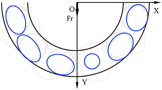
Figure 5. The bearing force chart with considering waviness and ball error.
With considering ball size error and raceways waviness, the elastic deformation of the contact point can be expressed as: δk = [δr cos θk − (Dw − Dwk) + Pk]+.
where θk is the angle between the kth ball and the inner ring's maximum deformation direction: θk = kϕ − β − α. Pk is the variation of the waviness of the inner and outer raceways: Pk = Pi − Po. The subscript “+” indicates that the deformation value is positive.
The actual deformation of the kth ball can be written as:
The contact force of the kth ball can be written as:
when the radial force Fr, the bearing type and relevant material parameters are given, the deformation δr and α can be calculated separately by substitute the contact force into the equations (1) and (2). Through the coordinate transformation, the trajectory of the inner ring in the X and Y axis can be obtained respectively, and the elastic approach of the rolling ball can be obtained by equation (17).
Noise Model for Deep Groove Ball Bearing
Before the establishment of the noise model, the following assumptions should be introduced: (a) The noise concerned is only the part caused by the inner ring and the rolling balls during the movement. (b) The air is an ideal fluid. (c) The air is a static continuous homogeneous medium. (d) The air's density, temperature, pressure, and other parameters are constant.
According to Zhao (1992), the vibration is the source of the noise, and the noise is the characterization of the vibration. In this paper, there are two main sources of bearing noise in the working process. One is the vibration generated by the inner ring, and the other one is the vibration generated by each rolling ball. This paper takes the sound pressure level as the judgment standard of the noise. The volume of the noise generated during the working process is calculated. Figure 6 shows the structure of the deep groove ball bearing. The point A is taken as the measuring point. The distance between the measuring point A and bearing center is 10 mm.
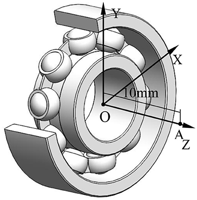
Figure 6. Rolling bearing structure.
Through the reference (Wu, 2011; Du, 2012), according to the wave equation, the bearing geometry can be simplified to a classical sound source model. On this basis, the sound pressure can be calculated, and then the sound pressure level can be obtained according to the sound pressure level equation. After overlaying the sound pressure level, the total sound pressure level will be got.
In this paper, the vibration of the inner ring is considered as a cylindrical sound source model for calculation, and the vibration of the rolling elements is considered as a pulsating sound source model for calculation. Figure 7A shows a cylindrical sound source model and Figure 7B shows a pulsating sound source model.
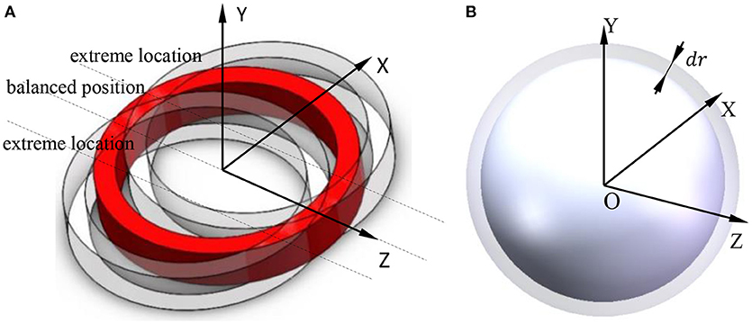
Figure 7. Sound source model. (A) Cylindrical sound source model. (B) Spherical sound source model.
As is shown in Figure 7A, suppose the bearing inner ring vibrates in the X direction at the velocity between two extreme positions at one moment. According to Xia (2015), the sound pressure can be obtained by equation (16):
Where ρ0 is the air density. c0 is the sound velocity in the air, u0 is the maximum amplitude of the vibration, a is the radius of the inner ring, r is the distance between the measuring point A and bearing center.
Similarly, when the inner ring vibrates in Y direction, the same equation can be used to obtain the sound pressure.
When the volume of the rolling ball changes during the rotation, the pulsating ball source model is used to calculate the sound pressure. As shown in Figure 7B, suppose the vibration speed of the rolling ball at a certain moment is u = u(t). According to the acoustic theory, the wave equation can be obtained:
And the general solution of this equation is:
Where A and B are two constants.
According to the acoustics theory, the first term of Equation (21) represents outward radiation, and the second term represents inward radiation. Since this paper consider space radiation, so B = 0, and then:
According to the relationship between the speed and the sound pressure, the sound pressure of the rolling element can be obtained as follows:
where . r0 is the radius of the ball.
The deep-groove ball bearing has several rolling balls, so the sound pressure of rolling balls should be:
Where pi is the sound pressure of each rolling ball.
According to Equations (17) and (18), the total sound pressure pg generated by rolling balls can be obtained:
The total sound pressure of the bearing is:
Where pzi is the sound pressure generated by each sound source.
According to Du (2012), the SPL can be obtained by taking the logarithm of the effective value of the sound pressure to indicate the strength of the sound. The formula of the deep groove ball bearing sound pressure level is:
Where peis the effective value of the sound pressure. pref is the reference sound pressure, (in general pref = 2 × 10⁻⁵Pa). The effect of radiation impedance on sound pressure P is not considered. pe is the effective sound pressure: .
Thus, the sound pressure level of the deep groove ball bearing can be obtained by equation (24).
Figure 8 shows the calculation flow chart of the bearing force and sound pressure level.
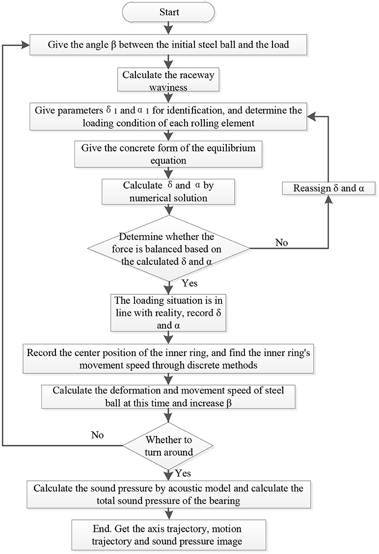
Figure 8. Calculation flow chart.
Example Analysis
The C&U 608 deep groove ball bearing is studied as an example. The specific bearing parameters are shown in Table 1.
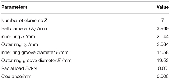
Table 1. Bearing parameters.
Figure 9 shows the axis center orbit of deep groove ball bearing's inner ring when the rotating speed of the bearing is 720 rpm and the radial load is 0.05 kN. It can be seen from Figures 9A,B that the axis center orbit of the inner ring is an irregular curve. Figures 9C,D are the trajectories of the inner ring center in X and Y directions. It can be seen that the inner ring center vibrates within a certain region in X and Y directions. Figures 9E,F are the velocity of the inner ring center in X and Y directions.
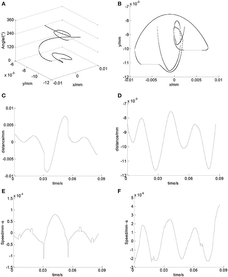
Figure 9. Axis center orbit and velocity of the inner ring center. (A) Axis center orbit of the inner ring. (B) Axis center orbit of the inner ring in XOY plane. (C) Axis center orbit of the inner ring in X direction. (D) Axis center orbit of the inner ring in Y direction. (E) Speed of the inner ring center in X direction. (F) Speed of the inner ring center in Y direction.
Figure 10 shows the trajectory of ball center in X and Y directions. It can be seen that the maximum elastic deformation of rolling balls is about 0.01 mm. Figure 11 shows the velocity of the balls in X and Y directions. It can be seen that in one cycle, the velocity of each ball changes all the time, and all balls' velocity have the same change trend.
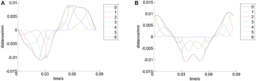
Figure 10. Trajectory of ball center. (A) Trajectory of ball center in X direction. (B) Trajectory of ball center in Y direction.
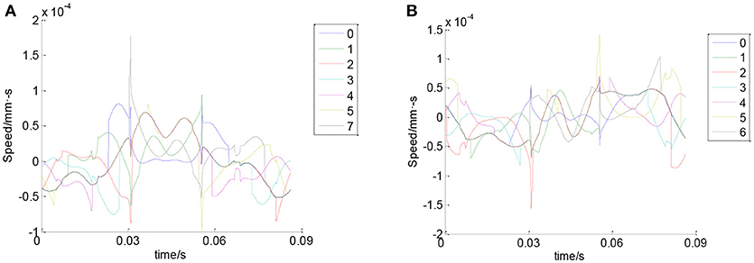
Figure 11. Velocity of the balls. (A) Velocity of the balls in X direction. (B) Velocity of the balls in Y direction.
Figure 12 shows the sound pressure which is generated by the bearing inner ring at point A. It can be seen that the SPL of the inner ring is 20–30 dB for most of the time. Sudden change of the SPL only occurs at several time points. It can be seen from Figure 13 that the SPL of the balls is around 20 dB for most of the time in one cycle. Sudden change of the SPL only occurs at several time points.
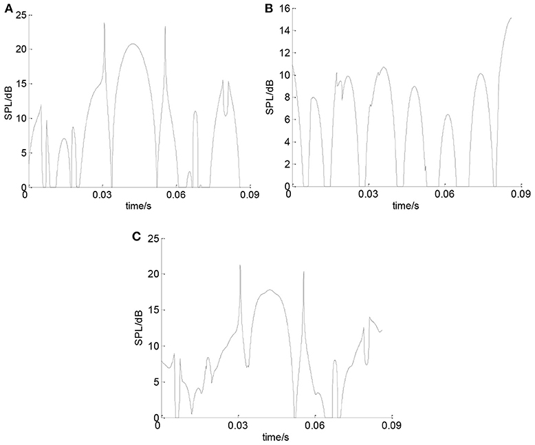
Figure 12. The SPL of the inner ring. (A) SPL of inner ring in X direction. (B) SPL of inner ring in Y direction. (C) Total SPL of the inner ring.
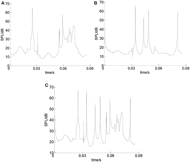
Figure 13. The SPL of the balls. (A) SPL of the balls in X direction. (B) SPL of the balls in Y direction. (C) Total SPL of balls.
Figure 14 is the total SPL of the deep groove ball bearing at point A. It can be seen that the average sound pressure value of the deep groove ball bearing is 29.832 dB. According to the results in Su et al. (2009) and Yan (2009), the same kind of bearing noises obtained by similar conditions and similar measurement modes are 27.8 and 29.4 dB. Because the bearing studied in this paper only considers the influences of the inner and outer ring waviness of the bearing and the size of the roller, and does not consider the influence of the bearing cage vibration and the bearing lubrication performance on the bearing sound pressure level, so the results has a little bit different with the two references. However the magnitude of the sound pressure level are very similar.
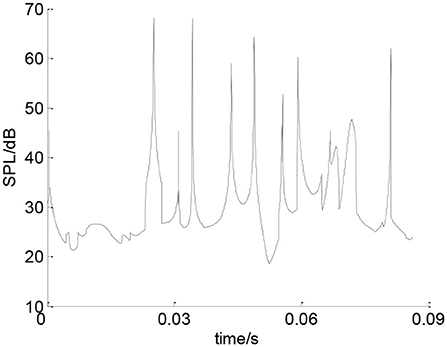
Figure 14. The total SPL of the deep groove ball bearing at point A.
In order to study the effect of wave number on the bearing noise, keeping the other parameters constant, the bearing noise will change with the change of wave number. Figure 14 shows the total SPL of the deep groove ball bearing when the wave number is 7. Figure 15 shows the total SPL of the bearing when the wave number is 5, 6, 8, and 9 respectively. It can be seen that as the wave number increases, the SPL of the bearing noise changes non-linearly with irregular ways. Figure 16A is the curve of the noise sound pressure value with wave number changing from 5 to 9. It can be seen that the changes of the noise cannot be observed obviously. Figure 16B shows the effect of wave number on the average bearing SPL with wave number changing from 5 to 9.
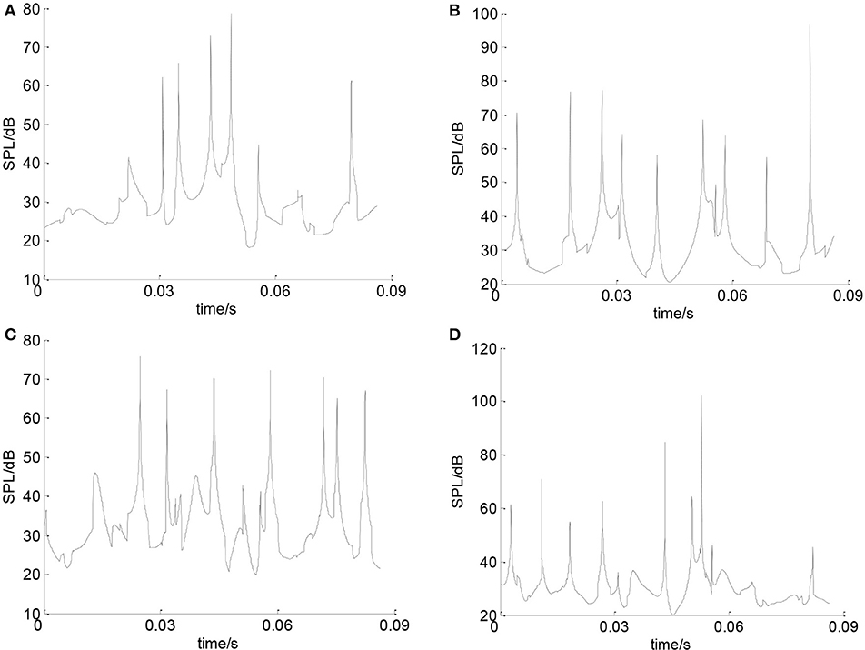
Figure 15. (A) Bearing SPL with 5 waves. (B) Bearing SPL with 6 waves. (C) Bearing SPL with 8 waves. (D) Bearing SPL with 9 waves.
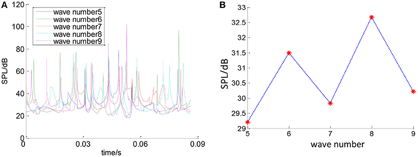
Figure 16. Effect of wave number on bearing noise. (A) Effect of wave number on bearing SPL. (B) Effect of wave number on average bearing SPL.
In order to study the effect of waviness amplitude on the bearing noise, keeping the other parameters constant, the bearing noise will change with the change of waviness amplitude. As shown in Figure 17, with the increase of the initial waviness amplitude, the bearing sound pressure value will also change. It can be seen that as the waviness amplitude increases, the sound pressure generated by the bearing increases.
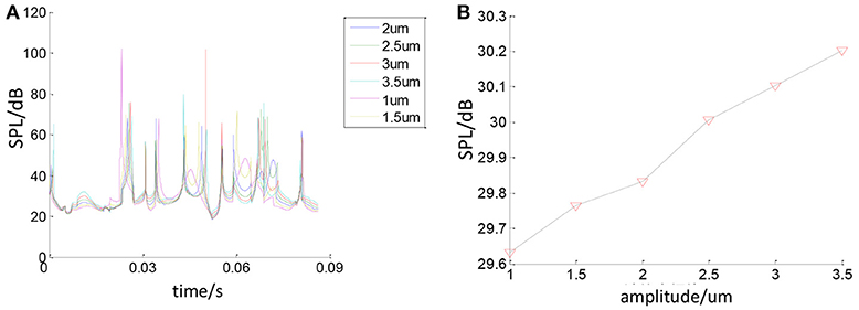
Figure 17. The relationship between the amplitude of the waviness and the sound pressure. (A) Effect of waviness amplitude on SPL. (B) Effect of waviness amplitude on average SPL.
In order to study the influence of the bearing rotating speed on the bearing noise, keeping the other parameters constant, the bearing noise will change with the change of rotating speed. Figure 18A is the total change about the bearing sound pressure value within one cycle. Figure 18B shows the change of the average sound pressure value. It can be seen that the bearing sound pressure value will change with the change of rotating speed. As the bearing rotating speed increases, the sound pressure generated by the bearing increases.
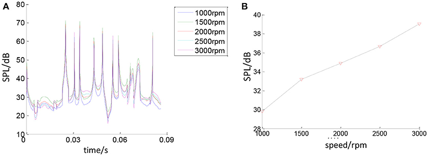
Figure 18. The relationship between bearing rotating speed and bearing SPL. (A) Effect of speed on bearing SPL. (B) Effect of speed on average bearing SPL.
Figure 19 shows the relationship between the bearing load and bearing SPL. As shown in Figure 19A, the SPL of the bearing noise will change with the bearing load. Figure 19B shows the average bearing SPL with different bearing loads. It can be seen that as the bearing load increases, the average bearing SPL increases.
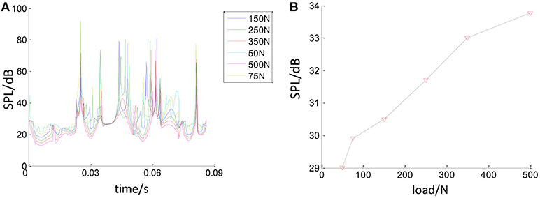
Figure 19. The relationship between bearing load and bearing SPL. (A) Effect of load on bearing SPL. (B) Effect of Load on average bearing SPL.
The SPL of bearing noise will change with the change of ball size errors. This paper uses random function of MATLAB to generate ball errors. Figure 20 shows the relationship between ball errors and bearing SPL. Figure 20A shows the errors of all balls. Figures 20B–F show the changes of bearing SPL when the ball size error band is 1, 1.5, 2, 2.5, and 3 μm. When these images are merged together as shown in Figures 20G,H, it can be seen that as the ball size error band increases, the bearing SPL also increases.
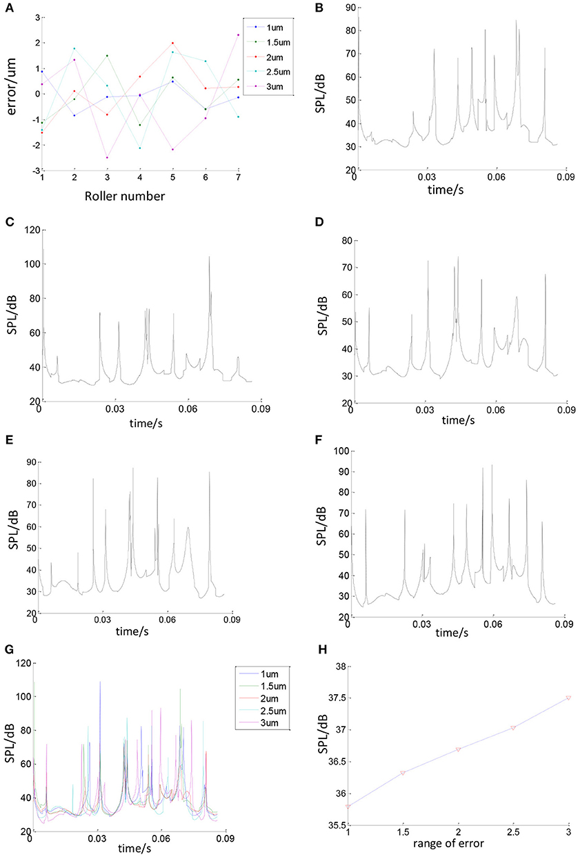
Figure 20. The relationship between ball errors and bearing SPL. (A) Ball errors distribution. (B) Roller error range is 1 um. (C) Ball size error band is 1.5 um. (D) Ball size error band is 2 um. (E) Ball size error band is 2.5 um. (F) Ball size error band is 3 um. (G) Effect of ball errors on bearing SPL. (H) Effect of ball errors on average bearing SPL.
Conclusions
(1) Based on the force analysis of the deep groove ball bearing with considering the ball size errors and the raceways waviness, a mechanical model for calculating inner ring's axis center orbit and ball center's trajectory is established. Based on this model, through the basic acoustic model, the inner ring of the bearing is considered as the cylindrical sound source, and the rolling ball is considered as the spherical sound source, a noise calculating model for the inner ring and rolling elements of deep groove ball bearing is established.
(2) Take the C&U 608 bearing as an calculating example. The effects of waviness amplitude and waviness wave number on the bearings SPL at one fixed measuring point are studied by using MATLAB. Results show that with the increase of the bearing waviness amplitude, the bearing SPL at the measuring point will also increase, and the increasing trend is roughly linear. With the increase of the waviness wave number, the bearing SPL at the measurement point will change, and the change trend is within the study scope. There is no necessary relationship between the wave number and bearing SPL. With the increase of bearing speed, bearing load and ball size error band, the bearing SPL at the measuring point will also increase.
Author Contributions
QZ: conception or design of the work, data calculation, data analysis and interpretation, drafting the article; JY: critical revision of the article; QA: final approval of the version to be published.
Conflict of Interest Statement
The authors declare that the research was conducted in the absence of any commercial or financial relationships that could be construed as a potential conflict of interest.
Acknowledgments
The authors would like to thank the project Modern mechanical theory research and related products research and development (DA17014) supported by Shanghai Summit Discipline in Design and the National Natural Science Foundation of China (Grant number 51505148). The authors are sincerely grateful to honorable reviewers for their valuable review comments, which substantially improved the article.
References
Aktürk, N. (1999). The effect of waviness on vibrations associated with ball bearings. Tribol. Trans. ASME. 121, 667–677.
Bai, X. T., and Wu, Y. H. (2017). Radiation noise of the bearing applied to the ceramic motorized spindle based on the sub-source decomposition method. J. Sound Vibrat. 410, 35–48. doi: 10.1016/j.jsv.2017.08.029
Bouaziz, S., Fakhfakh, T., and Haddar, M. (2012). Acoustic analysis of hydrodynamic and elasto-hydrodynamic oil lubricated journal bearings. J. Hydrodyn. Ser. B 24, 250–256. doi: 10.1016/S1001-6058(11)60241-2
Jang, G. H., and Jeong, S. W. (2002). Nonlinear excitation model of ball bearing waviness in a rigid rotor supported by two or more ball bearings considering five degrees of freedom. J. Tribol. 124, 82–90. doi: 10.1115/1.1398289
Ji, P. (2014). The influence of the error of the rolling element of the deep groove ball bearing on the stress change law. J. East China Univers. Sci. Technol. 40, 667–674. doi: 10.3969/j.issn.1006-3080.2014.05.022
Liqin, W., Li, C., Dezhi, Z., and Le, G. (2008). Nonlinear dynamics behaviors of a rotor roller bearing system with radial clearances and waviness considered. Chin. J. Aeronaut. 21, 86–96. doi: 10.1016/S1000-9361(08)60012-6
Patel, V. N, Tandon, N., and Pandey, R. K. (2010). A Dynamic model for vibration studies of deep groove ball bearings considering single and multiple defects in races. J. Tribol. 132:041101. doi: 10.1115/1.4002333
Su, Z. A., Chen, J. S., and Wang, C. K. (2009). Application of vibration method in bearing noise measurement. J. Harbin Bear. 30, 59–62. doi: 10.3969/j.issn.1672-4852.2009.02.030
Wang, Z., and Xu, L. (2009). Influence of channel shape error on vibration and noise of deep groove ball bearings. J. Harbin Bear. 30, 23–24. doi: 10.3969/j.issn.1672-4852.2009.04.011
Wardle, F. P. (1988a). Vibration Forces Produced by Waviness of the Rolling Surfaces of Thrust Loaded Ball Bearing, Part 1: Theory. Proc. IMechE. 202, 305–312.
Wardle, F. P. (1988b). Vibration Forces Produced by Waviness of the Rolling Surfaces of Thrust Loaded Ball Bearing, Part 2: Experimental Validation. Proc. IMechE 202, 313–319.
Xia, X. T. (2015). Research on Vibration and Noise of Rolling Bearing. Beijing: National Defense Industry Press.
Xu, L. X., and Li, Y. G. (2015). Modeling of a deep-groove ball bearing with waviness defects in planar multi-body system. Multi-body Syst. Dyn 33, 229–258. doi: 10.1007/s11044-014-9413-z
Yan, G. B. (2009). Study on Vibration & Noise Reduction Technology of Ball Bearing. Harbin Institute of Technology, Harbin Institute of Technology master's thesis, Harbin.
Zhang, Y. Q., and Chen, J. J. (2008). Nonlinear dynamic characteristics of rolling bearing-rotor system considering surface waviness. J. Aerospace Power. 23, 1731–1736. doi: 10.13224/j.cnki.jasp.2008.09.019
Zhao, C. L. (1992). Deep Groove Ball Bearing Vibration Mechanism and Control [D]. Luoyang Institute of Technology, Luoyang Institute of Technology master's thesis, Luoyang.
Appendix
Notation
A, waviness amplitude(um)
Aimax, maximum amplitude of the inner ring waviness (um)
Aomax, maximum amplitude of the outer ring waviness (um)
α , The angle between the inner ring offset and the radial force (°)
β , The angle between the force and the rolling element (°)
c0, air sound velocity (m/s)
Dw, Standard roller diameter (mm)
Dw0, kth roller diameter(mm),
E, Elastic modulus (Pa)
ΣρMain curvature
eδ, Contact curvature
Fr, Radial load (kN)
k, The number of the ball
ke, The first type of elliptic integral
Nb, bearing rolling element quantity
Nw, wave number
Pi, amplitude of the inner ring waviness (um)
Po, amplitude of the outer ring waviness (um)
Pk, variation of the waviness of the inner and outer rings (um)
pzi, sound pressure generated by each sound source (Pa)
pi, sound pressure level of each rolling element (Pa)
pe, effective value of the sound pressure (Pa)
pref, reference sound pressure (Pa)
pz, the total sound pressure (Pa)
pg, roller's total sound pressure (Pa)
p, single roller's sound pressure(Pa)
ρ0, air density
Q, Contact load (kN)
ri, inner ring radius(mm)
ro, outer ring radius(mm)
u0, amplitude of the vibration (m)
Wk, kth Contact force (kN)
ωc rolling element revolution velocity (rad/s)
ωi, inner ring angular velocity (rad/s)
ωo, outer ring angular velocity (rad/s)
φ , The angle between the two rolling elements (°)
δ normal elastic deformation of roller-raceway contact (mm)
δr, inner ring radial displacement (mm)
δk, roller radial displacement(mm)
μ , Parameter related to the contact curvature
θk, the angle between the k ball and the inner ring center offset direction
Keywords: deep groove ball bearing, waviness model, noise model, roller size error, numerical calculation
Citation: Zhang Q, Yang J and An Q (2018) Noise Calculation Method for Deep Groove Ball Bearing With Considering Raceway Surface Waviness and Roller Size Error. Front. Mech. Eng. 4:13. doi: 10.3389/fmech.2018.00013
Received: 30 June 2018; Accepted: 11 September 2018;
Published: 03 October 2018.
Edited by:
Giuseppe Carbone, Politecnico di Bari, ItalyReviewed by:
Yoshitaka Nakanishi, Kumamoto University, JapanCarmine Putignano, Politecnico di Bari, Italy
Copyright © 2018 Zhang, Yang and An. This is an open-access article distributed under the terms of the Creative Commons Attribution License (CC BY). The use, distribution or reproduction in other forums is permitted, provided the original author(s) and the copyright owner(s) are credited and that the original publication in this journal is cited, in accordance with accepted academic practice. No use, distribution or reproduction is permitted which does not comply with these terms.
*Correspondence: Qitao Zhang, enF0MTAxMDEwYUAxNjMuY29t
Qi An, YW5xaUBlY3VzdC5lZHUuY24=