 Tetsuya Akiyama
 Yuki Yoshioka
 Takuro Honda
 Yuta Nakashima
 Yoshitaka Nakanishi
- 1Graduate School of Science and Technology, Kumamoto University, Kumamoto, Japan
- 2Faculty of Science and Engineering, Kumamoto University, Kumamoto, Japan
When performing a cutting operation, a water-soluble cutting fluid may be used for cooling. Labyrinth and oil seals are commonly used in the rotating centers of machine tools to prevent the cutting fluid and dust from entering the inner parts. However, these seals do not demonstrate adequate functionality in a water-based environment. Therefore, a new rotary shaft seal was devised to separate the water-soluble cutting fluid from interacting with air. The rotary shaft seal was made from polyvinyl formal (PVF). Because PVF is a hydrophilic material, it is expected to provide suitable functionality as a seal in a water-based environment. Performance evaluations of PVF and oil seals were experimentally obtained and compared from the point of view of frictional torque, water-soluble cutting fluid leakage volume, and service life as a seal.
Introduction
Rotary shaft seals used to separate liquid and air are important mechanical components in machine tools. Advances in rotary shaft seals have improved the quality of many machine products. Oil seals and labyrinth seals are well-known as general rotary shaft seals (Bock et al., 2003; Kim and Cha, 2009; Flitney, 2014). An oil seal forms a sliding surface between the rubber seal lip and the rotating shaft and is a component that prevents liquid leakage. Labyrinth seals, on the other hand, have a complicated fluid passage and rotate with the shaft, preventing leakage. Labyrinth seals are also mainly made of metals and are used in oil-based environments to prevent dust from entering the bearing housing or similar critical areas of machines. In addition, while the oil seal is a contact seal, one of the salient features of a labyrinth seal is that it is a non-contact seal. In general, the rotary shaft seal demonstrates excellent functionality in preventing the leakage of liquid when the speed of the rotating shaft is high or in oil-based environments. However, there are very few types of rotary shaft seals that can be used in a water-based environment. As a consequence of rapid technical innovation, there are increasingly more conditions under which shaft seals are required to operate these days. For example, when performing a cutting operation with a machine tool, water may be used for cooling the workpiece or turning tool (El Baradie, 1996a,b; Debnath et al., 2014). In a rotation center attached to a lathe or similar machine, an oil or a labyrinth seal is incorporated to prevent the liquid from entering the rotation center (Malleswara Rao et al., 2011). However, these seals do not demonstrate excellent functionality in a water-based environment. A rotary shaft seal is needed to protect the mechanical elements from water-based liquid ingress in such a situation. In addition, the energy loss caused by the shaft seal should be minimized. Therefore, a rotary shaft seal that is suitable for such an environment is required in place of conventional seals. Accordingly, a new type of rotary shaft seal was specially designed to prevent water-based liquid leakage at a low frictional torque. A contact-type rotary shaft seal made of the hydrophilic material polyvinyl formal (PVF) was devised because such a seal using a hydrophilic material could show good performance just as an oil seal using a hydrophobic material shows an excellent function (Nakanishi et al., 2009). In a previous study, a shaft seal used an aqueous solution of polyethylene glycol (PEG), which is a non-Newtonian fluid; this solution was injected between the PVF seal rings to support the lubrication and sealing action at the sliding surface (Honda et al., 2018a). In another study, a new PVF seal with a simplified configuration that did not use a PEG solution was proposed (Honda et al., 2018b). While an oil seal demonstrates fluid lubrication on the sliding surface, a rotary shaft seal made of PVF is designed to provide boundary lubrication because oil films do not form easily in water-based environments (Bhate et al., 2004; Nakanishi et al., 2016, 2018; Honda et al., 2018a).
In this paper, we describe the development of a new rotary shaft seal for separating water and air using PVF as the sealant material under conditions where the rotary shaft operates at high speeds. This rotary shaft seal was experimentally evaluated from the perspective of frictional torque, water-soluble cutting fluid leakage volume, and service life.
Materials and Methods
Sealing System
Figure 1 shows a schematic of the rotation center. The rotation center is mainly used to support the free end of the test piece in a machine tool, such as a lathe. Oil and labyrinth seals are generally used over the rotation centers in the sealing parts to prevent cutting fluids from entering bearing housings or similar areas. These seals prevent oil leaks and dust from entering these critical areas, and their functionality is fully demonstrated in an oil-based environment. However, when the oil-based environment is replaced with a water-based environment, these seals do not perform adequately. This is because oil seals are generally used to prevent leakage of oil and their seal lips are made of elastomer, which has hydrophobic characteristics. Therefore, oil seals sometimes suffer from inadequate lubrication of seal lips in water-based environments. Labyrinth seals have complex flow passages and they prevent leakage flow by operating at high shaft speed when fluids or gases enter into the flow passages. According to the seal structure, some leakage should be allowed when the shaft speed is low or shows zero. Furthermore, it is shown that the leakage amount of water is larger than that of oil because water has lower viscosity (Strmčnik and Majdič, 2017). Thus, PVF (PVA sponge D (D), SEIWA INDUSTRY Corp., Ltd., Japan), which is a hydrophilic material, was proposed as a sealing material because it is thought that a seal performs better if the seal lip is made of hydrophilic or hydrated material when water is used as a subject fluid.
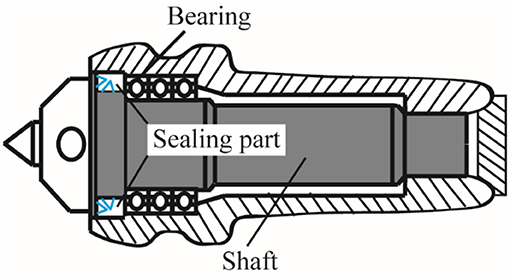
Figure 1. Schematic of the rotation center.
Figure 2 shows a schematic of the sealing system. A nitrile rubber oil seal (AC0678E0, NOK Corp., Japan) was also tested as a comparison to evaluate the PVF seal. The oil seal forms dynamic seal face between the seal lip and the shaft as shown in Figure 2A. Similarly, the PVF seal forms dynamic seal face between the inner surface of the seal and the shaft (Figure 2B). These two types of seals are assembled as shown in Figure 2C, and are designed to prevent leakage of the cutting fluid. The inner diameter of the PVF seal was 15.5 mm for a rotating shaft diameter of 16 mm (Figure 3). This mechanism prevents the cutting fluid leakage from between the inner surface of the PVF seal and the rotating shaft owing to the tightening action of the PVF seal on the rotating shaft. The dimensions of seal lips were decided considering practical applications such as easy replacement of a conventional seal with a new one. The thickness was fixed at 5 mm. It was adjusted by milling under dry conditions so that the swelled seal lip made proper contact against the shaft. The PVF seal was attached to the shaft under wet conditions. Furthermore, as listed in Table 1, the very porous structure of PVF may lead to the seepage of the cutting fluid through the PVF pores. Therefore, a silicone sealing material (PRO2020MJ, Kanpe Hapio Co., Ltd., Japan) was pasted on the side surfaces to prevent leakage, except from the dynamic seal face. Furthermore, as the PVF seal has a water retention property, the seal itself was expected to play the role of lubricant. The rotating shaft used for the test was made of stainless steel (SUS304, JIS). Figure 4 shows the surface profile of the rotating shaft before the test (SE300-30, Kosaka Laboratory Ltd., Japan). In the test, a water-soluble cutting fluid prepared by diluting 200 mL of cutting oil (UNISOLUBLE-SG (N), JXTG Nippon Oil & Energy Corp., Japan) with 6,000 mL of tap water was used. The water-soluble cutting fluid has the primary advantage of excellent cooling capability.
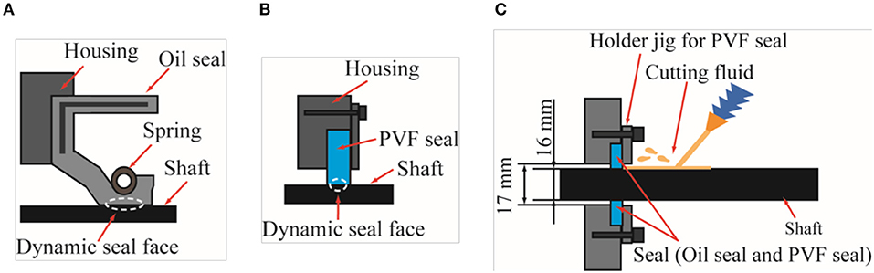
Figure 2. (A) Schematic of dynamic seal face between an oil seal and the shaft. (B) Schematic of dynamic seal face between a PVF seal and the shaft. (C) Schematic of sealing system.
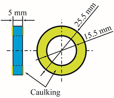
Figure 3. Shape of the PVF seal.
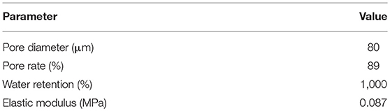
Table 1. Parameters of the PVF seal.
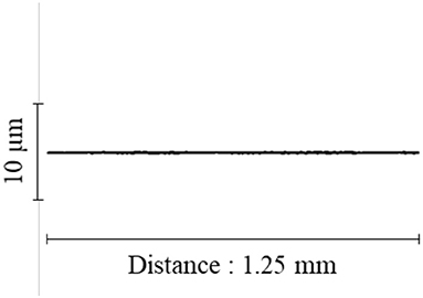
Figure 4. Surface profile of the rotating shaft before testing.
Testing Device and Evaluated Methods
Figure 5 shows the test apparatus. The rotating shaft was continuously rotated at a constant speed of 5,000 rpm by AC servomotor (NXM620A, Oriental motor Corp., Ltd., Japan). In addition, the power consumed by this servomotor was measured using a voltage logger (LR5042, HIOKI E.E. Corp., Japan), and this was converted as a frictional torque generated by the rotary shaft seal. In this test, the total operating time was set for 5,000 h with a temporary suspension period of 720 h (30 days) occurring 2,500 h after the start. This was because, assuming that the seal is incorporated in the part of a factory machine tool for example, a situation in which the machine in the factory is stopped for 1 month is conceivable. The color of the cutting fluid changed when it was used for around 10 days. Therefore, the cutting fluid was replaced every 250 h. The limit value of the leakage volume of cutting fluid during the test was set to 0.1 mL/h. When this value was exceeded, it was considered that the rotary shaft seal had lost its leakage prevention functionality, and the test was terminated.
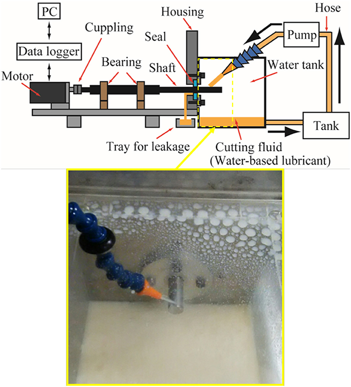
Figure 5. Schematic and photograph of the testing device.
Results and Discussion
Frictional Torque and Amount of Leakage
Figure 6 shows the frictional torque. In the graph of the oil seal, there are points where a negative value is given. This is probably because the long test caused a drift in the reference point of 0 N· mm. In addition, the fluctuation of the torque value was large, with larger torque values shown for the initial torque and at other times. Furthermore, after the end of the stoppage period of 720 h (30 days), the oil seal leaked cutting fluid from immediately after the test was resumed and the leakage volume exceeded 0.1 mL/h; thus, the total operating time was 2,500 h. The average value of the frictional torque was 5.09 N· mm.
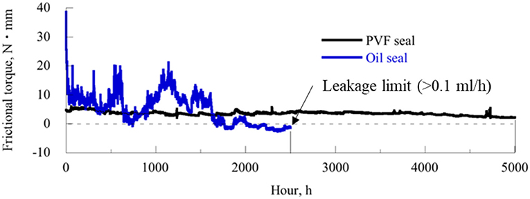
Figure 6. Frictional torque.
The PVF seal demonstrated low torque and a stable value. Furthermore, although the oil seal leaked cutting fluid immediately after the test was resumed after the end of the stoppage period, the PVF seal experienced no such leakage of cutting fluid and the test was continued up to 5,000 h. The average value of the frictional torque was 3.61 N· mm.
The larger the frictional torque, the larger the energy loss caused by shaft seal. The PVF seal showed lower frictional torque than the oil seal, which meant that the PVF seal reduced the energy loss of the mechanical system. Consequently, the PVF seal had a longer service life. The PVF seal was superior because it beneficially reduced the frictional loss as much as possible. Cutting fluid leakage volumes in both tests were below the measurement limit, excluding the end of the oil seal test.
Dynamic Seal Face
Figure 7 shows the microscopy (400-CAM052, SANWA SUPPLY INC., Japan) and SEM (TM3030, Hitachi High-Technologies Co. Ltd., Japan) images on the dynamic seal faces of the two seals. The tip of the pre-test lip of the oil seal was observed to be worn and degraded after the test. This may be one cause of leakage. The oil seal should prevent liquid leakage owing to a fluid lubrication mechanism that forms a thin oil film on the dynamic seal face under an oil environment, thereby realizing low friction and wear. However, as a water-soluble cutting fluid was used in this experiment, a sufficient oil film was not formed in the dynamic seal face section, whereupon the seal lip and the rotating shaft were in direct contact with each other. This may be why the value of the torque was also high, and wear of the seal lip section was observed. The PVF seal was designed to operate by boundary lubrication. Namely, the PVF seal prevents leakage of water by being attached firmly to the rotating shaft to decrease clearance between the seal lip and the shaft regardless of its rotating condition. Moreover, PVF adsorbs water on the molecular level, so lubrication of the inner surface of the PVF seal is guaranteed even if the seal lip is tightly attached to the rotating shaft. The PVF seal showed less friction and smaller amounts of wear and leakage during the test.
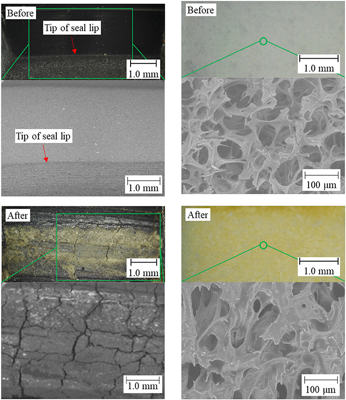
Figure 7. Microscopy and SEM images of the dynamic seal face. Figures to the left are of the oil seal, and figures to the right are of the PVF seal.
After microscope observations after both tests, it was observed that the dynamic seal faces section is discolored. This was the color of the cutting fluid itself, and it can be concluded that this is due to the effect of the cutting fluid. Therefore, this discoloration is considered to not affect the functionality of the seal itself.
Roughness of the Rotating Shaft
Figure 8 shows the state of the shafts after the test and the surface profiles. From these figures, it was also confirmed that the shaft on which the oil seal was used had a rough surface and that a deep scratch was caused by the seal lip. This indicates that the rotating shaft and the seal lip are in direct contact with each other, and there probably was insufficient lubrication between them. On the contrary, in comparison with the rotating shaft on which the oil seal was used, deep scratches were not observed on the rotating shaft on which the PVF seal was used and the surface was also relatively smooth. From this, it can be said that the PVF seal has low friction and functions sufficiently as a seal under a water environment.
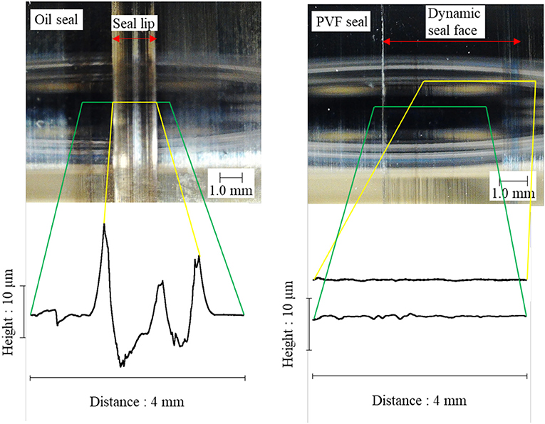
Figure 8. Microscopy images and surface profiles of both rotating shafts.
Conclusion
A new PVF seal was developed as a rotary shaft seal for preventing leakage of water-soluble cutting fluid. The performance of the PVF seal and an oil seal were experimentally evaluated and compared. Under the condition that the rotational speed of the rotating shaft is 5,000 rpm under a water environment, the PVF seal is superior to the oil seal in terms of frictional torque, leakage volume, and service life.
Author Contributions
TA designed this research work and wrote the manuscript. YY and TH conducted the experiments. Both YuN and YoN managed and supervised all aspects of this work.
Conflict of Interest Statement
The authors declare that the research was conducted in the absence of any commercial or financial relationships that could be construed as a potential conflict of interest.
References
Bhate, N., Thermos, A. C., Aksit, M. F., Demiroglu, M., and Kizil, H. (2004). “Nom-metallic brush seals for gas turbine bearings,” in Proceedings of ASME Turbo Expo: Power for Land, Sea, and Air. Vienna.
Bock, E., Vogt, R., and Schreiner, P. (2003). New radial shaft seal concept for sealing hydraulic pumps and motors. Seal. Technol. 11, 6–10. doi: 10.1016/S1350-4789(03)11016-1
Debnath, S., Reddy, M. M., and Yi, Q. S. (2014). Environmental friendly cutting fluids and cooling techniques in machining: a review. J. Cleaner Prod. 83, 33–47. doi: 10.1016/j.jclepro.2014.07.071
El Baradie, M. A. (1996a). Cutting fluids: part I. Characterisation. J. Mater. Process. Technol. 56, 786–797.
El Baradie, M. A. (1996b). Cutting fluids: part II. Recycling and clean machining. J. Mater. Process. Technol. 56, 798–806.
Flitney, R. K. (2014). A description of the types of high speed rotary shaft seals in gas turbine engines and the implications for cabin air quality. J. Biol. Phys. Chem. 14, 85–89. doi: 10.4024/17FL14R.jbpc.14.04
Honda, T., Kasamura, K., Nakashima, Y., Higaki, H., and Nakanishi, Y. (2018a). Low-friction shaft seal composed of bio-inspired materials covering low-speed range under water environment. Proc. Inst. Mech. Eng. J J. Eng. Tribol. 232, 36–42. doi: 10.1177/1350650117738702
Honda, T., Nakashima, Y., Higaki, H., and Nakanishi, Y. (2018b). Fiber reinforcement of hydrophilic materials for a low-torque shaft seal in water environment. Mech. Eng. Lett. 4, 1–8. doi: 10.1299/mel.17-00590
Kim, T. S., and Cha, K. S. (2009). Comparative analysis of the influence of labyrinth seal configuration on leakage behavior. J. Mech. Sci. Technol. 23, 2830–2838. doi: 10.1007/s12206-009-0733-5
Malleswara Rao, J. N., Chenna Kesava Reddy, A., and Rama Rao, P. V. (2011). Evaluation of optimum values of surface roughness on aluminum work piece using roller burnishing. Int. J. Eng. Res. Technol. 4, 293–303.
Nakanishi, Y., Honda, T., Kasamura, K., Nakashima, Y., and Higaki, H. (2018). Bio-inspired seal lip for application in electric vehicle coolant pumps. Mech. Eng. Lett. 4, 1–7. doi: 10.1299/mel.17-00654
Nakanishi, Y., Honda, T., Nakashima, Y., and Higaki, H. (2016). Shaft seal for separation of water and air with low frictional torque. Tribol. Int. 94, 437–445. doi: 10.1016/j.triboint.2015.10.007
Nakanishi, Y., Takashima, T., Higaki, H., Shimamoto, K., Ueno, T., Miura, H., et al. (2009). Development of biomimetic bearing with hydrated materials. J. Biomech. Sci. Eng. 4, 249–264. doi: 10.1299/jbse.4.249
Keywords: live center, waterproof, seal lip, hydrated material, polyvinyl formal
Citation: Akiyama T, Yoshioka Y, Honda T, Nakashima Y and Nakanishi Y (2018) Hydrated Seal Lip for Live Center in Machine Tools. Front. Mech. Eng. 4:14. doi: 10.3389/fmech.2018.00014
Received: 20 July 2018; Accepted: 12 September 2018;
Published: 02 October 2018.
Edited by:
Martin Hartl, Brno University of Technology, CzechiaCopyright © 2018 Akiyama, Yoshioka, Honda, Nakashima and Nakanishi. This is an open-access article distributed under the terms of the Creative Commons Attribution License (CC BY). The use, distribution or reproduction in other forums is permitted, provided the original author(s) and the copyright owner(s) are credited and that the original publication in this journal is cited, in accordance with accepted academic practice. No use, distribution or reproduction is permitted which does not comply with these terms.
*Correspondence: Yoshitaka Nakanishi, eS1uYWthQG1lY2gua3VtYW1vdG8tdS5hYy5qcA==