 Md Mamun Molla
 Md Jahidul Haque
 Md Amirul Islam Khan
- 1Department of Mathematics and Physics, North South University, Dhaka, Bangladesh
- 2Department of Electrical and Computer Engineering, North South University, Dhaka, Bangladesh
- 3School of Civil Engineering, University of Leeds, Leeds, United Kingdom
- 4Department of Mechanical Engineering, University of Technology Sydney, Sydney, NSW, Australia
A two-dimensional (2D) multiple-relaxation-time (MRT)-lattice Boltzmann method (LBM) is used for porous media with the Brinkman–Forchheimer extended Darcy model to investigate the natural and mixed convection flows in a square cavity. This Brinkman–Forchheimer model is directly applied by using the forcing moments as a source term. A Tesla K40 NVIDIA graphics card has been used for the present graphics processing unit (GPU) parallel computing via compute unified device architecture (CUDA) C platform. The numerical results are presented in terms of velocity, temperature, streamlines, isotherms, and local and average Nusselt numbers. For the wide range of Rayleigh numbers, (Ra = 103 to 1010), Reynolds numbers, Darcy numbers, and porosities, the average Nusselt number is compared with the available results computed by finite element method (FEM) and single-relaxation-time (SRT) lattice Boltzmann method-LBM and, showing great compliance. The results are also validated with the previous experimental results. The simulations speed up to a maximum of 144x using CUDA C in GPU compared with the time of FORTRAN 90 code using a single core CPU simulation.
1. Introduction
In recent years, graphics processing units (GPUs) have played a large role in using high-performance computing (HPC) because of the GPU's significantly higher performance compared to traditional central processing unit (CPU) based processors. A GPU has many slim processing units on a single chip and performs in parallel a very large number of operations on a correspondingly large number of operands. Graphics processing unit computing is a heterogeneous simulation system, a small part is run sequentially by the CPU, and the larger part is run in GPU. It has already been established that the GPU parallel computing is well-regarded because of the remarkable floating point arithmetic performance. Currently the GPU is considered a computational accelerator that processes a massively multi-threaded architecture, which has been widely used for graphical and general purpose computations, such as molecular dynamics simulations and computational fluid dynamics (Ye et al., 2015; Calore et al., 2016).
Fluid flow and convective heat transfer through porous media is an interesting and useful research area because of its application in the fields of science and engineering, such as hydrology, civil and mechanical engineering, chemical engineering and petroleum engineering, thermal management of electronic cooling, and the improvement of heat transfer systems Guo and Zhao (2005). Guo and Zhao (2002) first proposed Bhatnagar-Gross-Krook (BGK) or single-relaxation-time (SRT)-lattice Boltzmann method (LBM) for isothermal incompressible flow in porous media. In their model, the porosity parameter introduced through equilibrium distribution function added the forcing term into the evolution equation to account for the linear and non-linear drag forces of media using Darcy's term and Forchheimer's term. They successfully applied their model for two-dimensional (2D) Poiseuille flow, Couette flow, and lid-driven cavity flow and compared their LBM results with the analytical and finite difference solutions. Later on, Guo and Zhao (2005) extended their study of convective heat transfer using the same SRT-LBM and successfully simulated the temperature field for the natural convection of side-heated cavity and mixed convection of the channel flow through porous media.
Following Guo and Zhao (2002) and Seta et al. (2006a,b) we studied the Poiseuille flow and natural convection flow in a side-heated cavity filled with porous media using the SRT-LBM for the non-Darcy regime, considering 103 ≤ Ra ≤ 106. For higher Rayleigh numbers (Ra), 103 ≤ Ra ≤ 1010, an extensive investigation has been done by Vishnampet et al. (2011) considering the Darcy and non-Darcy regime using SRT-LBM and compared their results with the available numerical and experimental results. The above-mentioned SRT-LBM has many advantages from a computational viewpoint: There is intrinsic parallelism of the algorithm and the simplicity of programming over traditional finite difference, finite volume, and finite element methods (FEMs). It has been successfully used in various complex fluid systems, such as multiphase flow (Shan and Chen, 1994), suspension in fluids (Ladd, 1997), magneto-hydrodynamics flow (Premnath and Pattison, 2005; Nemati et al., 2012), nanofluids (Fattahi et al., 2012), and flow through porous media with variable porosity (Guo and Zhao, 2005; Vishnampet et al., 2011). Despite these advantages, there are some shortcomings. This leads to numerical instability when the dimensionless relaxation time τ is close to 0.5 (Du et al., 2006).
It has already been established that the shortcomings in SRT-LBM are removed by using the multiple-relaxation-time lattice Boltzmann method (MRT-LBM). The MRT-LBM is numerically more stable, and has more degrees of freedom than the SRT-LBM. Initially, Lallemand and Luo (2000) constructed a generalized lattice Boltzmann (LB) equation in moment space rather than in discrete velocity space based on d'Humieres study (d'Humieres, 1992), which is now known as MRT-LBM. Lallemand and Luo (2000) analyzed the stability of the model and compared it to the BGK lattice Boltzmann (LB) equation model and found that the mechanism of separate relaxations for the kinetic modes lead to a model that is much more stable than the BGK LB equation model. There are many studies that have been done by using MRT-LBM, some of which are cited in the following sections.
Chai et al. (2006) simulated high Reynolds number (Ra) flow in a lid-driven cavity by MRT-LBM for Re ranges from 20,000 to 100,000, and they mentioned that this study was the first attempt to simulate 2D cavity flow for a maximum Re = 100, 000. Using the MRT-LBM, the two lid-driven cavity flow was investigated by Guo et al. (2014). Du et al. (2006) proposed an incompressible MRT-LB model and simulated the lid-driven cavity flow for Re = 100, 000. They also simulated the double shear layer flow for high Reynolds numbers and showed that the numerical results are better than those of SRT-LBM. For computing the channel flow past a square cylinder with an upstream control, bi-partition was done using the MRT-LBM by Moussaoui et al. (2010a).
Du and Liu (2013) investigated the natural convection flow in a side-heated cavity using the MRT-LBM for the fluid flow and SRT-LBM for the temperature field. Computation of heat transfer and fluid flow in an obstructed channel was done by Moussaoui et al. (2010b). They solved the fluid flow LB equation using the MRT technique and the energy equation for temperature by the finite difference method. Few articles are available in the literature with double MRT-LBM for velocity and thermal flow simulation. Guo et al. (2010) investigated the mixed convection flow in a slender rectangular cavity with the D2Q9 model for velocity and D2Q5 model for the temperature simulation. For pure fluid flows, heat transfer simulation has been studied in Mezrhab et al. (2010), Chen et al. (2011), Wang et al. (2013), Trouette (2013), and Zhang and Che (2016) using double MRT-LBM. These studies are conducted by CPU simulations.
The MRT LB simulations of transitional flows in a deep 2D lid-driven cavity was investigated by Lin et al. (2013) using GPU computing. They concluded that the GPU showed an efficient performance for larger grid size problems. Xu et al. (2017) studied the double MRT LB simulation of lid-driven and side-heated cavity flows using GPU in the directive-based OpenACC platform and found that the optimized data layout gives a better performance over CPU. 2016a,Ren and Chan (b) studied SRT-LBM simulation of natural convection flow using the GPU in a CUDA platform. They also investigated the SRT-LBM for velocity and MRT-LBM for total enthalpy simulation of a phase change material's (PCM's) melting process in an enclosure using GPU computing (Ren and Chan, 2016c).
In this paper, MRT-LBM is used for porous media with the Brinkman–Forchheimer extended Darcy model to investigate the natural and mixed convection flows in a side- or top-heated square cavity using GPU computing via the CUDA C platform. A FORTRAN 90 code has also been used for comparing the CPU simulation time with the simulation by CUDA C in GPU. The Brinkman–Forchheimer model is applied by using forcing moments as a source term. Following the papers (Guo et al., 2010; Trouette, 2013), in double MRT-LBM, the fluid flow is simulated by the D2Q9 model and the temperature field by the D2Q5 model. In the natural convection simulation, the Rayleigh number Ra = 103 to 1010, Darcy number Da = 10−2 to 10−7, and the porosity parameter ϵ = 0.4 and 0.6 are considered. The Reynolds numbers Re = 400 and 1,000 and the Grashof number Gr = 100 are considered for the mixed convection case with the same ϵ.
2. Governing Equations in Macro Scale
The non-dimensional governing equations for the laminar natural and mixed convection incompressible 2D flows for porous media are as follows (Nithiarasu et al., 1997):
where, ux and uy are the velocities of the fluid along the x and y directions, p is the pressure, θ is the temperature of the fluid, and ϵ is the porosity of the porous media. Here, A, B, and C vary for the natural and mixed convection cases, and D is the body force term for the porous media, which is given in the next section. In the natural convection case: A = Pr, B = RaPr, and C = 1, and in the mixed convection case: A = 1/Re, B = Gr/Re2, and C = 1/RePr, where Pr is the Prandtl number, Re is the Reynolds number, Ra is the Rayleigh number, and Gr/Re2 is the Richardson number. For the present simulation, the corresponding LBMs of the above equations are described below:
3. Formulation of the Problem in LBM
In this paper, the D2Q9 lattice model MRT-LBM has been employed for simulating the fluid velocity field, and the D2Q5 lattice model MRT-LBM has been used (Trouette, 2013) for simulating the temperature distribution, which is briefly described below:
3.1. Multiple-Relaxation-Time Lattice Boltzmann for Fluid Flow
The MRT LB equation for fluid flow collision operation can be generalized as
where Ω is the collision operator, and Fi denotes components of the body force, which will be defined later on. It is convenient to perform the collision process in the momentum space instead of the velocity space. So, Equation (5) can be transformed as
where , and m and m = eq are vectors of moments, , and , and the forcing components are .
The mapping between velocity and moment spaces can be transformed by linear transformations m = Mf and f = M −1m.
The matrix M for D2Q9 is
The collision matrix S in a moment space is a diagonal matrix. The nine eigen-values of S are all between 0 and 2 so as to maintain linear stability and the separation of scales, which means that the relaxation times of non-conserved quantities are much faster than the hydrodynamic time scales. The LBGK model is a special case in which the nine relaxation times are all equal, and the collision matrix , where I is the identity matrix. The diagonal collision matrix S can be written as
where s0 = s3 = s5 = 1.0, s1 = s2 = 1.4, s4 = s6 = 1.2, and . Here, τ is the relaxation time related to the kinematic viscosity of the fluid
where . The body force F encompasses the viscous diffusion, the inertia due to the presence of a porous media, and an external term (Seta et al., 2006a). Using the widely applied Ergun's relation (Ergun, 1952), the body force for the porous media can be defined as
where is the permeability of the porous medium, and G = gβ(T−Tm) is the buoyancy term. Here, Da is the Darcy number, H is the height of the cavity, and Tm = Th+Tc is the reference temperature, Th and Tc indicate the temperatures of the heated and cold walls, respectively.
By including porosity in the equilibrium moment vector, meq given as
where, jx = ρux and jy = ρuy. Here, ux and uy are the horizontal and vertical velocity components of the fluid, respectively.
The discrete velocity components of the 2D (D2Q9) lattice model are as follows (see Figure 1A):
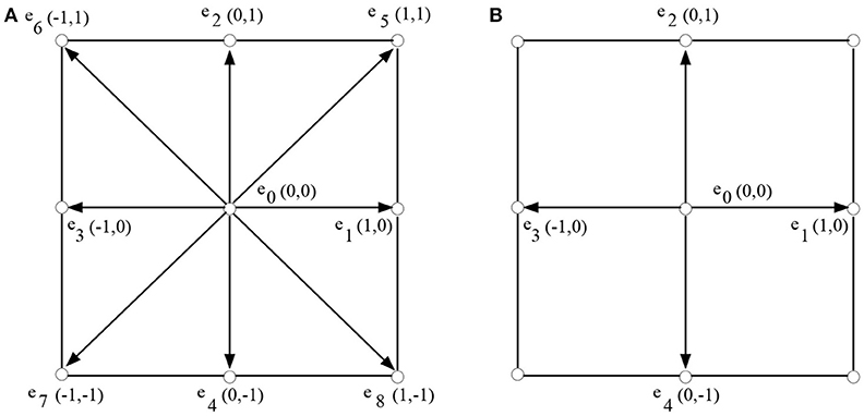
Figure 1. Lattice discrete velocity structure as in Trouette's paper (Trouette, 2013) (A) D2Q9 and (B) D2Q5 model.
In the above equation, is the lattice speed, where Δx = Δt = 1.
The macroscopic fluid density ρ and velocity u are obtained from the moments of the distribution function as follows:
3.2. Multiple-Relaxation-Time Thermal Lattice Boltzmann
Similarly, the MRT thermal LB equation for collision operation can be written as
where is the thermal distribution function. Here, the D2Q5 model has been used for the thermal LBM. The collision matrix N for D2Q5 is given as
The five eigen-values of S are all between 0 and 2. The diagonal collision matrix S can be written as
The values of si are given in detail in Trouette's paper (Trouette, 2013). They are
These parameters correspond to the thermal diffusivity
For the D2Q5 thermal LB model, a depends on the thermal diffusivity α and is less than 1 so as to avoid numerical instability.
Corresponding to the distribution function gi, the equilibrium moments meq are given as
In this case, for the 5-bit two dimensional (D2Q5) lattice, the discrete velocities are given as follows (see Figure 1B):
The temperature T can be calculated as
3.3. Application of the MRT-LBM to Convective Flows in a Square Cavity
To show the applicability of this MRT-LBM for porous media for convective flows, two cases have been considered: one is for natural convection flow and the other one is for mixed convection flow. (i) In the cases of natural convection flow, a 2D square cavity is filled with porous media in which the top and bottom walls are adiabatic but the left and right walls are isothermal and are maintained at different temperatures Th and Tc, respectively. Here, Th = 1.0 and Tc = 0.0, which is shown in Figure 2A. (ii) In Figure 2B, for the mixed convection flow, the top wall moves along the horizontal direction and is maintained at a constant temperature Th = 1.0, and at the bottom wall, Tc = 0.0. The left and right walls are adiabatic. For the present problem, the Boussinesq approximation is used in which all fluid properties are assumed to be constant, but the density that varies with temperature is allowed through the buoyancy term.
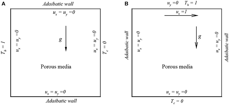
Figure 2. Schematic model for convective flows in square cavity: (A) natural convection and (B) mixed convection.
3.4. Boundary Conditions
For the no-slip wall, the bounce-back boundary condition is applied on velocity fields. Similar to what was observed in Trouette's paper (Trouette, 2013), the incoming unknown distribution function fi(xf, t+Δt) is equal to the outgoing post-collision distribution function :
For a wall with a fixed temperature Tw, the following boundary condition is applied for the D2Q5 model MRT thermal LB simulation:
For an adiabatic wall, the anti-bounce-back condition is applied:
3.5. Average Rate of Heat Transfer
In the heat transfer problem, the focus is on calculating the rate of heat transfer in terms of the local and average Nusselt numbers that are defined below, respectively:
For natural convection flow
and
For mixed convection flow
and
where H is the height and L is the lenght of the cavity.
4. Implementation of Forcing Term in MRT-LBM
The forcing term was implemented (11) by explicitly adding it with nine forcing moments as described by Guo and Shu (2008):
where, and .
With the above forcing moments, the collision process of MRT-LBM is implemented in moment space as
4.1. CUDA C Programming in GPU
CPU sequentially allocates the task to GPU and the whole numerical computation is done by GPU. The CUDA programming model mainly depends on the concept of the kernel. A kernel is a function that is executed in concurrent threads on the GPU. In NVIDIA Tesla k40 architecture, a maximum of 1,024 threads form a block, and blocks are grouped into execution grids (Figure 3). In CUDA, there are two programming languages, one is CUDA FORTRAN and the other one is CUDA C (or C++). In this study, we used CUDA C, which is a slight modification of the C programming language (NVIDIA, 2017). For example, in CUDA C programming, a new keyword is introduced as __global__ for the device (GPU) code, and this function is called from the main code using a triple angle < < < …>>>. The heterogeneous simulation system in a CUDA code can be classified into four categories (Obrecht et al., 2011): (i) sequential functions run by the CPU, (ii) launching functions allowing the CPU to start a kernel, (iii) kernel run by GPU, and (iv) auxiliary functions that are inlined to the kernel at the time of compiling.
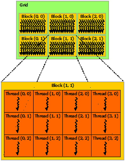
Figure 3. CUDA programming: grid of thread blocks (Source: NVIDIA).
At the run-time, the execution grid's layout is specified, and a grid may have up to three dimensions. The blocks of threads within a grid must be identical, and the threads are identified with respect to the grid using the two structures theardIdx and blockIdx, containing the three fields x, y, and z. A block may only be executed on a single streaming multiprocessor that yields an upper bound of the number of threads within a block; in a Tesla k40, this is a maximum of 1,024. In the present CUDA code, the following grid layout is used:
Here, we have given the streaming part of the CUDA C program:
Double precision enables (Computing capability 3.5) a Tesla k40 NVIDIA graphics card (Table 1) that is used for GPU computation, and the PGI FORTRAN compiler is used for CPU computation.
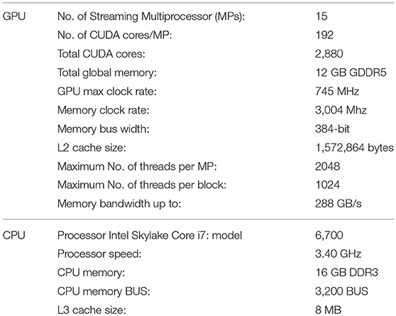
Table 1. Features of the Tesla k40 GPU device and the host CPU.
4.2. Data Structure Modification: AoS to SoA
One of the most important changes of the data structure modification in the GPU code is the change from array of structure (AoS) to structure of array (SoA). In CPU based LBM code, the data layout of the distribution function is usually arranged as AoS, because CPU can use cache memory. For example, the distribution function fi(x, t) is stored with the index (i+9 × x+9 × Nx×y) for the D2Q9 model, as depicted in Figure 4. But GPU functioning is based on the single instruction multiple threads (SIMT) execution model. In CUDA C, to meet the requirement of coalescing memory access, the data layout should be changed to SoA in LBM implementation. Later, the distribution function fi(x, t) is stored with the index (x+Nx×y+Nx×Ny×i) so that the parallel threads running the same instruction can access consecutive locations in memory (Delbosc et al., 2014; Xu et al., 2017).
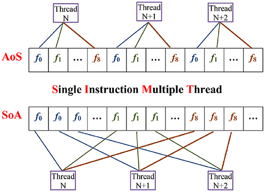
Figure 4. Data structure of AoS and SoA.
5. Results and Discussion
In this paper, a new approach is proposed for the convective heat transfer from the fluid saturated porous media using the GPU parallel computing via the CUDA C platform. Before conducting the main simulation, the present CUDA C code was validated for the lid-driven cavity flow, natural convection flow for side-heated square cavity, and mixed convection lid-driven cavity flow. The different cases are given below:
5.1. Lid-Driven Cavity Flow for Re = 10,000 and 20,000
Firstly, the MRT-LBM code is validated only for fluid flow simulation by considering the benchmarked lid-driven cavity flow, and then the double MRT-LBM code is validated for the natural and mixed convection flows in a square cavity flow. The results of the lid-driven cavity flow are depicted in Figures 5, 6 for Re = 10,000 and 20,000, respectively. The 1, 024 × 1, 024 lattice size is considered for both the Reynolds numbers. For Re = 10, 000, the results are compared with the results of Ghia et al. (1982), and the results for Re = 20, 000 are compared with the results of Erturk et al. (2005). The center of the primary vortex is located at (x, y) = (0.5119, 0.5271) and (0.5081, 0.5291) for Re = 10, 000 and 20,000, respectively, and the corresponding locations were found by Erturk et al. (2005) are (0.5117, 0.5300) and (0.5100, 0.5267). From these figures, it is clear that the agreement between the present and previous simulations is quite excellent.
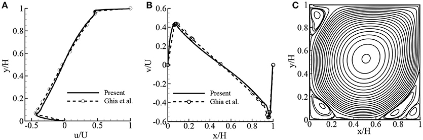
Figure 5. Comparison of the lid-driven cavity flow with the results of Ghia et al. (1982) (finite difference solutions): (A) u/U- velocity at mid x/H, (B) v/U- velocity at mid y/H, and (C) streamlines while Re = 10, 000 after 2,000,000 iterations.
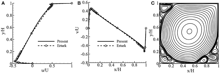
Figure 6. Comparison of the lid-driven cavity flow with the results of Erturk et al. (2005) (finite difference solutions): (A) u/U- velocity at mid x/H, (B) v/U- velocity at mid y/H, and (C) streamlines while Re = 20, 000 after 5,000,000 iterations.
5.2. Natural Convection Flow in Square Cavity for Ra = 103 to 109
The dimensionless quantities governing this problem are the Prandtl number and the Rayleigh number . In the simulation, the fluid velocity is normalized by the characteristic velocity , and the dimensionless temperature is θ = (T−Tc)/(Th−Tc).
In order to validate fluid flow and heat transfer, the MRT-LBM results in terms of the average Nusselt number, , obtained from the simulations are compared with the available data of SRT-LBM (Seta et al., 2006a), finite difference data of de Vahl Davis (1983), and finite element data of Nithiarasu et al. (1997) for the clear fluid (Pr =0.71) in a side-heated square cavity under the same boundary conditions for the laminar flow, where 103 ≤ Ra ≤ 106. For the transition to turbulent flows, the present results are also compared with the available results of SRT-LBM of Vishnampet et al. (2011) and Dixit and Babu (2006), and the spectral method of Le Quéré (1991), where the Ra ranges from 107 to 109. In these cases, the Darcy number Da = 108 and the porosity ϵ = 0.9999 have been considered. The results are given in Table 2, and shows compliance to Ra = 108. For Ra = 109, the average Nusselt number of Dixit and Babu (2006) is 57.35, but in the present case it is 54.56.
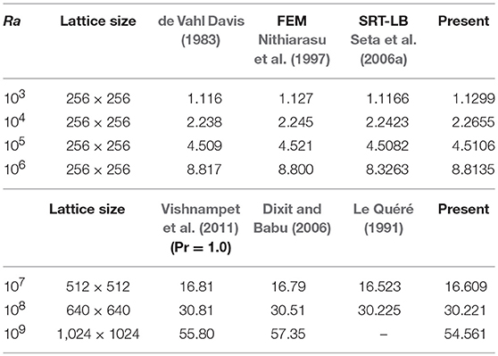
Table 2. Comparison of the present results in terms of the average Nusselt number, , with pure fluid results for Pr = 0.71, Da = 108, and ϵ = 0.9999.
Figures7A–C depicts the streamlines and isotherms for the transition to turbulent flows while Pr = 0.71 and Ra = 107 to Ra = 109 when Da = 108 and ϵ = 0.9999. From these figures, it is clearly seen that the pattern of the streamlines and isotherms for Ra = 107 and 108 coincides with the available results in the literature, but for Ra = 109, it varies slightly; because the results of Ra = 107 and 108 are for transitional flows, but the flow is turbulent for Ra = 109 ( Dixit and Babu, 2006).
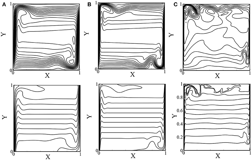
Figure 7. Streamlines (top) and isotherms (bottom) for pure fluids for Pr = 0.71: (A) Ra = 107, (B) Ra = 108, and (C) Ra = 109 while ϵ = 0.9999 and Da = 108.
5.3. Natural Convection Flow With Porous Media for Ra = 103 to 1010
In Table 3, the present numerical results are compared with the previous experimental results of Sathe et al. (1987) for different values of Ra, Pr, and Da while the aspect ratio A = 10. The comparison shows excellent compliance, and the maximum error is 2.2%. So, the present MRT-LBM method is suitable for simulating the flow phenomena and heat transfer for the porous media.
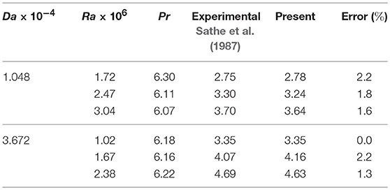
Table 3. Comparison of the present average Nusselt number, for ϵ = 0.5, with the previous experimental results of Sathe et al. (1987) in a tilled cavity with porous media while the aspect ration A = 10.
The streamlines and isotherms for the low Rayleigh number, Ra ranges from 103 to 106 while Da = 10−2 and ϵ = 0.6, are depicted in Figures 8A–D. For Da = 10−2, the fluid flow resembles a clear fluid where conduction dominates for Ra = 103 and convection dominates for higher Ra values. Figures 9A–D shows the streamlines and isotherms for the relatively high Rayleigh number with Darcy (Da ≤ 10−6) and non-Darcy (Da≥10−4) regimes while ϵ = 0.4. The pattern of the streamlines and isotherms are clearly different for the Darcy and non-Darcy regions and they are qualitatively similar to the results of Dixit and Babu (2006).
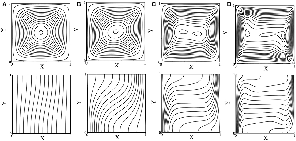
Figure 8. Streamlines (top) and isotherms (bottom): (A) Ra = 103, (B) Ra = 104, (C) Ra = 105, and (D) Ra = 106 while Pr = 1.0, Da = 10−2, and ϵ = 0.6.
Figure 9. Streamlines (top) and isotherms (bottom) for (A) Da = 10−2, Ra = 105, (B) Da = 10−4, Ra = 107, (C) Da = 10−6, Ra = 109, and (D) Da = 10−7, Ra = 1010 while Pr = 1.0 and ϵ = 0.4.
The effects of the Rayleigh number on the velocity distribution are depicted in Figures 10A,B while Da = 10−2 and ϵ = 0.4. It is seen that the velocity increases while increasing the Rayleigh numbers. For both velocity distributions, the larger velocity occurs near the walls, and the minimum velocity occurs at the center of the cavity where minimum values of the stream function occur. The local rate of heat transfer in terms of the local Nusselt number Nu is illustrated in Figures 11A,B for different values of Ra while Da = 10−2 and ϵ = 0.4 and for different values of Da while Ra = 109 and ϵ = 0.6, respectively. The local Nusselt number increases while increasing the Rayleigh numbers, but the local Nu decreases while decreasing the Darcy numbers.
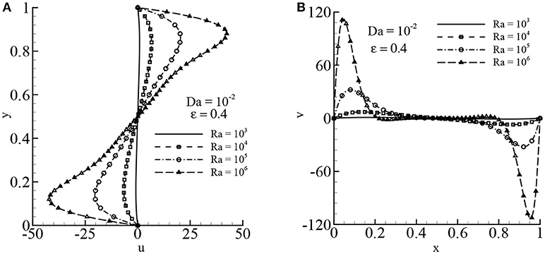
Figure 10. Velocity distribution: (A) u-velocity and (B) v-velocity for different values of Ra while Pr = 1.0, Da = 10−2, and ϵ = 0.4.
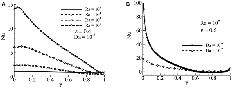
Figure 11. Local Nusselt number Nu for (A) different Ra values while Da = 10−2 and ϵ = 0.4 and (B) different Da value while Ra = 109, Pr = 1.0, and ϵ = 0.6.
In Table 4, the average Nusselt number, , has been inserted for different values of Ra = 103 to 1010, Darcy number Da = 10−2 to 10−7, and the porosity ϵ = 0.4 and 0.6. The results obtained by the present MRT-LBM are compared with the results obtained by the FEM of Nithiarasu et al. (1997), SRT-LBM of Guo and Zhao (2005), and the SRT-LBM of Vishnampet et al. (2011). The comparison shows that the excellent compliance. A set of new results for very high and very small Darcy numbers are presented in Table 4 at the bottom. For ϵ = 0.4 and 0.6, the average Nusselt number increases while the Rayleigh number increases from Ra = 108 to 1010 keeping the Darcy number fixed at Da = 10−7.
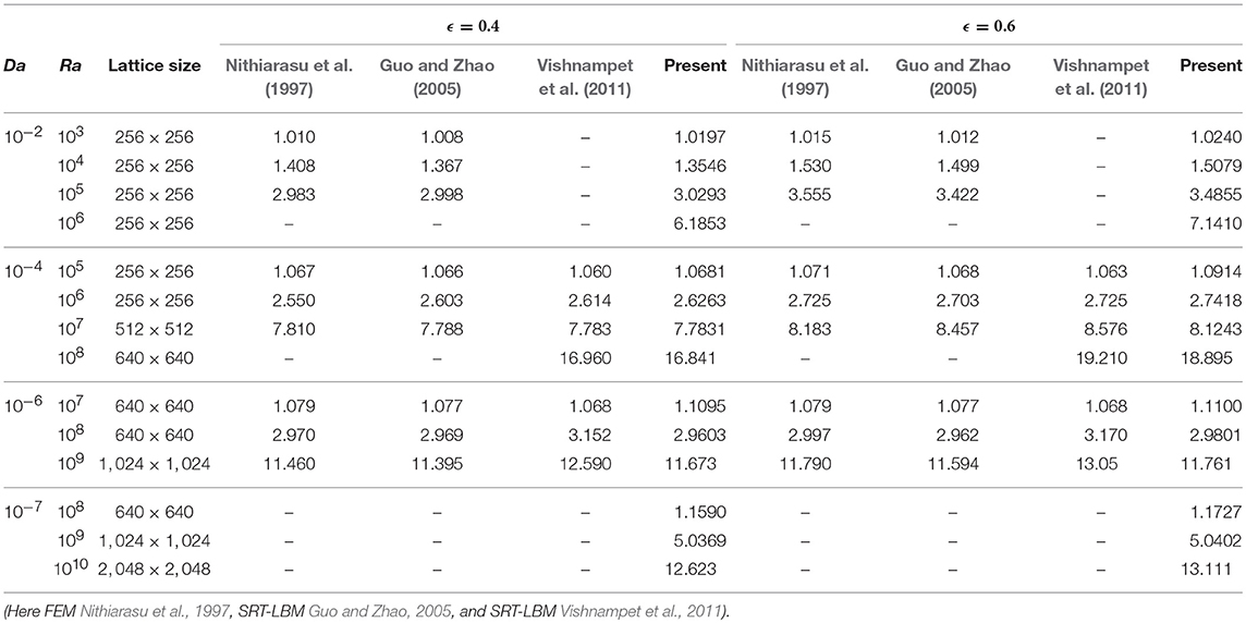
Table 4. The average Nusselt number, , with the Brinkman–Forchheimer model for Pr =1.0.
5.4. Mixed Convection Flow in a Lid-Driven Square Cavity
In the mixed convection case, the fluid velocity is non-dimensionalized by the lid velocity U = 0.1, and the temperature is similar to natural convection flow. Firstly, the code is validated while the heated lid is moving along the x-direction in pure fluid case, considering Gr = 100 and Re = 100, 400, and 1,000. Figures 12A–C show the velocity and temperature distribution, respectively, while Re = 400, Gr = 100, Da = 108, and ϵ = 1. The comparison of these velocity and temperature distributions with the results (Iwatsu et al., 1993; Khanafer and Chamkha, 1999) shows an excellent compliance. Another comparison has been made with regard to the average Nusselt number, , that is shown in Table 5 for the three different Reynolds numbers, Re = 100, 400, and 1,000, and Gr = 100. The agreement of the average Nusselt number with the availbale results of Iwatsu et al. (1993), Khanafer and Chamkha (1999); Khanafer et al. (2007), Abdelkhalek (2008), Tiwari and Das (2007), and Kefayati et al. (2012) is quite acceptable.
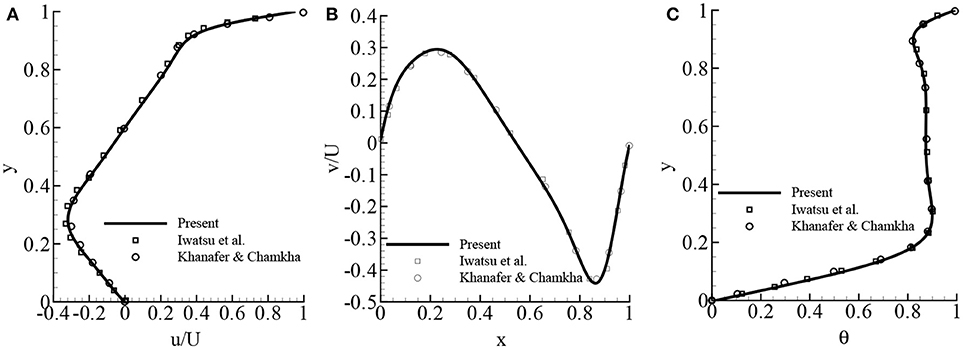
Figure 12. Comparison of the present study's mixed convection results with the available results of Iwatsu et al. (1993) and Khanafer and Chamkha (1999): (A) u/U velocity, (B) v/U velocity, and (C) temperature θ while Re = 400 , Gr = 100, Pr = 0.71, and no porous media.
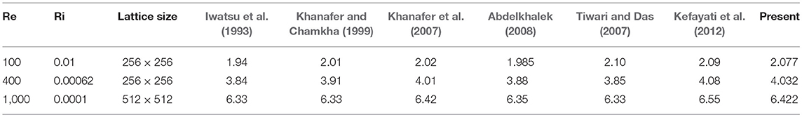
Table 5. Mixed convection: comparison of the average Nusselt number, , with the available numerical results of Iwatsu et al. (1993), Khanafer and Chamkha (1999); Khanafer et al. (2007), Abdelkhalek (2008), Tiwari and Das (2007), and Kefayati et al. (2012) for Gr = 100 and Pr = 0.71.
Figures 13A–D depict the streamlines (top) and isotherms (bottom) for the two different Reynolds numbers while Pr = 0.71 and Gr = 100. For Re = 400 and 1,000, there are three vortexes: primary, secondary, and tertiary. The primary vortex spans the whole cavity except the bottom right and left corners. In the isotherms, it is seen that the maximum temperature occurs near the top wall and the minimum at the bottom wall, and, qualitatively, these results agree with the results of Iwatsu et al. (1993) and Khanafer and Chamkha (1999).
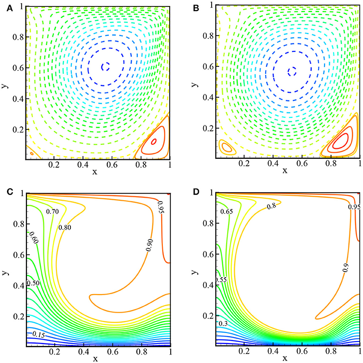
Figure 13. Streamlines (top): (A) Re = 400 and (B) Re = 1, 000 and isotherms (bottom): (C) Re = 400 and (D) Re = 1, 000 while Pr = 0.71 and no porous media.
5.5. Mixed Convection Flow in Lid-Driven Square Cavity With Porous Media
The effects of the Darcy number, Da, on the flow field and temperature distribution is illustrated in Figures 14A–C while Re = 400 and ϵ = 0.4. From the frame (a) and (b), it is observed that u at x = 0.5 and v at y = 0.5 decrease for decreasing Darcy numbers. It is obvious, for the smaller values of Da, that increasing the porous matrix inside the cavity delays the fluid motion. But the temperature, theta, at x = 0.5 is enhanced for smaller values of Da. Figures 15A–D depict the streamlines (top) and isotherms (bottom) for the two different porosities ϵ = 0.4 and 0.6 while Gr = 100 and Re = 1, 000. From the frames of the streamlines and isotherms, it is clearly seen that the effect of porosity in the porous media is significant. Changing the porosity from ϵ = 0.4 to ϵ = 0.6 changes the distribution of the stream function and isotherms that in turn will change the rate of heat transfer. For the large value of ϵ = 0.6, the center of the primary vortex shifted to the top right corner with an increase in the temperature of the fluid inside the cavity.
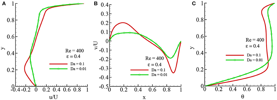
Figure 14. Velocity and temperature distibution for different values of Da: (A) u/U-velocity, (B) v/U and -velocity, and (C) temperature θ while Re = 400, Gr = 100, Pr = 1, and ϵ = 0.4.
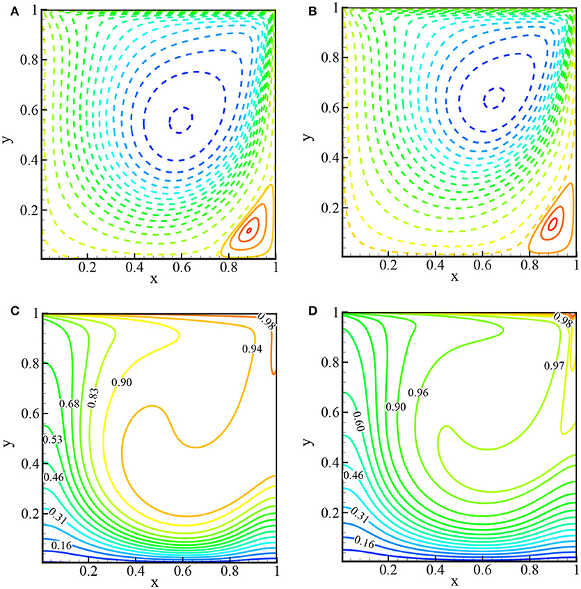
Figure 15. Streamlines (top): (A) ϵ = 0.4 and (B) ϵ = 0.6 and isotherms (bottom): (C) ϵ = 0.4, and (D) ϵ = 0.6 while Re = 1, 000, Gr = 100, Pr = 1, and Da = 10−2.
The average Nusselt number, , is inserted in Table 6 for different values of Reynolds number, Re, Darcy number, Da, and for ϵ = 0.4 and 0.6 while Gr = 100. For higher Re, the increases, but for decreasing Da, the average rate of heat transfer is reduced. The effects of porosity are also significant in the rate of heat transfer. The average rate of heat transfer decreases for increasing values of porosity ϵ, which contradicts what is observed with natural convection.
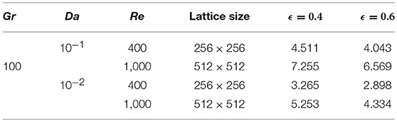
Table 6. Mixed convection case: the average Nusselt number, , with the Brinkman–Forchheimer model for Pr =1.0.
5.6. GPU Performance Over CPU
Table 7 shows a comparison of the GPU parallel performance over a sequential CPU performance in terms of the simulation time per iteration step. The GPU performance is higher than the CPU performance, and the speed up is calculated as the ratio of CPU simulation time over GPU time. From this table, it is interesting to see that for a 128 × 128 lattice size, the simulation in GPU is approximately 19 times faster than the CPU, but for a 2,048 × 2,048 lattice, it is 144 times faster. The performance of the GPU implementation strongly depends on the grid size. So, for larger grid problems, the GPU performance is better than the lower grid size.
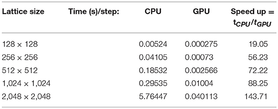
Table 7. MRT-LBM simulation time in CPU and GPU for different mesh arrangements.
Achieving better numerical results using LBM requires larger computational grid size. This requirement is a crucial factor for the overall performance optimization. Since CPU has more latency in processor clock speed than GPU hardware, in the case of the smaller computational grid, the performance of the numeric model using sequential programming in CPU surpasses the model implemented in the GPU parallel computing environment. However, GPU has more throughput than CPU because of its many processor architectures, which are very suitable for parallel task execution of numerical calculations. The GPU hardware consists of an array of scalar processors, which are executed in a group predefined in terms of the GPU hardware. During the invocation of the parallel code in CUDA computing environment, the GPU hardware requires a minimum amount of grid size allocation in global memory bus to occupy all of its processors for a synchronized task execution. Lower latency in device to host memory transfer is seen in smaller grid allocation, which can potentially degrade the overall performance of the numerical analysis. This latency issue can be significantly evaded using larger grid allocation for hiding the memory issues by instantaneous data sharing among large amounts of scalar processors. Moreover, the memory latency issue can be avoided with the assignment of the larger grid for the numerical calculation. Thus, the overall performance can be improved by gradually incrementing the grid size of the numerical model. Also, the performance speed up becomes substantially better in GPU than CPU programs whenever the grid size is incremented. According to Lin et al. (2013), larger computational grids require more arithmetic operations that would hide the memory latency and, hence, show a greater parallel performance.
6. Conclusions
In this paper, a double MRT-LBM is proposed for the porous media with the Brinkman–Forchheimer extended Darcy model to simulate the natural and mixed convection flows in a square cavity. Numerical simulation has been done using the state-of-the-art GPU parallel computing via the CUDA C platform. For the porous media, the Brinkman–Forchheimer model is directly used as the source term through the equilibrium distribution function. This approach is completely new and differs from the approach used in the SRT-LBM. The numerical results for the natural convection case are computed for the wide range of Rayleigh numbers, 103 ≤ Re ≤ 1010, Darcy numbers 10−2 ≤ Da ≤ 10−7, and the porosity parameter ϵ = 0.4 and 0.6. In the mixed convectional case, the simulations are done for the Reynolds numbers Re = 400, 100 and Grashof number Gr = 100 with 10−1 ≤ Da ≤ 10−2.
For increasing Ra in natural convection and Re in mixed convection, the velocity increases, but in both cases, the velocity decreases while the Darcy number decreases. The average Nusselt number, , increases for increasing porosity ϵ in natural convection, but in mixed convection, the opposite phenomena occurred.
The present results are compared with the available results computed by the finite difference, FEM and SRT-LBM, and the comparison indeed shows better agreement. It is also well-known that the MRT-LBM is superior to SRT-LBM in terms of numerical stability. The forcing term is implemented by nine discrete forcing moments that are added separately with the moment's space. The approach proposed in the present study for porous media with MRT-LBM can be used for other applications in fluid flow and heat transfer simulations.
Using CUDA C, the existing MRT-LBM FORTRAN 90 code has been re-written for GPU parallel computing that speeds up the simulation significantly. To be precise, in this Tesla k40 GPU, it is 144 times faster than the core i7 CPU simulation with a 2, 048 × 2, 048 lattice size. The GPU is more efficient for larger grid problems than for smaller grid problems.
Author Contributions
MM and MH have done the all simulations and completed the first draft of writing. MK has helped to write the code in GPU using CUDA C and edited the writing. SS edited the manuscript.
Conflict of Interest Statement
The authors declare that the research was conducted in the absence of any commercial or financial relationships that could be construed as a potential conflict of interest.
Acknowledgments
MM gratefully acknowledges NVIDIA Corporation for granting the Tesla k40 GPU card and the PGI group for providing the University developer license of PGI Accelerator Fortran/C/C++ compiler for a Workstation in Linux. This research is conducted with financial support from North South University (NSU) Faculty Research Grant 2016–2017.
References
Abdelkhalek, M. (2008). Mixed convection in a square cavity by a perturbation technique. Comput. Mater. Sci. 42, 212–219. doi: 10.1016/j.commatsci.2007.07.004
Calore, E., Gabbana, A., Kraus, J., Pellegrini, E., Schifano, S., and Tripiccione, R. (2016). Massively parallel lattice–Boltzmann codes on large GPU clusters. Parallel Comput. 58, 1–24. doi: 10.1016/j.parco.2016.08.005
Chai, Z.-H., Shi, B.-C., and Lin, Z. (2006). Simulating high Reynolds number flow in two-dimensional lid-driven cavity by multi-relaxation-time lattice Boltzmann method. Chin. Phys. 15:1855. doi: 10.1088/1009-1963/15/8/038
Chen, F., Xu, A., Zhang, G., and Li, Y. (2011). Multiple-relaxation-time lattice Boltzmann model for compressible fluids. Phys. Lett. A 375, 2129–2139. doi: 10.1016/j.physa.2015.01.067
de Vahl Davis, G. (1983). Natural convection of air in a square cavity: a bench mark numerical solution. Int. J. Numer. Methods Fluids 3, 249–264. doi: 10.1002/fld.1650030305
Delbosc, N., Summers, J. L., Khan, A., Kapur, N., and Noakes, C. J. (2014). Optimized implementation of the Lattice Boltzmann Method on a graphics processing unit towards real-time fluid simulation. Comput. Math. Appl. 67, 462–475. doi: 10.1016/j.camwa.2013.10.002
d'Humières, D. (1992), “Generalized lattice Boltzmann Equations, Rarefied Gas Dynamics: Theory and Simulations,” in Progress in Astronautics and Aeronautics Vol. 159, eds B. D. Shizgal and D. P. Weaver (Washington, DC: AIAA), 450–458.
Dixit, H. N., and Babu, V. (2006). Simulation of high Rayleigh number natural convection in a square cavity using the lattice Boltzmann method. Int. J. Heat Mass Trans. 49, 727–739. doi: 10.1016/j.ijheatmasstransfer.2005.07.046
Du, R., and Liu, W. (2013). A new multiple-relaxation-time lattice Boltzmann method for natural convection. J. Sci. Comput. 56, 122–130. doi: 10.1007/s10915-012-9665-9
Du, R., Shi, B., and Chen, X. (2006). Multi-relaxation-time lattice Boltzmann model for incompressible flow. Phys. Lett. A 359, 564–572. doi: 10.1016/j.physleta.2006.07.074
Erturk, E., Corke, T. C., and Gökçöl, C. (2005). Numerical solutions of 2-D steady incompressible driven cavity flow at high Reynolds numbers. Int. J. Numer. Methods Fluids 48, 747–774. doi: 10.1002/fld.953
Fattahi, E., Farhadi, M., Sedighi, K., and Nemati, H. (2012). Lattice Boltzmann simulation of natural convection heat transfer in nanofluids. Int. J. Therm. Sci. 52, 137–144. doi: 10.1016/j.ijthermalsci.2011.09.001
Ghia, U. G., Ghia, K. N., and Shin, C. T. (1982). High-Re solutions for incompressible flow using the Navier-Stokes equations and a multigrid method. J. Comp. Phys. 48, 387–411.
Guo, X., Zhong, C., Zhuo, C., and Cao, J. (2014). Multiple-relaxation-time lattice Boltzmann method for study of two-lid-driven cavity flow solution multiplicity. Theor. Comput. Fluid Dyn. 28, 215–231. doi: 10.1007/s00162-013-0312-y
Guo, Y., Bennacer, R., Shen, S., Ameziani, D., and Bouzidi, M. (2010). Simulation of mixed convection in slender rectangular cavity with lattice Boltzmann method. Int. J. Numer. Methods Fluids 20, 130–148. doi: 10.1108/09615531011008163
Guo, Z., and Shu, C. (2008). Lattice Boltzmann Method and Its Application in Engineering, Vol. 3. Singapore: Mainland Press Pte Ltd.
Guo, Z., and Zhao, T. S. (2002). Lattice Boltzmann model for incompressible flows through porous media. Phys. Rev. E Stat. Nonlin. Soft Matter Phys. 66:036304. doi: 10.1103/PhysRevE.66.036304
Guo, Z., and Zhao, T. S. (2005). A lattice Boltzmann model for convection heat transfer in porous media. Numer. Heat Trans. 47, 157–177. doi: 10.1080/10407790590883405
Iwatsu, R., Hyun, J. M., and Kuwahara, K. (1993). Mixed convection in a driven cavity with a stable vertical temperature gradient. Int. J. Heat Mass Transfer 36, 1601–1608.
Kefayati, G., Hosseinizadeh, S., Gorji, M., and Sajjadi, H. (2012). Lattice Boltzmann simulation of natural convection in an open enclosure subjugated to water/copper nanofluid. Int. J. Therm. Sci. 52, 91–101. doi: 10.1016/j.ijthermalsci.2011.09.005
Khanafer, K. M., Al-Amiri, A. M., and Pop, I. (2007). Numerical simulation of unsteady mixed convection in a driven cavity using an externally excited sliding lid. Eur. J. Mech. B/Fluids 26, 669–687. doi: 10.1016/j.euromechflu.2006.06.006
Khanafer, K. M., and Chamkha, A. J. (1999). Mixed convection flow in a lid-driven enclosure filled with a fluid-saturated porous medium. Int. J. Heat Mass Transfer 42, 2465–2481.
Ladd, A. J. C. (1997). Sedimentation of homogeneous suspensions of non-Brownian spheres. Phys. Fluids 9, 491–499.
Lallemand, P., and Luo, L. S. (2000). Theory of the lattice Boltzmann method: dispersion, dissipation, isotropy, Galilean invariance, and stability. Phys. Rev. E 61:6546. doi: 10.1103/PhysRevE.61.6546
Le Quéré, P. . (1991). Accurate solutions to the square thermally driven cavity at high Rayleigh number. Comput. Fluids 20, 29–41.
Lin, L.-S., Chang, H.-W., and Lin, H.-W. (2013). Multi relaxation time lattice Boltzmann simulations of transition in deep 2D lid driven cavity using GPU. Comput. Fluids 80, 381–387. doi: 10.1016/j.compfluid.2012.01.018
Mezrhab, A., Moussaoui, M. A., Jami, M., Naji, H., and Bouzidi, M. (2010). Double MRT thermal lattice Boltzmann method for simulating convective flows. Phys. Lett. A 374, 3499–3507. doi: 10.1016/j.physleta.2010.06.059
Moussaoui, M. A., Jami, M., Mezrhab, A., and Naji, H. (2010b). Computation of heat transfer and fluid flow in an obstructed channel using lattice Boltzmann method. Engn. Comput. 27, 106–116. doi: 10.1108/02644401011008540
Moussaoui, M. A., Jami, M., Mezrhab, A., Naji, H., and Bouzidi, M. (2010a). Multiple-relaxation-time lattice Boltzmann computation of channel flow past a square cylinder with an upstream control bi-partition. Int. J. Numer. Methods Fluids 64, 591–608. doi: 10.1002/fld.2159
Nemati, H., Farhadi, M., Sedighi, K., Ashorynejad, H. R., and Fattahi, E. (2012). Magnetic field effects on natural convection flow of nanofluid in a rectangular cavity using the lattice Boltzmann model. Sci. Iran. 19, 303–310. doi: 10.1016/j.scient.2012.02.016
Nithiarasu, P., Seetharamu, K. N., and Sundararajan, T. (1997). Natural convective heat transfer in a fluid saturated variable porosity medium. Int. J. Heat Mass Transfer 40, 3955–3967.
NVIDIA (2017). Compute Unified Device Architecture Programming Guide, version 7.5, 20 March 2017. CUDA Developer Zone, NVIDIA. Available online at: http://docs.nvidia.com/cuda/cuda-c-programming-guide/#axzz4eZNceJtc
Obrecht, C., Kuznik, F., Tourancheau, B., and Roux, J.-J. (2011). A new approach to the lattice Boltzmann method for graphics processing units. Comput. Math. Appl. 61, 3628–3638. doi: 10.1016/j.camwa.2010.01.054
Premnath, K. N., and Pattison, M. J. (2005). Computation of MHD Flows Using the Lattice Boltzmann Method. Santa Barbara, CA: MetaHeuristics, LLC.
Ren, Q., and Chan, C. L. (2016a). Natural convection with an array of solid obstacles in an enclosure by lattice Boltzmann method on a CUDA computation platform. Int. J. Heat Mass Transfer 93, 273–285. doi: 10.1016/j.ijheatmasstransfer.2015.09.059
Ren, Q., and Chan, C. L. (2016b). Numerical study of double-diffusive convection in a vertical cavity with Soret and Dufour effects by lattice Boltzmann method on GPU. Int. J. Heat Mass Transfer 93, 538–553. doi: 10.1016/j.ijheatmasstransfer.2015.10.031
Ren, Q., and Chan, C. L. (2016b). GPU accelerated numerical study of PCM melting process in an enclosure with internal fins using lattice Boltzmann method. Int. J. Heat Mass Transfer 100, 522–535. doi: 10.1016/j.ijheatmasstransfer.2016.04.059
Sathe, S. B., Tong, T. W., and Faruque, M. A. (1987). Experimental study of natural convection in a partially porous enclosure. J. Thermophys. 1, 260–267.
Seta, T., Takegoshi, E., Kitano, K., and Okui, K. (2006b). Thermal lattice Boltzmann model for incompressible flows through porous media. J. Therm. Sci. Technol. 1, 90–100. doi: 10.1299/jtst.1.90
Seta, T., Takegoshi, E., and Okui, K. (2006a). Lattice Boltzmann simulation of natural convection in porous media. Math. Comput. Simul. 72, 195–200. doi: 10.1016/j.ijthermalsci.2010.11.010
Shan, X., and Chen, H. (1994). Simulation of nonideal gases and liquid-gas phase transitions by the lattice Boltzmann equation. Phys. Rev. E 49:2941.
Tiwari, R. K., and Das, M. K (2007). Heat transfer augmentation in a two-sided lid-driven differentially heated square cavity utilizing nanofluids. Int. J. Heat Mass Transfer 50, 2002–2018. doi: 10.1016/j.ijheatmasstransfer.2006.09.034
Trouette, B. (2013). Lattice Boltzmann simulations of a time-dependent natural convection problem. Comput. Math. Appl. 66, 1360–1371. doi: 10.1016/j.camwa.2013.07.024
Vishnampet, R., Narasimhan, A., and Babu, V. (2011). High Rayleigh number natural convection inside 2D porous enclosures using the lattice Boltzmann method. ASME J. Heat Transfer 133:062501. doi: 10.1115/1.4003534
Wang, J., Wang, D., Lallemand, P., and Luo, L.-S. (2013). Lattice Boltzmann simulations of thermal convective flows in two dimensions. Comput. Math. Appl. 65, 262–286. doi: 10.1016/j.camwa.2012.07.001
Xu, A., Shi, L., and Zhao, T. (2017). Accelerated lattice Boltzmann simulation using GPU and OpenACC with data management. Int. J. Heat Mass Transfer 109, 577–588. doi: 10.1016/j.ijheatmasstransfer.2017.02.032
Ye, Y., Li, K., Wang, Y., and Deng, T. (2015). Parallel computation of entropic lattice Boltzmann method on hybrid CPU–GPU accelerated system. Comput. Fluids 110, 114–121. doi: 10.1016/j.compfluid.2014.06.002
Zhang, T., and Che, D. (2016). Double MRT thermal lattice Boltzmann simulation for MHD natural convection of nanofluids in an inclined cavity with four square heat sources. Int. J. Heat Mass Transfer 94, 87–100. doi: 10.1016/j.ijheatmasstransfer.2015.11.071
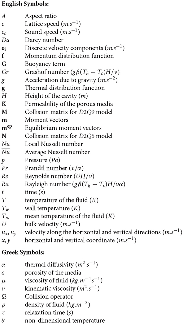
Nomenclature
English Symbols:
Keywords: GPU parallel computing, CUDA C, porous media, Brinkman–Forchheimer model, MRT-LBM, natural and mixed convection
Citation: Molla MM, Haque MJ, Khan MAI and Saha SC (2018) GPU Accelerated Multiple-Relaxation-Time Lattice Boltzmann Simulation of Convective Flows in a Porous Media. Front. Mech. Eng. 4:15. doi: 10.3389/fmech.2018.00015
Received: 11 July 2018; Accepted: 21 September 2018;
Published: 05 November 2018.
Edited by:
Satish Kumar, Georgia Institute of Technology, United StatesReviewed by:
Dipankar Chatterjee, Central Mechanical Engineering Research Institute (CSIR), IndiaAlex Hansen, Norwegian University of Science and Technology, Norway
Copyright © 2018 Molla, Haque, Khan and Saha. This is an open-access article distributed under the terms of the Creative Commons Attribution License (CC BY). The use, distribution or reproduction in other forums is permitted, provided the original author(s) and the copyright owner(s) are credited and that the original publication in this journal is cited, in accordance with accepted academic practice. No use, distribution or reproduction is permitted which does not comply with these terms.
*Correspondence: Md Mamun Molla, bWFtdW4ubW9sbGFAbm9ydGhzb3V0aC5lZHU=