 Yuanzhe Li1
 Noshir S. Pesika
 Yu Tian
- 1State Key Laboratory of Tribology, Department of Mechanical Engineering, Tsinghua University, Beijing, China
- 2Department of Chemical and Biomolecular Engineering, Tulane University, New Orleans, LA, United States
- 3School of Mechanical Engineering, Guangxi University of Science and Technology, Liuzhou, China
Energy-based and force-based approaches are two basic ways to establish an adhesion model. For the adhesion of tape-like thin films, the Kendall equation considers the overall energy balance but inherently contains little information of the peel zone geometry and stress distribution. The peel zone model provides an empirical approximate of the peel front from the approach of a force description and coincides well with experimental results for a wide range of peel angles. However, the peel-zone model itself has not been unified with the Kendall equation yet. We propose a two-layer spring contact tape peeling model which considers the balance between the stretching force of the backing layer and the adhesive force transferred through the adhesive layer. The model provides an analytic shape description of the curved bifurcation region of the peel front. An approximate analytic solution of the peel force reduces to the Kendall equation by considering a Kendall-like energy conservation critical criterion, which further supports the proposed model. Further analysis of the relationship between the length of the peel zone and the adhesive force provides insight into the validity of the peel zone model. The proposed model provides a new insight in the tape peeling process and mathematically builds a potential bridge between the Kendall model and the peel-zone model.
Introduction
Adhesion describes the common phenomenon that two well-contacted solids have the tendency to stick together due to van der Waals force or other intermolecular interactions. Adhesion is ubiquitous not only in daily life but also has many applications in industry (Sanchis et al., 2008; Yan et al., 2012; Liu et al., 2018), in the medical field (Falde et al., 2016; Labernadie et al., 2017) and even in biological systems (Arzt et al., 2003). One of the most famous examples is the gecko's unique ability to climb vertical walls and walk upside down on ceilings with the help of the strong adhesion force generated between the hairy pads at the end of gecko feet and the opposing surfaces (Autumn et al., 2000), which still draws interest in the biomimetic research community.
The geometry of contact bodies plays an important role in the macroscopic adhesion behaviors. For example, two solids surfaces in everyday-life generally show weak macroscopic adhesion. One of the most important reasons is that the roughness of surfaces hinders the intimate contact of the two bodies (Persson et al., 2005; Fan et al., 2011; Ciavarella, 2016). A spherical body and a thin film are two kinds of widely-used basic geometric models to describe the bulk adhesion and tape peeling behaviors, respectively. The classical approach to describe the adhesion force is to apply an energy balance (Popov et al., 2017; Popova and Popov, 2018), which assumes that the total energy of the adhesive system remains constant during adhesive contact process
where Ue is the elastic energy stored in the system, Up is the potential energy associated with the external force, and γ is the adhesion energy or the work to create new surface during peeling. Based on this principle, the Johnson-Kendall-Robert (JKR) model (Johnson et al., 1971; Kendall, 1971) is proposed to describe the adhesion interaction between elastic spherical bodies, and the Kendall equation (Kendall, 1975) is widely used to explain the relationship between the peel force and the peel angle of adhesive tape.
The energy balance approach is simple and effective to describe the adhesion force, but it inherently lacks detailed information about the shape of adhesive zone and the generation of the adhesion force. While the approach of force balance considers the adhesive force at the peel zone directly and provides more information about adhesion process. From the view of the spring contact model and based on the Method of Dimensionality Reduction (Popov and Heß, 2015; Lyashenko et al., 2016), the same results of spherical bodies contact adhesion can be obtained as those predicted by the JKR model. In the case of the tape peeling model, one important attempt based on the force balance approach is the peel zone (denoted as PZ) model (Tian et al., 2006; Pesika et al., 2007).
The PZ model assumes that the adhesive force is only generated at the peel zone during the tape detachment. The peeling process is also a common and important phenomenon in bulk adhesion (Zeng et al., 2016), not only in tape peeling (Heepe et al., 2017; Misseroni et al., 2018). Because of its simplicity and the insight that it can provide for a particular system, the PZ model has been widely applied and further developed (Molinari and Ravichandran, 2008; Zhou et al., 2011). However, the geometry of the peel zone in PZ model is an empirical assumption, and the tape stretching effect is not considered. One of the severest problems is the peel force predicted by the PZ model goes to infinity when the peel angle approaches zero, which is inconsistent with the Kendall equation and experimental results.
The difficulty to describe the tape peeling behaviors from the view of force balance is to precisely describe the geometry of peeling tape. One of the prior attempts involved the incorporation of the spring contact model (Sato and Toda, 2004), but the effect of the peel angle was not considered. In this work, we proposed a spring contact tape model derived from a similar two-layer spring model, but considers the effect of the peel angle and the complex boundary conditions associated with the system. One of the approximate analytic solutions is shown to be consistent with Kendall equation by considering an energy conservation critical criterion, which verifies the reliability of the proposed spring contact model. The verification of the assumptions of the PZ model based on the analysis of the calculated geometry of the peel zone region builds a potential bridge connecting the Kendall equation with the PZ model. The proposed model is a complement for the peeling model of thin adhesive film from the approach of a force balance.
Model
Discussions of the Original Peel Zone Models
The peel-zone models introduced in Tian et al. (2006) (denoted as Case 1 in the following discussion) and Pesika et al. (2007) (denoted as Case 2 in the following discussion) described the tape peeling process successfully from the view of force description. However, there are slight differences between the two models in physical images.
Generally, the peel zone is defined as a limited zone that exhibits an attractive force between the tape backing and the substrate. In Case 1, the tape backing is hard enough that the tape only shows bending deformation but without deformation in the thickness direction. The direct van der Waals interaction is considered between the tape backing and the substrate. Combined with the classical Lennard-Jones potential, the peel zone can be determined by the distance between the tape backing and the substrate (e.g., between ε0 and 5 ε0 in Figure 1A). Note that the equilibrium distance for intermolecular interaction, ε0, usually takes the value of ~0.3 nm. The peel zone in this case is in nano-scale.
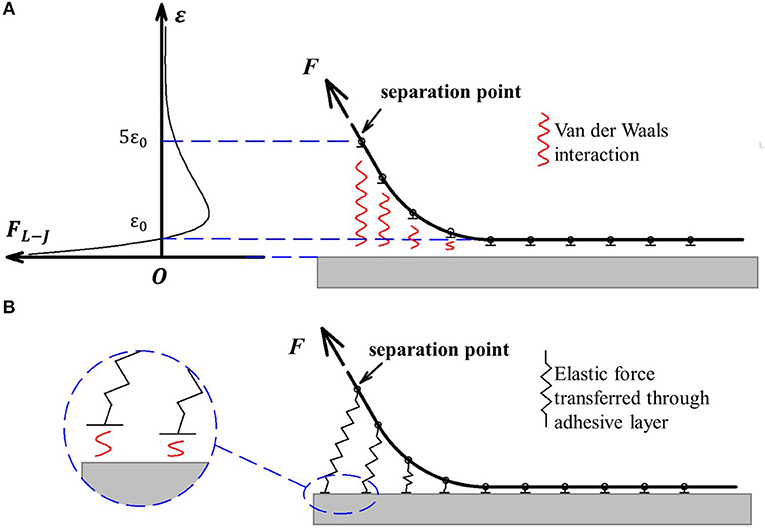
Figure 1. Physical imagines of the peel zone description in Case 1 and Case 2. (A) Case 1: direct Van der Waals interaction between the tape and the substrate. (B) Case 2:attractive force transferred through the adhesive layer.
In Case 2, the tape is soft so that the van der Waals force causes both the curvature of the backing and the deformation in the thickness direction. Typically, this kind of tape can be modeled by two independent layers, which include the backing layer for stretching and bending, and the adhesive layer for adhering. The stretching deformation of the adhesive layer is far greater than the range of van der Waals interaction, and thus the shape of the peel zone is mainly determined by the deformation of the adhesive layer. The adhesive force is transferred through the adhesive layer in the form of elastic force and the peel zone is magnified by the deformation of the adhesive layer (shown in Figure 1B). But essentially the adhesive force is generated by van der Waals interaction between the substrate and the end of the adhesive layer (shown in the insert in Figure 1B). In this case van der Waals force determines the adhesion strength in the form of interfacial energy.
If the energy dissipation within the tape is negligible and only the elastic force of the adhesive layer is considered, the energy conservation equation of the Kendall equation is still valid for both the two cases.
Note that for Case 2, this adhesive layer can be either physical entity or physical model. The former (e.g., commercial tape) type of adhesive layer usually consists of a soft thin layer of adhesive, the material of which is usually different from the backing layer. Whereas, the latter (e.g., dry-adhesion tape) type of adhesive layer is distinguished from the backing layer by the deformation. The backing layer mainly deforms in the peel force direction, and the adhesive layer deforms in the thickness direction. In this case the adhesive layer and backing layer are artificially divided from the same physical entity.
Spring Contact Tape Model
We established the spring contact tape model focusing on the Case 2. This kind of adhesive tape generally consists of two layers, which include the backing layer for stretching and adhesive layer for adhering. Considering the small thickness of the backing layer, the tape is considered infinitely flexible and the bending modulus of elasticity is neglected. When the tape peeling velocity is very small, the peeling process can be considered under a quasi-static state and there is always a force balance based on a Lagrangian description. The adhesion energy is also assumed to be independent of the peeling velocity. Tape deformation is assumed in the range of linear elasticity and the peel stress is smaller than the ultimate strength of the tape. The tape should be perfect without defect and peeled clearly from the substrate.
In this model, the adhesive layer is modeled by a series of elastic springs which are bonded between the tape backing and the substrate to transferred the adhesive force. Here the elastic spring is to present the elastic deformation in thickness direction. Considering that the displacement change induced by the intermolecular interaction is much smaller than the elastic deformation, the force-displacement relationship of the adhesive layer is still considered to approximately satisfy the Hooke's law. Whereas, van der Waals interaction acts as the interfacial energy to determine the adhesion strength, which in this model is the maximum strength of the elastic spring before detaching from the substrate.
On basis of these assumptions, the tape system can be modeled by two series of springs in two dimensions of the x-y plane as shown in Figure 2. The tape backing layer is evenly divided into N units of length dt. The units are represented by a set of end-to-end linear springs (A) with a spring constant K/dt. Here, K corresponds to the modulus of elasticity per unit length of the tape backing, and it can be represented as K = Ebh (E is the equivalent stretching modulus, b is the width of the tape backing, and h is the thickness of the tape backing). Note that b is assumed sufficiently large to consider the tape backing in plane strain conditions. In this case the equivalent elastic modulus will be used to consider the Poisson effect (Eb is the stretching modulus of the backing material and μ is the Poisson ratio). The adhesive layer is represented by a set of side-by-side linear springs (C) with a spring constant kdt, where k corresponds to the modulus of elasticity per unit length of the adhesive layer and can be represented as k = Eab/ξ (Ea is the stretching modulus of the adhesive material, and ξ is the thickness of the adhesive layer).
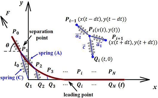
Figure 2. Schematic of the spring contact tape model.
When peeling the tape slowly, both the backing layer and adhesive layer stretch. The adhesive layer spring (C) stretches with one end connecting with the fixed point on the substrate (denoted as Qi) and the other end moving with flexible joint on the backing layer (denoted as Pi). In the coordinate system shown in the Figure 2, the coordinates of Qi are described as (t, 0) and the coordinates of Pi are described as (x(t), y(t)).
As assumed above, the tape is peeled quasi-statically and the force balance holds for each joint Pi at each moment. In order to obtain the shape of the curve of the peeling tape, the force balance at the joint Pi (1 ≤ i < N) (shown in the insert of Figure 2) is considered as follows
and it equals to
where vectors , and represent the springs connected with joint Pi, respectively (shown in the insert of Figure 2). The initial length of spring (A) is dt, whereas the initial length of spring (C) ξ is neglected when considering the relatively large elongation.
Here, , and . Considering N → ∞ and dt → 0, , . If the function of y and x is denoted as y = f(x), it follows that and .
Considering the x-direction component of Equation (3) [denoted as Eq. (3)], it follows that:
And the y-direction component is:
Let ẋ = dx/dt and ẏ = dy/dt. Denote that
Then Eqs. (4) and (5) can be written as
where is defined as adhesion factor with dimension of 1/m. We also denote that ṗ = dp/dt and.
Such parametric differential equations determine the curve of the shape of the peeling tape. The peel force F can be also expressed based on the force balance equation at the separation point P1 (shown in Figure 2) as:
The boundary conditions exist at both the left end and the right end, which are geometric boundary conditions and force boundary conditions, respectively. At the left end, the tape is detached from the substrate with a peeling force at a peeling angle θ. Therefore at the separation point (x(0), y(0)), the angle between the spring (A) direction and the substrate reaches the peeling angle θ, and the length of the spring (C) reaches the critical value l0, which describes the ultimate length of the adhesive layer at a certain peel angle. It follows that
As a natural boundary condition, assume that there is no force at the right end far away from the peeling point. Combined with Eq. (9), it can be described as
A special condition when the peel angle θ is zero can be calculated easily. Stretching only occurs in the x direction so that y = 0 and ẏ = 0. The differential equation Eq. (8-1) takes the form:
The solution is
Considering the boundary conditions, it follows that C1 = l0 and C2 = 0. Then the shape function of the peeling tape is calculated as:
The peel force , or
Note that the peel force derived by the Kendall equation is
When θ is zero, the peel force per unit width predicted by the Kendall equation is
Compared with Eq. (15), it can be obtained that
when the peel angle θ = 0. According to the Method of Dimensionality Reduction, there is a similar separation criterion for normal contact with adhesion
which is known as the rule of Heβ for the adhesive contact (Popov and Heß, 2015). Here a is the contact radius in the one-dimensional normal contact model. If we assume that the a can be replaced with an introduced equivalent peeling parameter in tape peeling that , Eq. (19) will take the same form with Eq. (18).
However if the determined constant λl0 in Eq. (18) is accepted for general situations that the peel angle θ is larger than zero, the predicted peel forces against the peel angles will be smaller than the predicted values of the Kendall equation. The reason is that for normal adhesive contact between bulk bodies, all springs separate from the substrate perpendicularly. However, for a thin film adhesion (tape peeling process), the springs separate from the substrate at a certain angle. In this case the equivalent peeling parameter atape is constant but the separation criterion should be dependent on the peeling angle θ.
Therefore, for a tape peeling process, the relationship of Eq. (18) or Eq. (19) need to be modified to consider the angle dependence. In the following section, an approximate analytical solution and a Kendall-like energy approach are proposed to determine the angle-depended separation criterion.
An Approximate Analytical Solution
An analytical solution to the above differential equations is not trivial. An approximate analytical solution can be obtained if the original length term of the tape backing is neglected when describing the differential unit in the shape function. Then Eq. (2) simplifies to
The differential equations take the following forms:
which can be solved as
Using the boundary condition (11-1), it follows that C2 = 0 and C4 = 0, which simultaneously satisfy the boundary condition (11-2). Moreover, Eqs. (22) also give us an explicit physical meaning of the defined adhesion factor λ. That is, 1/λ describes the characteristic decay length of the deformed zone. Physically, a large elastic modulus (a large K) of the tape backing induce a large 1/λ, which contributes to a large peel zone.
Using the boundary conditions (10-1) and (10-2), it follows that
which can be solved as
Thus, the shape function of the peeling tape takes the form of
The peel force F still takes the form of Eq. (9) as . Considering K = Ebh, it follows that
The following section describes how the parameter value is evaluated. Generally, there are two modes of the detachment failure of the adhesive tape, which is determined by the location of separation (Aubrey et al., 1969). One possible mode is “cohesive separation,” which is characterized by failure within the bulk of the adhesive layer and will induce damages in adhesive layer such as the cavitation and fibrillation. In this case, the critical length l0 is a certain value when neglecting the velocity effect and it is determined by the ultimate strength of the adhesive layer material. But more commonly the adhesive tape is peeled by separating cleanly from the substrate with little residue, which is referred to the “adhesive separation” mode. In this case the critical length l0 is not determined by its own strength but by the interfacial energy between the substrate and the adhesive. It means that l0 is not constant but changes with the peeling direction.
As we assumed that the tape is peeled without failure, it is more meaningful to focus on the condition of “adhesive separation.” However, it is difficult to describe the angle dependent property of the critical length of the adhesive layer from direct force description, since it will involve intermolecular interaction. A Kendall-like approach is used to obtain an approximate critical value. To avoid introducing the potential energy item related with the peel force, we must focus on a different peeling process from the Kendall equation.
We focus on the instant that the first spring of the adhesive layer is detached from the substrate, we assume that the other springs have no change yet (shown in Figure 3). In this case, the tape backing only rotates a small angle dθ around the point O, which induces that the movement of the peel force acting point, AA′, is nearly perpendicular to the direction of the force (shown in the insert of Figure 3). In this moment, the peel force F does not produce work, and the energy input is all provided by the elastic energy of the first detached spring. The tape backing is considered to be little deformed until a small length dt of the adhesive layer is detached from the substrate. Consider that this process is an energy conservation process, it follows that
where is the maximum elastic energy released from the detachment of the adhesive layer from the substrate, γbdt is the increase in the interfacial energy, and Kdt(1 − cosθ) is the approximate increase in elastic energy (Yu and Suo, 1998) stored in the backing layer.
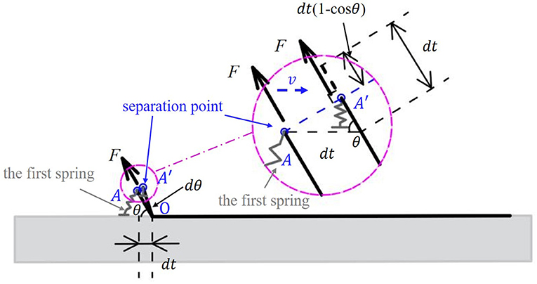
Figure 3. Schematic of the instant that the first spring of the adhesive layer is detached from the substrate.
For the last term in the equation, a rough approximation is given. Consider a spring with spring constant ks, the increased elastic energy for increased elongation dx takes the form as . For the tape backing, we have ks = K/x and roughly dx = dt(1 − cosθ). The approximate answer dE = K·dt(1−cosθ) is obtained. It should be noted that during the instant peeling process described above, the backing layer of the tape is compressed, which is very difficult to occur in real peeling experiments. This is because the tape is usually very thin and flexible, which easily buckles under pressure force. However, in this model the tape is modeled by springs and it does have the ability to be compressed and deform as an elastic material. Moreover, the above peeling process is instantaneous and unstable. The tape shows the potential to be compressed, but it is soon followed by stretching in a stable peeling process.
Consider , the Eq. (27) is equivalent to
Note that when the peel angle θ = 0, the result coincides with the non-approximate solution in Eq. (17). If the above relationship is still valid for a non-trivial peeling process, combined with Eq. (26) it follows that
which exactly reproduces the solution of the Kendall equation [the solution of Eq. (16)]. In other words, the Kendall equation can also be interpreted by this proposed spring contact tape model from the view of force balance, not only from the view of energy balance. In addition, the proposed model is capable of providing more information about peeling process like geometry profile and stress distribution.
Results and Discussion
Discussion About the Approximate Analytical Solution
The numerical solution of the model is calculated and compared to the approximate analytical solution of the model. The tape parameter values needed are obtained from a typical peeling process obtained from Reference (Pesika et al., 2007) [denoted as Pesika et al. (2007)] and listed in Table 1. Note that the stretching modulus E is absent in Pesika et al. (2007), and therefore the Kendall equation is used when θ = 0° as to estimate the value. The value Ea/ξ is estimate by γ = (Ea/2ξ)Rθ(1 − cosθ) when θ = 90° based on the PZ model.
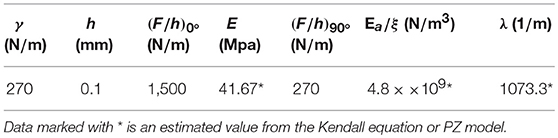
Table 1. Parameters determined by the experiments [cited from Pesika et al. (2007)] or derived from theoretical models.
The differential equations of the model [Eqs. (8-1) and (8-2)] are solved by “shooting method” to obtain the numerical solutions satisfying all the boundary conditions [Eqs. (10) and (11)]. Instead of the value t reaching infinity, the maximum t is set as 0.02 when conducting the numerical calculation. The results show no difference compared with the condition that the maximum t is set as 0.01, which means that here t = 0.02 is large enough to satisfy “infinite.” To simplify the calculation, the boundary condition Eq. (11-1) is replaced by x = t (t → 0.02), for the calculated results still satisfy ẋ2 + ẏ2 = 1 (t → 0.02).
The critical values of l0 are obtained when the peel forces against peel angles satisfy the Kendall equation. The relationships of the values and (1 − cosθ) are shown in Figure 4. Note that the relationship predicted by the approximate solution is a linear correlation [Eq. (28)]. The approximate analytical results coincide well with the numerical ones at small peel angles. There are small differences at large peel angles, because the relative small elongation cannot fully satisfy the model simplification conditions. Generally, the approximate analytical result is in good agreement with the full numerical solution.
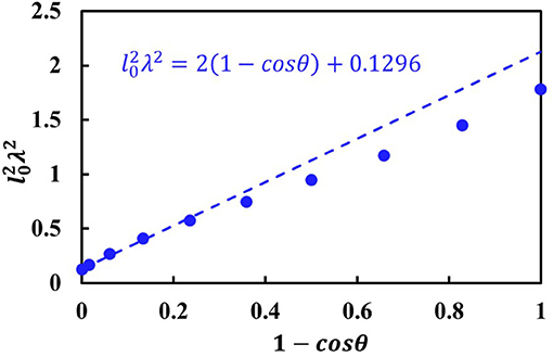
Figure 4. The relationship between and (1−cosθ). The data marked with circle are predicted by the numerical solution, and the dashed line is predicted by the approximate analytical solution.
The shape change of a peeling tape mainly occurs in the peel zone, the shape of which can be approximately described as a circular arc as shown in Figure 5A. In this work, the fitting circle is determined by satisfying tangents to both the peeling force at the separation point and the substrate. Both the approximate and the full model predict the same trends of fitting radii, which increases with the decrease of the peeling angle (shown in Figure 5B). The difference of the radius predicted by the approximate and full solution is under 15%, which means that the two models show no significant differences for predicting the shape of the peeling tape within the peel zone region.
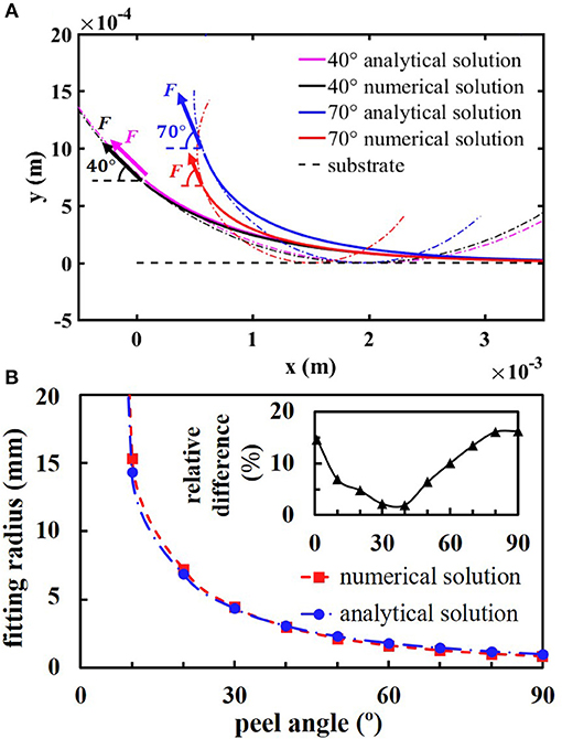
Figure 5. The prediction of the shape of tape at different peeling angle. (A) The shapes of the curve of the peeling tape with the fitting curves of the peel zone at peel angles 40 and 70°, respectively. (B) The radius of the fitting circle predicted by the numerical solution and the approximate analytical solution, respectively. The insert is the relative difference.
Neglecting the initial length of the differential unit has little effect on the geometry property of the peeling tape. However, the peel force predicted by the approximate solution based on Eq. (18) takes the form
which will show significant differences compared to the numerical solution [Eq. (9)]. For consistency, the modified parameters are introduced for compensating the initial length in the approximate model:
The original parameters C1 and C3 are used to calculate the approximate shape of the peeling tape. But when it comes to the calculation of the force, the modified parameters and should be used. For example, if C1 in Eq. (30) is replaced with , the peel force will coincide with Eq. (29). Based on these rules, the approximate model can provide reliable approximate analytical expressions of both geometry and stress of a peeling tape.
Explanations of the Peel-Zone Model
The basic principle of the PZ model is that the normal component of the peel force (the adhesive force) is only generated in the peel zone (shown in Figure 6) (Tian et al., 2006; Pesika et al., 2007). The original PZ model was established based on the three assumptions to simplify the problem (Pesika et al., 2007), which are as follows:
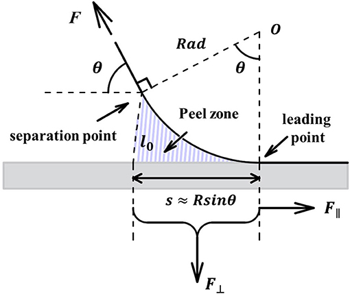
Figure 6. Schematic of the peel zone in the PZ model [modified from Pesika et al. (2007)].
(i) The shape of the curve of the tape backing is approximately circular in the all-important local region of the peel zone.
(ii) The separation point is assumed to remain at the same normal distance from the detaching surface for all peel angles θ.
(iii) The normal component of the peel force (the adhesive force), F⊥, generated in the peel zone is proportional to the area of the peel zone, i.e., F⊥ ∝ sb in Figure 6.
In the view of spring contact model, the three assumptions can be explained theoretically. But note that the peel-zone is only valid at large peel angle (i.e., θ ≥ 40°).
The coordinate of the separation point can be calculated by Eqs. (15) and (16) as (C1, C3). When a circular arc is used to fit the shape of the tape backing at the peel zone [assumption (i)], the radius of the fitting circle takes the forms
To evaluate the goodness of circle fit, the coefficient of determination R2 is calculated by
where and . The results show that all values of R2 are larger than 0.995, which indicates that a circle is a good approximation of the shape of the curve at the peel zone for the whole angles ranging from 0 to 90° (shown in the insert of Figure 7).
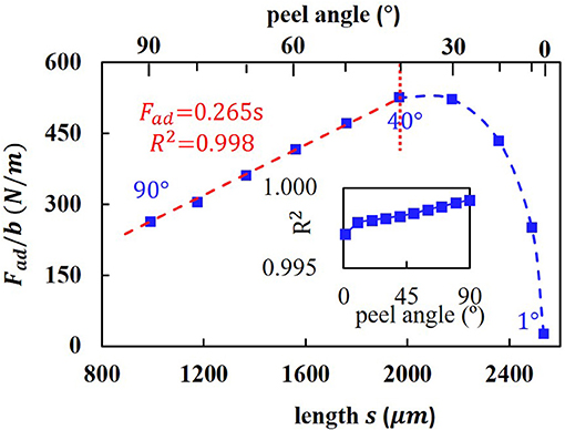
Figure 7. The relationships between the adhesive and the projected length of the peel zone. The insert is the coefficient of determination R2 when using a circle to fit the peel zone.
The assumption (ii) assumes that separation point remains at the same normal distance from the detaching surface. This can be explained that the springs of the adhesive layer are approximately perpendicular to the substrate in the real experiments so that the critical length l0 keeps constant. Based on this assumption, the area of the peel zone in assumption (iii) is the projected area of the peel zone and it can be described as S = sb = Rad*bsinθ. The adhesive force can be expressed as Fad = Fsinθ, the relationship of adhesive per unit Fad/b and s is shown in Figure 7. When the peel angle θ is larger than 40°, the adhesive force is nearly proportional to the projected area of the peel zone.
However, the PZ model fails to predict the peel force when the peel angle is small. This is because it neglects the stretching effect of the backing layer, so that the area of the peel zone will be overestimated and will even tend to be infinity when the peel angle reaches zero. Combined with the Eq. (30), the predicted projected area of the peel zone in this model S = Rad·bsin θ ∝ sin2θ/(1 − cosθ), which tends to be a finite value when the peel angle θ tends to be zero. However, based on the original PZ model, the radius of the peeling front Rad_PZ ∝ 1/(1 − cosθ) and the area of the peel zone S_PZ = Rad_PZ *bsinθ ∝ sinθ/(1 − cosθ) will tend to be infinity when the peel angle θ tends to be zero.
Applicability and Limitation of Proposed Model
In this work only the “adhesive separation” mode of the tape peeing is considered, which means the critical value l0 of the length of the spring (C) predicted by Eq. (28) is determined by the adhesion energy. But when the stretching strength of the adhesive layer is weaker than the adhesion strength at the interface, the separation occurs within the bulk of the adhesive layer. Given that the critical value l0 predicted by Eq. (28) increases with the peel angle, the critical value l0 may keep at a certain value and the tape failure may turn into the “cohesive separation” mode at a large peel angle (i.e., at θ > 60°). In this case, the energy-conservation based Kendall equation is not valid, considering the dissipation of energy in the adhesive layer. For the proposed model, the critical value l0 based on Eq. (28) can be modified to take the form as
Combined with the Eq. (26), the predicted peel force may be smaller at large peel angles compared with the Kendall equation, which is consistent with the experimental results recorded in Pesika et al. (2007).
Since this proposed spring contact model contains more information about force generation than the Kendall equation, it provides greater insight into the tape peeling process. The proposed model can be modified to apply to many complex situations. One meaningful modification is to consider the viscoelastic properties of polymers materials, which can significantly affect the peeling force as a function of the peeling velocity (Urahama, 1989). It is a valid approach to describe the viscoelastic adhesive layer by replacing the spring element (C) in Figure 2 with the Kelvin element, which is a parallel connection of spring and dashpot with spring constant k and viscosity η. In this case the force acting on the element is given as where ε(τ) is the time dependent displacement and is its time derivative. Combined with the similar force balance in Eq. (2), the differential equations take the form as
For a steady state peeling process, a time-space equivalent relationship takes the form as:
where v is the peeling velocity, and τ is the time. Besides the original boundary conditions Eqs. (10) and (11), the boundary conditions at the separation point also contain the peeling velocity. According to the geometric relationships, it can be obtained that
where ε is elongation ratio and takes the form as ε = F/Ehb.
Another modification is to consider the direct van der Waals interaction with the substrate (for Case 1 in Figure 1A), which can be used to describe nano-scale adhesive contacts, such as geckos sticking on walls. The micro spatula pads in geckos' toes are made up of β-keratin with Young's modulus E of ~1.5 GPa and the typical thickness h is about 5 nm (Autumn et al., 2006). When a gecko walks on a wall or ceiling, the tape-like peeling behavior of the spatula pads plays a significant role in its controllable adhesion (Tian et al., 2006). In this case the spring element of the adhesive layer can be substituted by the molecular force field, which can be obtained by the modified Lennard-Jones potential (Israelachvili, 1991). By integration of the Lennard-Jones potential, the interaction force (gradient of potential function) between two surfaces takes the forms as Zhang et al. (2011)
where, ε0 is the equilibrium separation. When a two-dimensional tape with only backing layer adheres to a smooth surface, a force balance between the stretching force and vertical van der Waals force at any joint of the backing layer is considered. It follows that
Note that these equations are only valid at the peel zone where the tape slightly separates from surface, for the existence of the friction force at contact zone is not considered. But it is enough to calculate the normal adhesive force, based on the principle of the PZ model (Tian et al., 2006).
However, the tape peeling behaviors in actual experiments are generally too complex to be modeled precisely. One of the important factors is that the peeling stress may cause the failure of the tape material. For tape backing, the large peel stress may cause significant “necking effect” and even plastic deformation so that both the tape thickness h and the width b will decrease, especially at small peel angles. In this case, two-dimensional descriptions will no longer apply and the tape models will underestimate the peel force. For adhesive layer, the large peel stress may cause damage such as the cavitation and fibrillation, which will induce inhomogeneity and non-linear force (Urahama, 1989). Another important factor is the bending modulus of the tape backing. It can not only affect the stress distribution, but also affect the profile of the peel zone. For example, the tangential direction of the curve of the tape at the separation point is assumed to coincide with the peel angle in the proposed model. However, there is always a transition curve outside the peel zone between the separation point and the peel direction due to the bending modulus (Zhou et al., 2011), which may bring the deviations between the mathematic model and experimental results.
Summary and Conclusions
The proposed two-layer spring contact tape model considers the force balance between the stretching force and the adhesive force along the whole backing layer. For the common “adhesive separation” tape failure mode, the critical length of the adhesive layer is considered to be determined by the interfacial adhesion energy and changes with the peel angle. One approximate analytic solution of the shape description of the curve of the peeling tape is provided when neglecting the original length term in the differential equations. The result shows no significant difference with the full numerical solution for a typical tape peeling process. The predicted peel force is shown to be equivalent to the classic Kendall equation for tape peeling, by considering an approximate energy conservation critical criterion. Furthermore, based on the predicted peeling profile and adhesive force, the empirically based assumptions of the PZ model are clarified. It allows one to understand the subtle differences between PZ model and the Kendall equation. Finally, the further potential applications and also the limitations of the proposed model are discussed.
Author Contributions
YL proposed the model and drafted the manuscript. MZ checked the calculation and revised the manuscript. NP and YT directed the research and made constructive revisions.
Funding
This work is sponsored by the National Natural Science Foundation of China (Grant No. 51425502).
Conflict of Interest Statement
The authors declare that the research was conducted in the absence of any commercial or financial relationships that could be construed as a potential conflict of interest.
Abbreviations
PZ, Peel Zone; Eq, Equation; Ref, Reference.
References
Arzt, E., Gorb, S., and Spolenak, R. (2003). From micro to nano contacts in biological attachment devices. Proc. Natl. Acad. Sci. U. S. A. 100, 10603–10606. doi: 10.1073/pnas.1534701100
Aubrey, D. W., Welding, G. N., and Wong, T. (1969). Failure mechanisms in peeling of pressure-sensitive adhesive tape. J. Appl. Polym. Sci. 13, 2193–2207. doi: 10.1002/app.1969.070131014
Autumn, K., Liang, Y. A., Hsieh, S. T., Zesch, W., Chan, W. P., Kenny, T. W., et al. (2000). Adhesive force of a single gecko foot-hair. Nature 405, 681–685. doi: 10.1038/35015073
Autumn, K., Majidi, C., Groff, R. E., Dittmore, A., and Fearing, R. (2006). Effective elastic modulus of isolated gecko setal arrays. J. Exp. Biol. 209, 3558–3568. doi: 10.1242/jeb.02469
Ciavarella, M. (2016). On Pastewka and Robbins' criterion for macroscopic adhesion of rough surfaces. J. Tribol. 139, 031404-1–031404-5. doi: 10.1115/1.4034530
Falde, E. J., Yohe, S. T., Colson, Y. L., and Grinstaff, M. W. (2016). Superhydrophobic materials for biomedical applications. Biomaterials 104, 87–103. doi: 10.1016/j.biomaterials.2016.06.050
Fan, K., Wang, W., Zhu, Y., and Zhang, X. Y. (2011). A multiscale modeling approach to adhesive contact. Sci. China Phys. Mech. Astronom. 54, 1680–1686. doi: 10.1007/s11433-011-4405-y
Heepe, L., Raguseo, S., and Gorb, S. N. (2017). An experimental study of double-peeling mechanism inspired by biological adhesive systems. Appl. Phys. A 123:124. doi: 10.1007/s00339-016-0753-9
Johnson, K. L., Kendall, K., and Roberts, A. D. (1971). Surface energy and the contact of elastic solids. Proc. R. Soc. 324, 301–313. doi: 10.1098/rspa.1971.0141
Kendall, K. (1971). The adhesion and surface energy of elastic solids. J. Phys. D Appl. Phys. 4, 1186–1195. doi: 10.1088/0022-3727/4/8/320
Kendall, K. (1975). Thin-film peeling-the elastic term. J. Phys. D Appl. Phys. 8, 1449–1452. doi: 10.1088/0022-3727/8/13/005
Labernadie, A., Kato, T., Brugués, A., Serra-Picamal, X., Derzsi, S., Arwert, E., et al. (2017). A mechanically active heterotypic E-cadherin/N-cadherin adhesion enables fibroblasts to drive cancer cell invasion. Nat. Cell Biol. 19, 224–237. doi: 10.1038/ncb3478
Liu, X., Wang, L., Qiao, Y., Sun, X., Ma, S., Cheng, X., et al. (2018). Adhesion of liquid food to packaging surfaces: mechanisms, test methods, influencing factors and anti-adhesion methods. J. Food Eng. 228, 102–117. doi: 10.1016/j.jfoodeng.2018.02.002
Lyashenko, I. A., Willert, E., and Popov, V. L. (2016). Adhesive impact of an elastic sphere with an elastic half space: numerical analysis based on the method of dimensionality reduction. Mech. Mater. 92, 155–163. doi: 10.1016/j.mechmat.2015.09.009
Misseroni, D., Afferrante, L., Carbone, G., and Pugno, N. M. (2018). Non-linear double-peeling: experimental vs. theoretical predictions. J. Adhes. 94, 46–57. doi: 10.1080/00218464.2016.1255849
Molinari, A., and Ravichandran, G. (2008). Peeling of elastic tapes: effects of large deformations, pre-straining, and of a peel-zone model. J. Adhes. 84, 961–995. doi: 10.1080/00218460802576995
Persson, B. N., Albohr, O., Tartaglino, U., Volokitin, A. I., and Tosatti, E. (2005). On the nature of surface roughness with application to contact mechanics, sealing, rubber friction and adhesion. J. Phys. Condens. Matter. 17, R1–R62. doi: 10.1088/0953-8984/17/1/R01
Pesika, N. S., Tian, Y., Zhao, B., Rosenberg, K., Zeng, H., McGuiggan, P., et al. (2007). Peel-Zone model of tape peeling based on the gecko adhesive system. J. Adhes. 83, 383–401. doi: 10.1080/00218460701282539
Popov, V. L., and Heß, M. (2015). Method of Dimensionality Reduction in Contact Mechanics and Friction. Berlin: Springer.
Popov, V. L., Pohrt, R., and Li, Q. (2017). Strength of adhesive contacts: influence of contact geometry and material gradients. Friction 5, 308–325. doi: 10.1007/s40544-017-0177-3
Popova, E., and Popov, V. L. (2018). Note on the history of contact mechanics and friction: interplay of electrostatics, theory of gravitation and elasticity from coulomb to Johnson-Kendall-Roberts theory of adhesion. Phys. Mesomech. 21, 1–5. doi: 10.1134/S1029959918010010
Sanchis, R., Fenollar, O., García, D., Sánchez, L., and Balart, R. (2008). Improved adhesion of LDPE films to polyolefin foams for automotive industry using low-pressure plasma. Int. J. Adhes. Adhes. 28, 445–451. doi: 10.1016/j.ijadhadh.2008.04.002
Sato, K., and Toda, A. (2004). Modeling of the peeling process of pressure-sensitive adhesive tapes with the combination of Maxwell elements. J. Phys. Soc. Jap. 73, 2135–2141. doi: 10.1143/JPSJ.73.2135
Tian, Y., Pesika, N., Zeng, H., Rosenberg, K., Zhao, B., McGuiggan, P., et al. (2006). Adhesion and friction in gecko toe attachment and detachment. Proc. Natl. Acad. Sci. U. S. A. 103, 19320–19325. doi: 10.1073/pnas.0608841103
Urahama, Y. (1989). Effect of peel load on stringiness phenomena and peel speed of pressure-sensitive adhesive tape. J. Adhes. 31, 47–58. doi: 10.1080/00218468908048213
Yan, S., He, L., and Wang, H. (2012). Adhesion hysteresis of a film-terminated fibrillar array. Sci. China Phys. Mech. Astronom. 55, 1026–1031. doi: 10.1007/s11433-012-4732-7
Yu, H. H., and Suo, Z. (1998). A model of wafer bonding by elastic accommodation. MRS Proc. 535:127. doi: 10.1557/PROC-535-127
Zeng, H., Huang, J., Tian, Y., Li, L., Tirrell, M. V., and Israelachvili, J. N. (2016). Adhesion and detachment mechanisms between polymer and solid substrate surfaces: using polystyrene–mica as a model system. Macromolecules 49, 5223–5231. doi: 10.1021/acs.macromol.6b00949
Zhang, X., Zhang, X., and Wen, S. (2011). Finite element modeling of the nano-scale adhesive contact and the geometry-based pull-off force. Tribol. Lett. 41, 65–72. doi: 10.1007/s11249-010-9686-1
Keywords: spring contact model, tape peeling, adhesive separation, Kendall equation, peel-zone model
Citation: Li Y, Pesika NS, Zhou M and Tian Y (2018) Spring Contact Model of Tape Peeling: A Combination of the Peel-Zone Approach and the Kendall Approach. Front. Mech. Eng. 4:22. doi: 10.3389/fmech.2018.00022
Received: 06 August 2018; Accepted: 05 December 2018;
Published: 19 December 2018.
Edited by:
Giuseppe Carbone, Politecnico di Bari, ItalyReviewed by:
Yulia Makhovskaya, Institute for Problems in Mechanics (RAS), RussiaYoshitaka Nakanishi, Kumamoto University, Japan
Michele Scaraggi, University of Salento, Italy
Copyright © 2018 Li, Pesika, Zhou and Tian. This is an open-access article distributed under the terms of the Creative Commons Attribution License (CC BY). The use, distribution or reproduction in other forums is permitted, provided the original author(s) and the copyright owner(s) are credited and that the original publication in this journal is cited, in accordance with accepted academic practice. No use, distribution or reproduction is permitted which does not comply with these terms.
*Correspondence: Noshir S. Pesika, bnBlc2lrYUB0dWxhbmUuZWR1
Yu Tian, dGlhbnl1QG1haWwudHNpbmdodWEuZWR1LmNu