 Young-kuk Kim
 Donghwa Kang2
 Hyung-rae Kim
 Sung-bin Kim
- 1Anycasting Co., Ltd., Seoul, South Korea
- 2Deptartment of Materials Science and Chemical Engineering, Hanyang University, Ansan, South Korea
In this study, we investigated the characteristics of the three-dimensional (3D) additive printing process of pure copper(Cu) on metal substrates through the localized electroplating with precisely controlled nozzle fluid dynamics. In addition, we analyzed the characteristics of 3D shape formations in relation to the changes in the main electroplating factors, such as electrolyte temperature, applied current, nozzle pressure, and distance between the working electrode and the nozzle. The variations of the surface texture and growth rate owing to these factors were confirmed and optimum condition was investigated. Finally, the successful fabrication of complicated 3D structures, such as micro coils and star-like pattern were demonstrated through the proposed method.
Introduction
Following the introduction of the 3D printing technology in the early 1980's (Kodama, 1981), the requirements for the 3D metal additive printing process have increased continually due to the significant advantages associated with the technology, such as the low material usage, capability to construct complicated structures and the manufacturing of small parts (Koff and Gustafson, 2012; Huang et al., 2013; Conner et al., 2014; Research Nester, 2018). Additionally, the technology provides a highly safe working environment for engineers as well as reduces industrial waste (Huang et al., 2013). For example, General Electric Co. utilizes metal 3D printing technology for producing aircraft nozzles as one piece, which was previously assembled from 20 individual parts, thus reducing the weight by 20% (Tomas, 2017).
Admittedly, laser-assisted metal 3D printing technology provides a fascinating method for the preparation of industrial parts due to the high processing temperature of laser sintering; in addition, the microstructural anisotropy of the products is unavoidable (Murr and Johnson, 2017). Furthermore, the local defect owing to imperfect sintering, delamination from the substrate and distortion are critical problems hindering the success of the processing (Fierz et al., 2008; Branner, 2010; Hudák et al., 2013). During the sintering process, gas could be trapped, which would enhance the deformation of the product with comparably low stiffness (Gibson and Ashby, 1997; Kasperovich et al., 2016). Consequently, the total porosity, pore size and size distribution cannot be controlled (Kasperovich et al., 2016). Therefore, post-processes such as mechanical polishing, chemical etching, heat treatment and anodizing are very crucial (Tarafder et al., 2013; Sadie and Subramanian, 2014; Pequegnat et al., 2015; Bhaduri et al., 2017; Shamvedi et al., 2017).
Conversely, different types of low-temperature metal 3D printing processes have been introduced. The near-field electro-spinning (NFES) technique utilizes electrochemical ink as the meniscus at the tip of the nozzle, which can control the shape of the product by adjusting the droplet size. However, a low process rate (~100 nm/s) is a critical disadvantage for mass production (Morsali et al., 2017). Electro-nanowiring has been studied extensively; however, it can only be utilized to provide 2D patterns (Ahn et al., 2011; Wei and Dong, 2013; Xu et al., 2014; Jiang et al., 2018). Rajput et al. adopted a pulse deposition method with various process conditions (Rajput et al., 2014a,b).
In this study, the conventional electrochemical deposition technology is utilized with a high electrolyte flow rate through the nozzle. Basically, the accumulation of the metal is achieved by the electrochemical reduction on the cathodic substrate. Therefore, the physical properties of the product are like those of the products obtained from the conventional electrodeposition. In this work, the effects of temperature, applied currents, flow pressure, distance from the working electrode to the nozzle on the deposition rate and the relationship between voltage and current were systematically studied.
Experimental
The schematics of the experimental apparatus are represented in Figure 1. The device consists of three sections: a solution transfer section, a current control section and a moving stage section. The solution transfer section is composed of a magnetic pump for electrolyte transfer (MD-70RZM, IWAKI Co.), a flow pressure regulator and a thermoelectric device for temperature control. The current control division consists of a precision source measuring device (B2901A, Keysight Co.) that can supply up to 50 V and an industrial computer for controlling the instrument. The moving stage includes an xy-axis precision stage (XMPTG725-LN, Misumi Co.) with a resolution of 1 μm, a z-axis precision stage (ZCVLC650-1-1-GN, Misumi Co.), stepping motor and a 4-axis motion controller (WIMC CLX4, WIKAN). Various sensors are installed for monitoring the water level, temperature, jetting pressure, flow rate and electrolyte leakage during the experiment. An automatic replenishment tank is introduced to compensate the liquid loss due to electrolyte evaporation. The inner diameter of the nozzle is 1 mm. The product is deposited on an electrically conductive substrate, which is a Cu plate (50 × 50 mm). The distance between the nozzle and substrate is fixed at 15 mm.
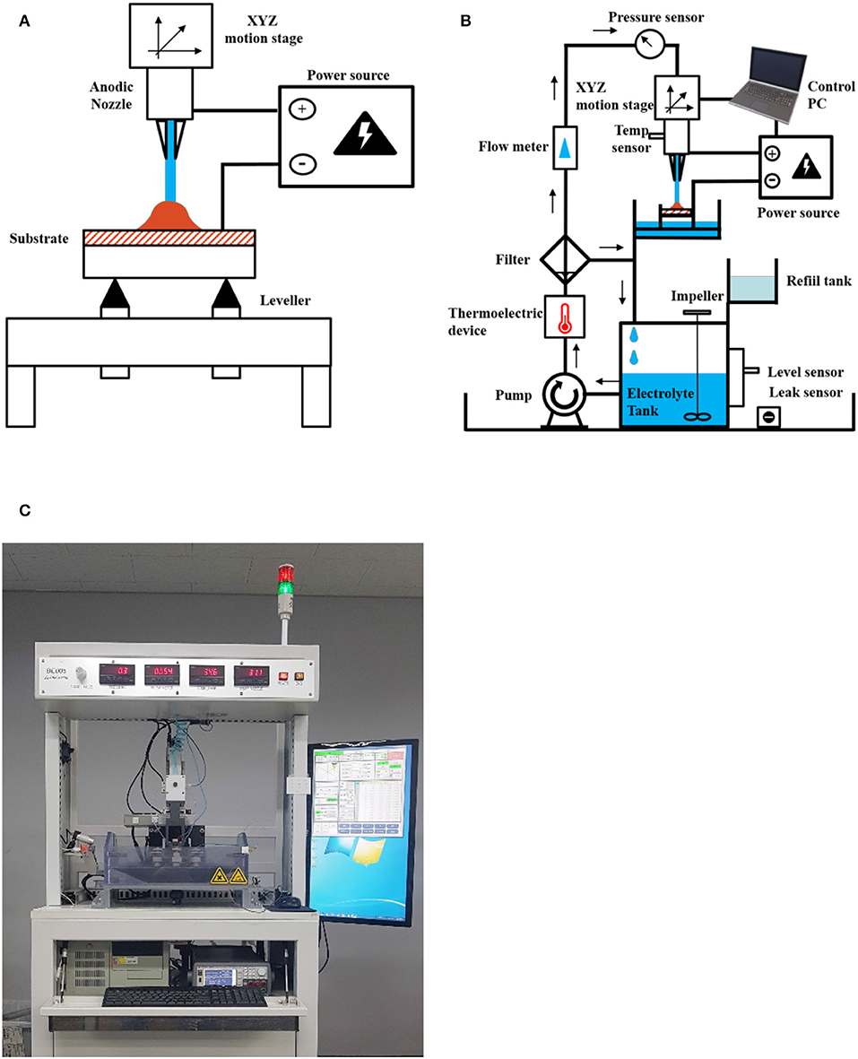
Figure 1. Schematic diagram of the electroplating system, in which the small letters denote the following: (A) concept of 3D printing by the electrochemical method with an electrolyte jet; (B) experimental setup; (C) photo of the actual experimental configurations.
The nozzle section is designated as an anode and it can move through three dimensions (XYZ) with computational control. A cathode is connected to the substrate on which the electrodeposition of the product occurs. A leveling device is installed to maintain a horizontal substrate level.
The composition and properties of the electrolyte for 3D printing are shown in Table 1.
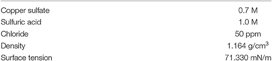
Table 1. Electroplating bath compositions and physical characteristics.
In this experiment, the electrochemical and nozzle fluid dynamics were employed for the additive process, which was carried out as shown in Table 1. The Cu electrolyte solution was selected for the 3D printing because the electrodeposition of Cu exhibited almost 100% cathodic efficiency. The solution in the electrolyte tank supplied by the magnetic pump was jetted through a nozzle at a constant flow pressure. In addition, the solution in the electrolyte tank was mixed using an impeller mixer during the deposition process to make the solution homogeneous. The anode was connected to the nozzle and the cathode was connected to the substrate to apply a constant current. Subsequently, the nozzle was moved at a speed of 500 μm/s using a linear stepping motor. The products were observed using a 3D optical microscope. (RH-8800, HYROX Co.).
Results and Discussion
Different sizes of Cu pillars were formed by the 3D electrochemical deposition system, which was introduced in the experimental section with different temperatures. From previous research, it was demonstrated that an increase in temperature can enhance the electrical conductivity as well as the solubility of metal salt, which is a positive factor that increases the deposition rate (Matula, 1979; Hayashi, 2004). Therefore, the rate of the pillar formation was expected to increase. However, as is shown in Figure 2A, the deposition rate decreased as the temperature increased, which was contrary to expectations. Such contradictory results are owing to the different latency times at different temperatures for the formation of the initial convex structure, as shown at Figure 2B, which is required to initiate the growth of the pillars. The initial convex structure is very critical to the 3D structure formation because the reduction in current would be concentrated at the top of this convex structure, which would provide a selectively rapid growth rate and promote the directional growth of the pillar. Figure 2C clearly shows the initial area of Cu deposits before the formation of the convex structure at 55°C, which is significantly larger (area = ~2.58 mm2) than that at 25°C (diameter = ~1.82 mm2). At relatively high temperatures, the movement of water molecules by convection becomes significant and the overpotential at the interphase decreases; therefore, the current concentration, which is essential for establishing the 3D structure, is hindered by increasing the temperature. Figure 2D represents the shape of the Cu pillars obtained at different temperatures. As shown in the figures, a relatively long Cu pillar is obtained at 25°C, which delivers the fastest deposition rate. At 55°C, the total length of the Cu pillar is relatively low, and the surface is very rough. Such roughness could be owing to the occurrence of unspecific oxidation during the deposition by the dissolved oxygen in the electrolytes at relatively high temperatures.
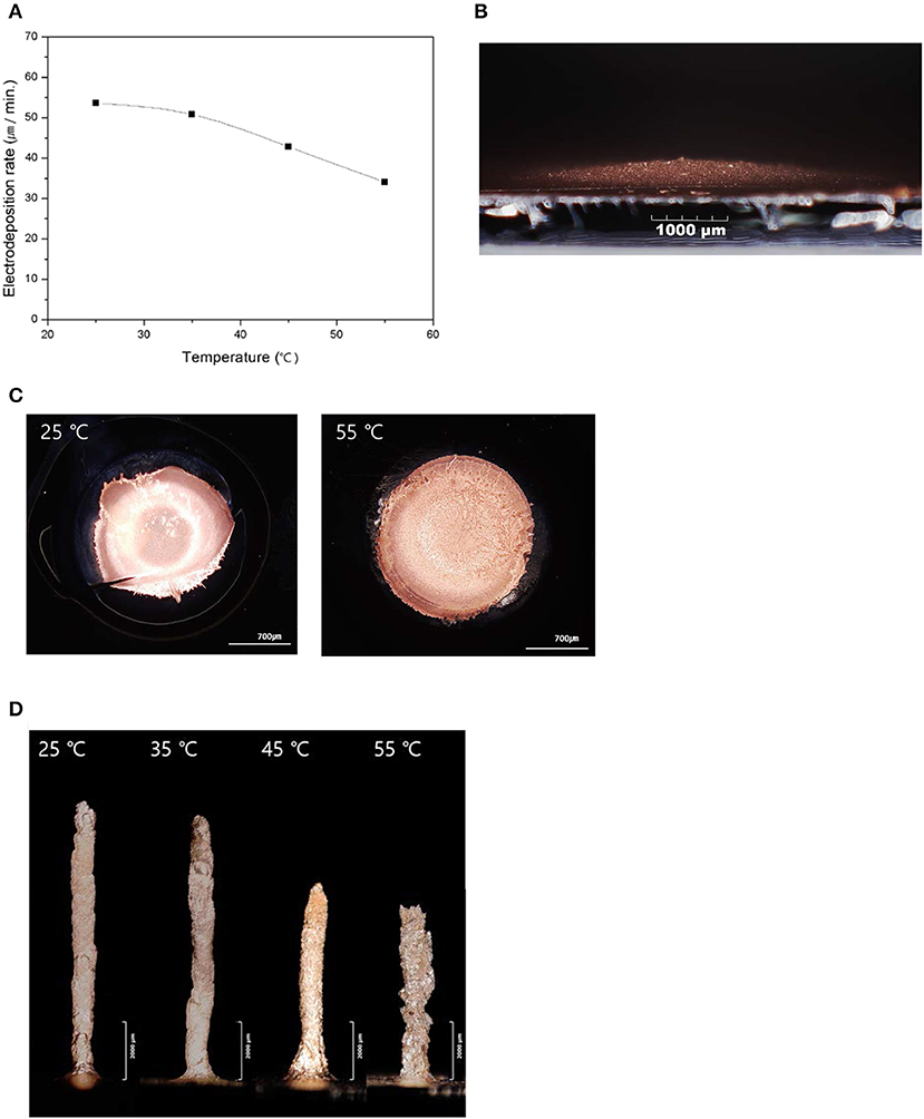
Figure 2. Electroplating characteristics according to the electrolyte temperature, in which the small letters denote the following: (A) electrodeposition rate depending on the electrolyte temperature; (B) initial convex shape of deposition of Cu; (C) shape of the initial Cu deposit structures obtained at different temperatures; (D) directional growth of the pillars depending on the electrolyte temperature.
The effect of applied current on the deposition rate was also investigated. Basically, a relatively high applied current enhances the deposition rate of the electrochemical deposition process (Golden et al., 1996; Bohannan et al., 1999). In our experiments, the deposition rate was also increased by increasing the applied current (Figure 3A). However, when the current was increased, the shape of the Cu pillar became irregular. As the current was sufficiently high, the nucleation of new grains at the top of the pillar, which was the current concentrated position, was enhanced. Therefore, the initiation of new grains became more favorable, compared to the continual growth of existing grains. The emergence of new grains promoted the irregular shape of the pillar when the applied current was high, i.e., I = 25 mA (Figure 3B).
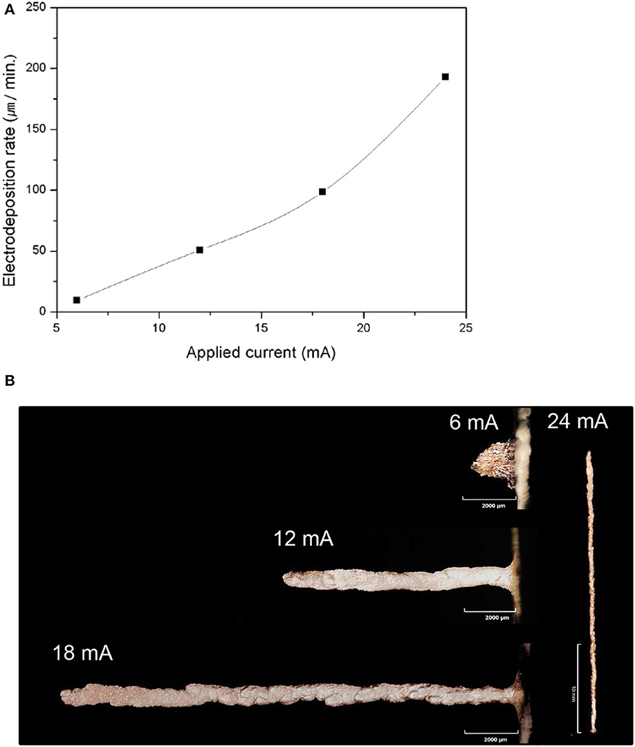
Figure 3. Electroplating characteristics according to the applied current, in which the small letters denote the following: (A) electrodeposition rate depending on the applied current; (B) directional growth of the pillars depending on the applied current.
The effects of the flow pressure, which is the direct parameter for controlling the mass transport of electrolytes during the electrodeposition, on the deposition rate and the shape of the pillar were also investigated. The relatively high flow pressure could increase the transport of metal ions by increasing the convection effect, which would prevent the ion depletion at the growth interface. Figure 4 shows the variation in the deposition rate with the flow pressure. As shown in the graph, when the flow pressure was 5 kPa, the growth rate was ~15 μm/min; however, it was increased and saturated at ~50 μm/min and the shapes of the deposited pillars became increasingly similar as the flow pressure increased over 15 kPa. Evidently, this indicates that the 5 kPa pressure was inadequate to overcome the depletion of ions and the rate of ion transport was saturated when the flow pressure reached 15 kPa.
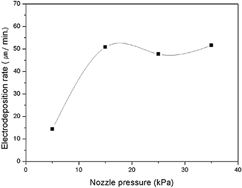
Figure 4. Electrodeposition rate depending on the nozzle pressure.
As the deposition progressed, the height of the Cu pillar changed, which spontaneously changed the distance between the top of the Cu pillar and the nozzle. Such variation in the distance could affect the deposition process. However, the deposition rate was maintained, even though the distance was varied from 5 mm to 35 mm (Figure 5). This was attributed to the constant current flowing between the nozzle and the pillar at any distance.
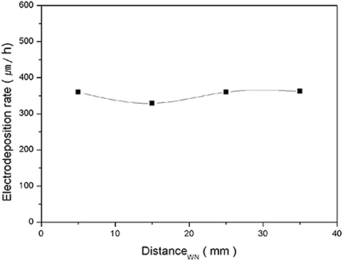
Figure 5. Electrodeposition rate depending on the distance from the working electrode to the nozzle.
Figures 6A,B shows the current variation during the 150-min deposition. When the deposition was performed for 150 min, with an initial distance of 15 mm, the final distance was 6.5 mm owing to the growth of the Cu pillar. During the deposition, the current was maintained as a constant and this evidently confirmed that the applied current was not changed by the distance, at least within this range. However, the responding voltage was decreased from ~12 V to ~8.8 V (Figure 6C), which was owing to the decrease in the electrical resistance as the distance decreased. Although, the deposition rate did not vary with distance, the variation in the responding voltage was not favorable for maintaining the quality of the electrodeposited metal structure because it could cause a change in the microstructure and other physical properties of the deposited materials. Therefore, the movement of the nozzle was automated. If the responding voltage is decreased to more than 1 V, the nozzle is automatically moved upward through 2.7 mm to minimize the variation in the responding voltage. Consequently, as shown in Figure 6D, the responding voltage was maintained within the range of ±1.7 V from the initial voltage.
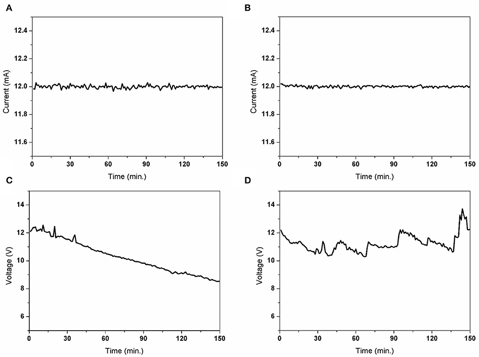
Figure 6. Comparison of the electrical signal (current, voltage) with/without a gap change (distance between the substrate and working electrode) during the stacking of the Cu pillar for 150 min. The small letters denote the following: (A) a nozzle fixed current variation; (B) gap controlled current variation; (C) nozzle fixed voltage variation; (D) gap-controlled voltage variation.
A 3D square wall structure with Cu was successfully constructed through this process (Figure 7A). The size of the square wall was 9 × 9 mm with a height of 1 mm. The applied current was 12 mA, with a nozzle pressure of 15 kPa. Unexpectedly, as shown in Figure 7B, the height at each square corner was slightly higher than at the middle of the wall, which might be owing to the different overlapped sections during the process. Figure 8 demonstrates the increment in the overlapped area at the edge of the square, which was not observed in the case of the circular shape. Therefore, the over-deposition at the corner would be minimized by controlling the moving speed at each corner.
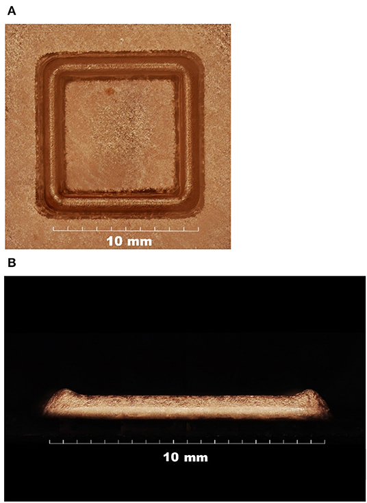
Figure 7. Three-dimensional square wall structure with Cu, in which the small letters denote the following: (A) top view and (B) side view.
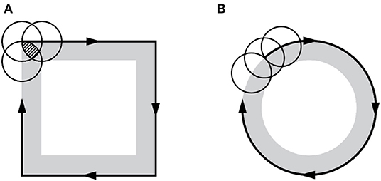
Figure 8. Increment of the overlapped area at the edge of the square, in which the small letters denote the following: (A) overlapped area in square and (B) in circle.
In Figure 9A, Micro coils mostly applied in micromechanical systems(MEMS) device was fabricated using our electrochemical 3D method. the overall structure is 3 × 4 mm, and the line/space is precisely controlled as 4.40/1.25 micrometer. More complicated 3D structure, star-like pattern was also successfully prepared as shown at Figure 9B. The total process time was 400 min for obtained 1,012 micrometer height of star-like structure. Applied current was 2 mA and temperature was maintained at 25°C.
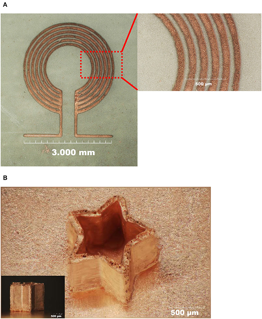
Figure 9. (A) The 2D micro-coils structure and (B) the 3D star-like structure fabricated using electrochemical 3D printing technology.
Conclusions
In this research, a 3D metal additive manufacturing technology with Cu was demonstrated by the electrochemical deposition process through the electrolytic jetting method. The effects of applied current, temperature, jetting pressure and the distance between the nozzle and substrate were studied. The applied current critically affected the growth rate of the Cu deposits, as well as their shapes. The jetting pressure also influenced the growth rate of deposits; however, the effect was saturated above 15 kPa. The distance was not a very critical deciding factor in the deposition; conversely, the scanning rate was precisely controlled to obtain a uniform 3D structure.
Data Availability Statement
The datasets generated for this study are available on request to the corresponding author.
Author Contributions
YK is the first author of this work and he performed most of experiments. DK especially contributed to do the experiment for conforming the effect of temperature and working distance. HK is the main engineer who build up the machine which was utilized in these experiments. SK is the director of this work and verified all of data. BY is the main organizer and advisor of this work. Also, he provided the main idea of this work.
Funding
This work was supported by the Korea Evaluation Institute of Industrial Technology grant funded by the Ministry of Trade and Industry (No. 2019-10077278, Development of Metal Additive Manufacturing Machine using Electrochemical Deposition and Nozzle Fluid Dynamics).
Conflict of Interest
YK, HK, and SK were employed by the company Anycasting.
The remaining authors declare that the research was conducted in the absence of any commercial or financial relationships that could be construed as a potential conflict of interest.
References
Ahn, S. H., Lee, H. J., and Kim, G. H. (2011). Polycaprolactone scaffolds fabricated with an advanced electrohydrodynamic direct-printing method for bone tissue regeneration. Biomacromolecules 12, 4256–4263. doi: 10.1021/bm201126j
Bhaduri, D., Penchev, P., Batal, A., Dimov, S., Soo, S. L., Sten, S., et al. (2017). Laser polishing of 3D printed mesoscale components. Appl. Surf. Sci. 405, 29–46. doi: 10.1016/j.apsusc.2017.01.211
Bohannan, E. W., Huang, L. Y., Miller, F. S., Shumsky, M. G., and Switzer, J. A. (1999). In situ electrochemical quartz crystal microbalance study of potential oscillations during the electodeposition of Cu/Cu2O layered nanostructures. Langmuir 15, 813–818. doi: 10.1021/la980825a
Branner, G. (2010). Modellierung Transienter Effekte in der Struktursimulation von Schichtbauverfahren. (Ph.D. thesis). Munich, Germany: Herbert Utz ISBN: 9783831640713.
Conner, B. P., Manogharan, G. P., Martof, A. N., Rodomsky, L. M., Rodomsky, C. M., Jordan, D. C., et al. (2014). Making sense of 3-D printing: creating a map of additive manufacturing products and services. Addit. Manuf. 1, 64–76. doi: 10.1016/j.addma.2014.08.005
Fierz, F. C., Beckmann, F., Huser, M., Irsen, S. H., Leukers, B., Witte, F., et al. (2008). The morphology of anisotropic 3D-printed hydroxyapatite scaffolds. Biomaterials 29, 3799–3806. doi: 10.1016/j.biomaterials.2008.06.012
Gibson, L. J., and Ashby, M. F. (1997). Cellular Solids: Structure and Properties, 2nd Edn. Cambridge: Cambridge University Press. doi: 10.1017/CBO9781139878326
Golden, T. D., Shumsky, M. G., Zhou, Y., Vanderwerf, R. A., Leeuwen, R. A., and Switzer, J. A. (1996). Electrochemical deposition of copper(I) oxide films. Chem. Mater. 8, 2499–2504. doi: 10.1021/cm9602095
Hayashi, M. (2004). Temperature-electrical conductivity relation of water for environmental monitoring and geophysical data inversion. Environ. Monit. Assess. 96, 119–128. doi: 10.1023/B:EMAS.0000031719.83065.68
Huang, S. H., Liu, P., Mokasdar, A., and Hou, L. (2013). Additive manufacturing and its societal impact: a literature review. Int. J. Adv. Manuf. Technol. 67, 1191–1203. doi: 10.1007/s00170-012-4558-5
Hudák, R., Šarik, M., Dadej, R., Živčák, J., and Harachová, D. (2013). Material and thermal analysis of laser sintered products. Acta Mech. Et Autom. 7, 15–19. doi: 10.2478/ama-2013-0003
Jiang, J., Wang, X., Li, W., Liu, J., Liu, Y., and Zheng, G. (2018). Electrohydrodynamic direct-writing micropatterns with assisted airflow. Micromachines 9:1–8. doi: 10.3390/mi9090456
Kasperovich, G., Haubrich, J., Gussone, J., and Requena, G. (2016). Correlation between porosity and processing parameters in TiAl6V4 produced by selective laser melting. Mater. Des. 105, 160–170. doi: 10.1016/j.matdes.2016.05.070
Kodama, H. (1981). Automatic method for fabricating a three-dimensional plastic model with photo-hardening polymer. Rev. Sci. Instrum. 52, 1770–1773. doi: 10.1063/1.1136492
Koff, W., and Gustafson, P. (2012). 3D Printing and the Future of Manufacturing, Leading Edge Forum. Available online at: http://assets1.csc.com/innovation/downloads/LEF_20123DPrinting.pdf (accessed 30 April, 2019).
Matula, R. A. (1979). Electrical resistivity of copper, gold, palladium, and silver. J. Phys. Chem. Ref. Data. 8, 1147–1298. doi: 10.1063/1.555614
Morsali, S., Daryadel, S., Zhou, Z., Behroozfar, A., Qian, D., and Minary-Jolandan, M. (2017). Multi-physics simulation of metal printing at micro/nanoscale using meniscus-confined electrodeposition: effect of environmental humidity. J. Appl. Phys. 121:024903. doi: 10.1063/1.4973622
Murr, L. E., and Johnson, W. L. (2017). 3D metal droplet printing development and advanced materials additive manufacturing. J. Mater. Res. Technol. 6, 77–89. doi: 10.1016/j.jmrt.2016.11.002
Pequegnat, A., Michael, A., Wang, J., Lian, K., Zhou, Y., and Khan, M. I. (2015). Surface characterizations of laser modified biomedical grade NiTi shape memory alloys. Mater. Sci. Eng. C. 50, 367–378. doi: 10.1016/j.msec.2015.01.085
Rajput, M. S., Pandey, P. M., and Jha, S. (2014a). Experimental investigations into ultrasonic-assisted jet electrodeposition process. J. Eng. Manuf. 228, 682–694. doi: 10.1177/0954405413506198
Rajput, M. S., Pandey, P. M., and Jha, S. (2014b). Fabrication of nano-sized grain micro features using ultrasonic-assisted jet electrodeposition with pulsed current supply. J. Eng. Manuf. 228, 1338–1349. doi: 10.1177/0954405413520142
Research Nester (2018). US 3D printing market to reach US$17.2 billion mark by 2020. Met. Powder Rep. 73:174. doi: 10.1016/j.mprp.2018.03.003
Sadie, J. A., and Subramanian, V. (2014). Three-dimensional inkjet-printed interconnects using functional metallic nanoparticle inks. Adv. Funct. Mater. 24, 6834–6842. doi: 10.1002/adfm.201401312
Shamvedi, D., McCarthy, O., O'Donoghue, E., O'Leary, P., and Raghavendra, R. (2017). “Surface treatment of 3D metal printed microwave components,” in 18th Research Colloquium on Radio Science and Communications for a Smarter World (ResearchGate: Dublin) 8–10.
Tarafder, S., Balla, V. K., Davies, N. M., Bandyopadhyay, A., and Bose, S. (2013). Microwave-sintered 3D printed tricalcium phosphate scaffolds for bone tissue engineering. J. Tissue Eng. Regenerative Med. 7 631–641. doi: 10.1002/term.555
Tomas, K. (2017). An Epiphany of Disruption : Ge Additive Chief Explains How 3d Printing Will Upend Manufacturing. GE Reports. Available online at: https://www.ge.com/reports/epiphany-disruption-ge-additive-chief-explains-3d-printing-will-upend-manufacturing/ (accessed May 08, 2019).
Wei, C., and Dong, J. (2013). Direct fabrication of high-resolution three-dimensional polymeric scaffolds using electrohydrodynamic hot jet plotting. J. Micromech. Microeng. 23:025017. doi: 10.1088/0960-1317/23/2/025017
Keywords: three-dimensional additive printing process, electrochemical, nozzle fluid dynamics, electroplating speed, current overlapped area
Citation: Kim Y, Kang D, Kim H, Kim S and Yoo B (2020) The Characteristics of Selective 3D Metal Additive Process Using Electrochemical Deposition and Nozzle Fluid Dynamics. Front. Mech. Eng. 6:9. doi: 10.3389/fmech.2020.00009
Received: 21 October 2019; Accepted: 18 February 2020;
Published: 03 March 2020.
Edited by:
Bahattin Koc, Sabanci University, TurkeyReviewed by:
Chi Zhou, University at Buffalo, United StatesEric Eisenbraun, SUNY Polytechnic Institute, United States
Copyright © 2020 Kim, Kang, Kim, Kim and Yoo. This is an open-access article distributed under the terms of the Creative Commons Attribution License (CC BY). The use, distribution or reproduction in other forums is permitted, provided the original author(s) and the copyright owner(s) are credited and that the original publication in this journal is cited, in accordance with accepted academic practice. No use, distribution or reproduction is permitted which does not comply with these terms.
*Correspondence: Sung-bin Kim, a3NiQGFueWNhc3RpbmcuY29t; Bongyoung Yoo, Ynl5b29AaGFueWFuZy5hYy5rcg==