 Kyriakos Komvopoulos
- Department of Mechanical Engineering, University of California, Berkeley, Berkeley, CA, United States
The highly complex contact interface phenomena require analysis at different length scales ranging from nanometer up to nearly centimeter scales. When two nominally smooth surfaces are brought into contact, solid-solid interaction across their contact interface is confined at multiple protrusions (asperities) of various shapes and sizes. The deformation mechanisms encountered at the asperity level control the surface conformity, which, in turn, influences the transmission of traction, heat, and electric current across the contact interface. Thus, the multiscale roughness of real surfaces necessitates the advance of methodologies and contact models that bridge the spectrum of relevant length scales. Rough surfaces have been traditionally characterized by statistical parameters, which cannot be uniquely determined because they depend on the sampling interval and the resolution of the measuring device. On the contrary, the scale-invariant parameters employed in fractal geometry provide an unbiased representation of the surface topography. This article provides an appraisal of the multiscale mechanical, thermal, and electrical characteristics of rough contact interfaces demonstrating fractal behavior. Theoretical treatments of elastic, elastic-plastic, and fully plastic deformation, heat conduction, temperature rise, and electrical contact resistance are presented for contact interfaces characterized by fractal geometry, providing a fundamental basis for developing multiscale thermo-electro-mechanics analytical treatments for contacting solid bodies.
Introduction
Interface engineering is an interdisciplinary field devoted to the treatment of complex contact interface interactions encountered at different length scales due to the multiscale nature of the surface topography. Consequently, to study the mechanics, heat transfer, and electrical conduction of contact interface phenomena it is necessary to employ multiscale treatments that bridge the spectrum of relevant length scales. This topical area is of high importance because contact interfaces may exhibit a profound effect on the overall response of components subjected to various mechanical, thermal, and electrical effects. A contact interface is defined as the boundary between two solid bodies brought into contact under load. The deformation behavior at a contact interface may diverge significantly from that of bulk materials due to profound differences between surface and bulk microstructures and associated physical properties. Thus, to investigate the mechanics, heat transfer, and electrical conduction of contact interfaces it is necessary to use a multiscale treatment appropriate for rough surface topographies.
The first contact mechanics study is attributed to Hertz (1882, 1896), who derived an elastic contact theory while investigating the effect of clamping on the optical properties of multiple lenses stacked together. This breakthrough development led to the establishment of the field of contact mechanics, which is concerned with the contact deformation behavior of solids possessing various Euclidean macroscopic configurations. Since the primitive work of Hertz, the elastic-plastic contact deformation of solids of revolution attracted significant research attention, largely due to the recognized importance of contact mechanics in the durability of mechanical systems with contact elements. One of the first studies of quasi-static contact is attributed to Hardy et al. (1971), who studied the deformation of an elastic-perfectly plastic half-space compressed by a rigid sphere. In another early study, Dumas and Baronet (1971) analyzed the indentation of an elastic linear hardening half-space by a rigid cylinder and observed flattening of the contact pressure profile and a greater discrepancy from the Hertzian pressure distribution for the least strain hardening material. In following studies, Follansbee and Sinclair (1984) and Sinclair et al. (1985) examined quasi-static spherical indentation of a hardening material in the fully plastic deformation regime, whereas Hill et al. (1989) used a non-linear elastic power-law hardening model to approximate the deformation behavior of a half-space indented by a rigid sphere in the fully plastic regime.
With the development of advanced numerical methods, such as the finite element method, finite difference method, finite volume method, and boundary element method, and the increase of the computational efficiency, more sophisticated contact mechanics studies were performed in following years. Specifically, Bhargava et al. (1985a,b) developed a finite element model of a cylinder in rolling contact with an elastic-perfectly plastic half-space, wherein the cylinder was modeled by a translating elliptical or modified elliptical pressure distribution. Kulkarni et al. (1990, 1991) examined the three-dimensional (3D) problem of a rigid sphere in frictionless contact with a linear kinematic hardening semi-infinite solid, using a translating Hertzian pressure distribution to simulate the loading by the sphere. Kral et al. (1993) examined cyclic spherical indentation of an elastic-plastic half-space with or without isotropic strain hardening and obtained solutions of the contact response in the first load cycle of fully plastic deformation. Mesarovic and Fleck (1999) presented results of the mean contact pressure and deformation mechanism maps of indented elastic, perfectly-plastic, and elastic-hardening solids. Yan and Li (2003) analyzed contact of an elastic-perfectly plastic half-space with a rigid sphere and reported an increasing trend of the contact pressure distribution to deviate from the Hertzian solution with accumulating loading cycles. Kadin et al. (2006a,b) considered multiple indentation loading and unloading of an elastic-plastic spherical contact for a wide range of material properties. Park and Pharr (2004) and Kogut and Komvopoulos (2004a) provided generalized solutions of the mean contact pressure in terms of a normalized indentation strain parameter for elastic-perfectly plastic materials. A similar concept, specific to dynamic contact, was employed in recent contact mechanics studies dealing with spherical indentation of elastic-plastic half-spaces with and without strain hardening and strain rate-dependent constitutive laws (Lee and Komvopoulos, 2018, 2019). An important finding of the former dynamic contact studies is that general solutions of dimensionless global field parameters, such as the dimensionless mean contact pressure, can be derived in terms of a normalized strain parameter defined as the product of two strains, i.e., the yield strain and the indentation strain.
Despite invaluable insight into the macroscale contact mechanics of Euclidean solids subjected to various loadings provided by the above mentioned studies and many others performed in recent years, real surfaces are not smooth but they comprise geometrical features spanning a wide range of length scales. Therefore, insight into the local deformation behavior at the peaks of surface undulations (asperities) where actual contact occurs necessitates the use of multiscale treatments. Thus, microscale contact theories were advanced to elucidate the evolution of deformation at asperity microcontacts. Archard (1953, 1957) was one of the first researchers to realize that nominally smooth surfaces actually comprise numerous asperities of various sizes on top of each other. Greenwood and Williamson (1966) are credited for the first probabilistic contact model of rough surfaces wherein the asperity heights are assumed to follow a normal distribution. However, the former model is seriously limited by the invariance of the asperity radius and the lateral spacing of the asperities. Consequently, all of the previous contact mechanics analyses based on this model are inadequate.
The topography of real surfaces has been traditionally characterized by statistical parameters of the surface height distribution, such as the root-mean-square roughness and the slope and curvature of the asperities (Greenwood and Williamson, 1966; Nayak, 1973). However, because the topography of real surfaces is a non-stationary process (Sayles and Thomas, 1978), the statistical parameters used to describe the surface morphologies depend on the sample size and the resolution of the imaging instrument and, consequently, cannot be uniquely defined. Therefore, for an accurate surface description, it is necessary to employ approaches based on surface parameters that do not depend on the length scale and the resolution of the imaging device.
Following the observation that the power spectra of most engineering surfaces obey an inverse power law over a wide range of length scales (Majumdar and Tien, 1990), scale-invariant surface characterization methods accounting for the presence of geometrically similar features at different magnifications (self-affinity property) began to attract the research attention, ultimately leading to the implementation of fractal geometry (Mandelbrot, 1983) in the field of contact mechanics. Many natural phenomena, substances, and organs (e.g., cleavage, fracture, clouds, mountains, trees, coastlines, lightning, flames, precipitation, turbulence, film growth, proteins, pulmonary vessels, and heart beating) do not demonstrate shapes described by Euclidean geometry. Fractal geometry offers an effective means of describing, measuring, or even predicting these natural phenomena, studying the response of matter to external stimuli, and characterizing the topography of real surfaces. Indeed, experimental evidence derived from high-resolution microscopy has confirmed that most real surfaces exhibit fractal behavior. The inverse power law followed by the power spectra of most engineering surfaces over a wide range of length scales (Majumdar and Tien, 1990) motivated the introduction of fractal geometry in contact mechanics, ultimately leading to the establishment of a new subfield known as contact mechanics of fractal surfaces, which is concerned with multiscale deformation behavior instigated at contact interfaces demonstrating fractal behavior in a wide range of length scales (e.g., see studies of Majumdar and Tien, 1990; Majumdar and Bhushan, 1991; Wang and Komvopoulos, 1994a,b, 1995; Blackmore and Zhou, 1998a,b; Komvopoulos and Yan, 1998; Yan and Komvopoulos, 1998; Komvopoulos and Ye, 2001; Yang and Komvopoulos, 2005; Song and Komvopoulos, 2014).
From the foregoing discussion, it follows that the multiscale nature of surface roughness complicates the physical phenomena encountered at contact interfaces, such as deformation, heat transfer, and electrical conduction, making the assessment of the performance of thermo-electro-mechanical systems cumbersome. The objective of this article is to present a multiscale theoretical treatment of contact interfaces subjected to mechanical, thermal, and electrical effects and establish correlations between dimensionless quantities that describe the behavior of contact interfaces demonstrating multiscale roughness characterized by fractal geometry.
Multiscale Characterization of Real Surfaces
The most important properties of rough surfaces showing fractal behavior are continuity, non-differentiability, and self-affinity. These mathematical properties are scale-invariant and are satisfied by the so-called Weierstrass–Mandelbrot (W–M) function (Berry and Lewis, 1980), which in its dimensionally consistent two-dimensional (2D) form is given by (Wang and Komvopoulos, 1994a)
where L is the length of the imaged surface profile, G is the fractal roughness, D (1 < D < 2) is the fractal dimension, n is a frequency index, and γ (γ > 1) is a scaling parameter that controls the density of frequencies in the profile and the self-affine property. The right hand side of Equation (1) is a superposition of cosine functions of geometrically increasing frequency. The frequency index n assumes values between zero and nmax = int [log(L/L0)/log γ], where int[…] denotes rounding off of the quantity enclosed within the brackets to its maximum integer and L0 is the smallest wavelength in the surface profile. For continuum description to hold, L0 is typically set equal to 5–6 times the lattice distance of the material. The value of γ is chosen to yield phase randomization and a high spectral density. Surface flatness and frequency distribution density considerations suggest that a reasonable choice is γ = 1.5 (Yan and Komvopoulos, 1998). The scaling parameter γ plays another important role in the fractal description. Specifically, if the lateral length x is magnified by γ, then the height z is magnified by γ(2−D), i.e., z(γx) = γ(2−D)z(x) (Berry and Lewis, 1980). The former is the self-affinity relation that characterizes self-affine fractals and is attributed to fundamental physical laws that are independent of length scale within certain geometrical ranges (Le Mehaute, 1991).
The power spectrum function of a fractal surface profile is the Fourier transform of the autocorrelation function of z(x) and is given by (Majumdar and Tien, 1990; Yang and Komvopoulos, 2005),
where ωc is the spatial frequency, which is related to the circular frequency ω by ωc = 2πω.
When two fractal surfaces with height functions z1(x) and z2(x) are brought into contact, a bifractal contact interface is formed whose power spectrum is the sum of the power spectra and of surfaces (1) and (2), respectively. This relation holds because any two fractal surfaces are statistically uncorrelated. Since and generally intersect at a frequency , it may be inferred that can be approximated by either or , depending on the dominant power spectrum in the ranges and (Yang and Komvopoulos, 2005). Consequently, the equivalent topography of a two-surface system can be represented by a single set of fractal parameters, i.e., those of the surface with the dominant power spectrum in the particular frequency (wavelength) range.
To account for dimensionally higher stochastic processes, the W–M function can be generalized by introducing multiple variables. In this generalization, the homogeneity and scaling properties of the single-variable function given by Equation (1) are preserved and the self-affine property still holds. Thus, a two-variable function can be used to model 3D fractal surfaces exhibiting undulated morphologies in all directions. The height function of a 3D fractal surface demonstrating randomness in all planar directions can be obtained as the real part of the function given by (Ausloos and Berman, 1985)
where ρ and θ are the planar polar coordinates of a surface point of height z and are related to the planar Cartesian coordinates x and y by and θ = tan−1(y/x), γ and n have the same physical meaning and magnitudes as in Equation (1), Am is a parameter controlling the anisotropy of the surface topography (for isotropic surfaces Am = A regardless of the value of m, whereas for anisotropic surfaces Am is a function of m), D (2 < D < 3) is the fractal dimension of the 3D surface profile, ϕm,n is a random phase uniformly distributed in the interval [0, 2π] by a random number generator and is used to prevent the coincidence of different frequencies at any point of the surface profile, k is a wavenumber related to the sample size (k = 2π/L), αm is an arbitrary angle used to offset the ridges in the azimuthal direction (for equally offset ridges αm = πm/M), and M is the number of superposed ridges used to construct the surface topography. The appropriate value of M can be determined from the power spectrum of the imaged surface morphology. For example, for a 2D surface with cylindrical corrugations M = 1, whereas for an isotropic 3D fractal surface characterized by an axially symmetric power spectrum M ≥ 4 (Komvopoulos and Yan, 1998; Yan and Komvopoulos, 1998).
The surface height function z(x, y) of a 3D isotropic surface (Am = A) can be obtained from Equation (3) by introducing a length parameter G that satisfies the relation A = 2π(2π/G)2−D and substituting the above relations of αm, ρ, θ, and k, and the limits of n into Equation (3) (Yan and Komvopoulos, 1998), i.e.,
Figures 1A,B show 3D fractal surfaces generated with Equation (4) for G = 9.46 × 10⁻⁴ nm and D = 2.3 and 2.6, respectively, and all other parameters fixed. Considering the different scales in the z-direction of the plots, although the surface shown in Figure 1B is smoother than that shown in Figure 1A, at a smaller scale (higher magnification) it appears to be of similar roughness. Another important difference of the two surface morphologies that elucidates the physical meaning of the fractal dimension is that the surface topography with D = 2.6 is dominated by higher frequency components, whereas the surface topography with D = 2.3 is characterized by a greater contribution of lower frequency components.
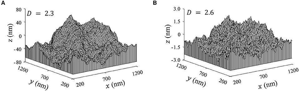
Figure 1. Fractal surfaces generated from Equation (4) with G = 9.46 × 10⁻⁴ nm and (A) D = 2.3 and (B) D = 2.6.
An interesting difference between classical geometry and fractal geometry is that while the former uses integer dimensions (i.e., 0 for points, 1 for lines and curves, 2 for planes, and 3 for 3D geometries), a dimension in fractal geometry varies between two integer numbers. For example, although a straight segment has a dimension of 1, a surface consisting of many interconnected segments can have a dimension between 1 and 2 (1 < D < 2) for 2D surfaces or between 2 and 3 (2 < D < 3) for 3D surfaces, depending on the space-filling capacity of the surface profile. Thus, a surface containing a very large number of tiny hills and valleys residing on a tall hill would be close to the second dimension, whereas a nominally flat surface profile with a very large number of hills and valleys would be close to the third dimension. Therefore, the amplitude ratios of high-to-low frequency (short-to-long wavelength) components increase with D and the surface topography appears rougher when the vertical scale is comparable to the amplitude of the lowest frequency component, as shown in Figure 1B. This illustrates the physical significance of the fractal dimension. With regard to the physical meaning of the fractal roughness, Equations (1, 4) show that G controls the amplitude of the frequency components comprising the surface profile. Equations (1, 4) also indicate that the fractal roughness is a height scaling parameter independent of frequency. Thus, the 2D and 3D functions given by Equations (1, 4) can be used to generate randomized rough surface profiles because the only unknown parameters are the scale-independent parameters D and G that can be found experimentally. Therefore, fractal description is not limited by the resolution of the imaging instrument and/or length scale of measurements due to the intrinsic capability of fractal geometry to represent surfaces at various length scales, even different from those of the measurements. Consequently, a fractal surface can be characterized by three uniquely defined parameters, i.e., D, G, and L.
The frequency (or wavelength) range where fractal behavior is observed can be determined as the range where the power spectrum of the surface profile is an inverse power function of frequency [Equation (2)]. In general, the range of length scales where an engineering surface demonstrates fractal behavior depends on the architecture of the topography. This is because the processes used to produce the final surface may contribute differently to the resulting surface morphology. For example, although polishing is a random process at length scales equal to or less than the average grit size, at larger scales its effect can be described by a deterministic process, such as in the case of wafer planarization, for example. Consequently, although a fractal description may be applicable at the micro/nanoscale, the macro/mesoscale configuration of the majority of engineering surfaces is described by Euclidean geometry. Nonetheless, if the macroscopic shape of surfaces is also produced by a random process (e.g., lithographically fabricated thin-film devices), a fractal surface description at the macroscale is also plausible. In the foregoing case, the above fractal surface theory is applicable provided the fractal parameters determined for each range of length scales are used in the analysis. In these circumstances, a unique set of fractal parameters cannot be used throughout the range of length scales where fractal behavior is observed and the surface is said to exhibit multi-fractal behavior. Moreover, if fractal behavior is limited to a certain range of length scales and the geometrical shape above this scale is deterministic, that is, the topography comprises both fractals and regular shapes, the surface is referred to as fractal-regular (Wang and Komvopoulos, 1994b) and fractal description holds up to a finite length Lu, termed the upper limit of sample length for fractal characterization, which can be determined from the power spectral density function of the surface topography. For instance, Lu can be obtained as the wavelength corresponding to the spatial frequency at which the spectral density function begins to deviate from the fractal power-law behavior [e.g., Equation (2)]. Thus, for fractal characterization to be applicable, the fractal sample length L in Equations (1, 4) must be less than or equal to Lu.
Multiscale Contact Mechanics
The mechanical characteristics of contact interfaces are a manifestation of multiple asperity deformation encounters instigated by the multiscale nature of the surface roughness (Figure 2A). Consequently, the mechanics of contact interfaces require the integration of contact deformation at the asperity level with multiscale surface description. The contact interface of two fractal surfaces can be modeled by Equations (1, 3, 4) using the fractal parameters of the dominant power surface spectrum in the frequency (wavelength) range of interest or a multi-fractal description as stated in the previous section. Thus, the problem can be simplified to that of a deformable fractal surface in contact with a rigid flat plane at a global surface interference d, resulting in the formation of multiple asperity microcontacts of various sizes (scale effect), as shown in Figure 2B. Each truncated asperity is modeled as a sphere with its truncation by a local surface interference distance δ yielding a circular truncated contact area of radius r′, as shown in Figure 2C. Therefore, a contact mechanics analysis of the interface requires knowledge of the distribution of asperity microcontacts at a given global surface interference and the deformation behavior at the asperity scale.
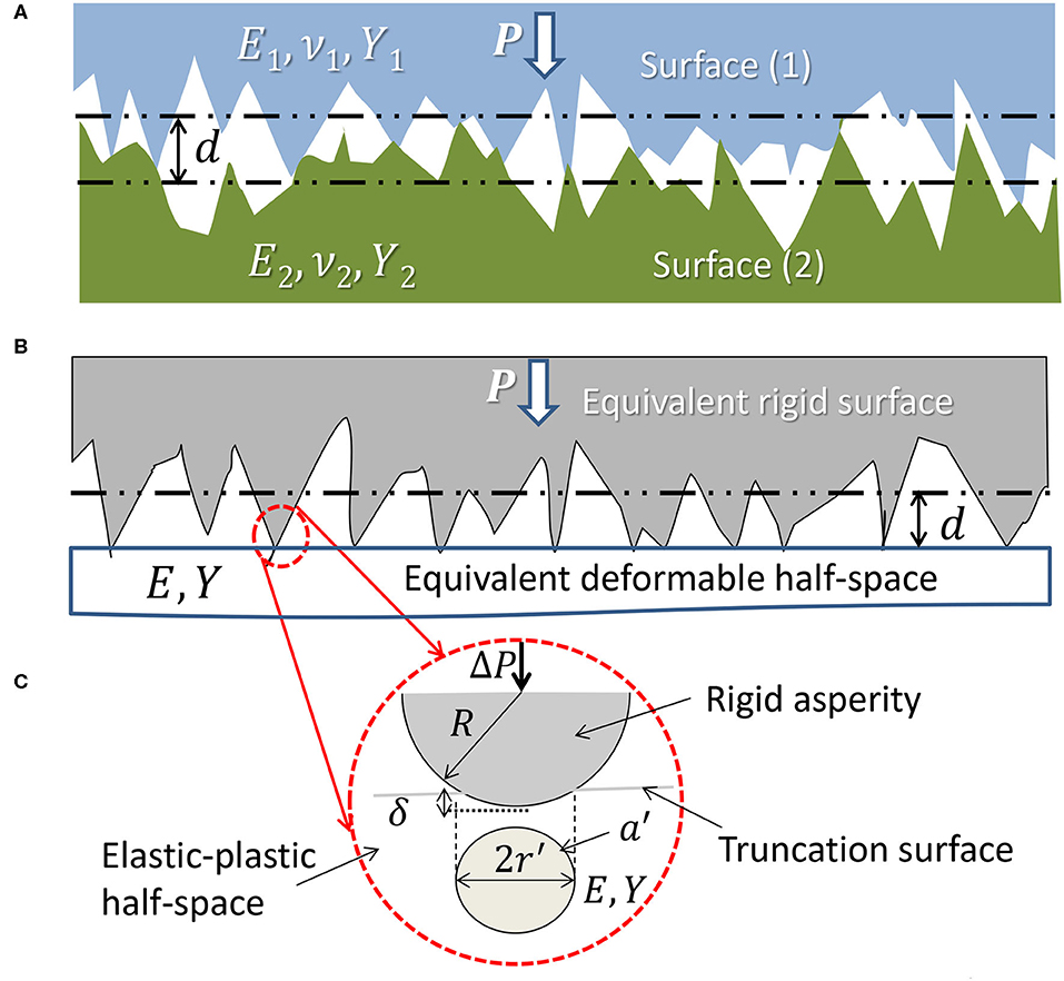
Figure 2. (A) Contact of two rough surfaces confined at asperity microcontacts, (B) equivalent contact configuration of a deformable half-space with effective elastic-plastic material properties and an equivalent rigid and rough surface with fractal parameters those of the dominant surface power spectrum in the frequency range of interest, and (C) model of an asperity microcontact consisting of a rigid spherical asperity truncated by an elastic-plastic half-space.
An example of a fractal surface truncated by a rigid plane is shown in Figure 3. For a relatively small global surface interference, contact is confined to a few scattered microcontacts of various sizes (Figure 3A). With increasing global surface interference, more microcontacts form and some of the previously established microcontacts enlarge by merging with neighboring microcontacts (Figure 3B). Figure 4 shows an analogous model of asperity microcontacts, approximated by circular spots, forming at the contact interface of two rough surfaces brought together under a normal load P. Thus, the real contact area A, i.e., the sum of all the microcontact spots, is much smaller than the apparent contact area Aa. If the contact model shown in Figure 2B is simplified to that shown in Figure 4, the truncated areas of the resulting asperity microcontacts can be described by a power-law relation given by (Mandelbrot, 1983)
where N(a′) denotes the number of asperities with truncated contact areas greater than a′, and is the largest truncated microcontact area. Using Equation (5), the distribution function of truncated asperity microcontact areas can be expressed as (Yan and Komvopoulos, 1998)
where can be determined from the measured truncated contact area A′ of the surface profile using the relation,
where is the smallest truncated microcontact area, which represents the cut-off contact area below which a continuum mechanics description cannot be applied. Since , Equation (7) can be simplified to the following
The total area of the truncated asperity microcontacts A′ can be determined from the fractal surface height profile [Equation (4)] by summing all the pixels with z-heights greater than the height of the truncation plane. Accordingly, and n(a′) can be obtained from Equation (7, 8) and Equation (6), respectively. Therefore, the spatial distribution of the truncated asperities of a given surface profile can be fully determined. However, because depends on the global surface interference d (or contact load P) through A′, the contact behavior can be very inconsistent. After the truncation of the rough surface by the rigid plane to a certain global surface interference and the establishment of the area distribution of truncated asperity microcontacts [Equation (6)], the deformation mode of each microcontact must be examined. This necessitates the implementation of contact deformation equations at the asperity level.
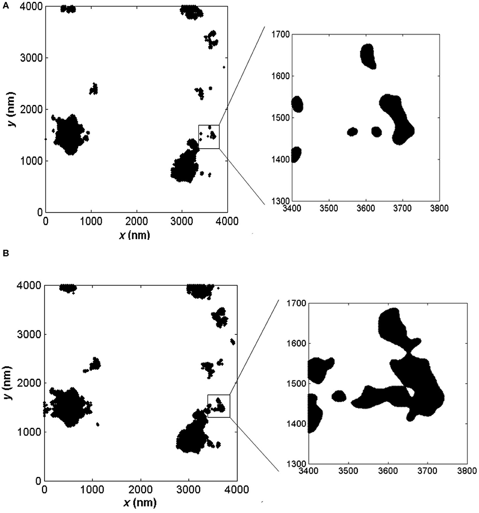
Figure 3. Plane views of a truncated fractal surface. (A) At a given global surface interference, the truncated microcontact areas resemble islands of various sizes. (B) At a larger global surface interference, new microcontacts form and some merge with existing microcontacts to form larger microcontact areas.
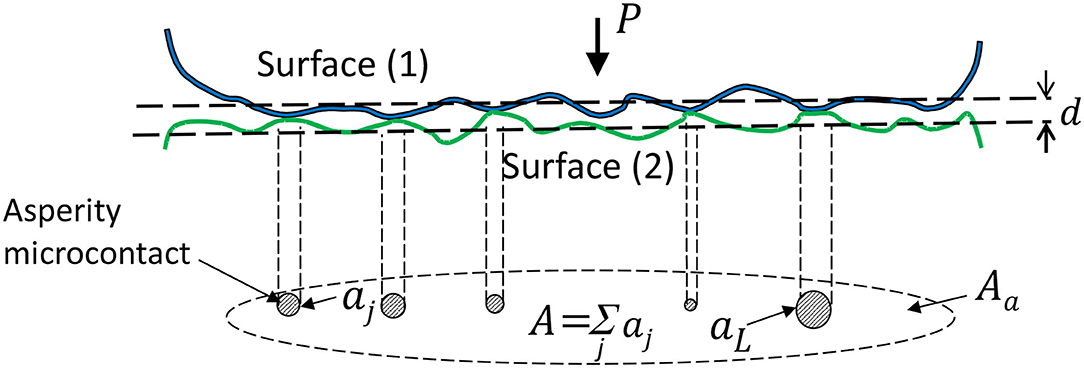
Figure 4. A model of two rough surfaces under load showing that actual contact occurs at asperity microcontacts of various sizes.
The deformation of spherical (point) and cylindrical (line) contacts has been the focus of numerous 3D and 2D studies, respectively. The common 3D approach has been to represent an asperity microcontact at the contact interface of two deformable surfaces, denoted by (1) and (2) in Figure 2A, by two spheres of radius of curvature R1 and R2, elastic modulus E1 and E2, Poisson's ratio ν1 and ν2, and yield strength Y1 and Y2, respectively, and simplify the analysis by considering the equivalent normal contact problem of a spherical asperity with an effective radius of curvature , effective elastic modulus , and yield strength Y = min[Y1, Y2] truncated by a rigid plane to a local surface interference δ, resulting in the formation of a circular truncated contact area a′ of radius r′, as shown in Figure 2C.
The dimensionless local surface interference δ/r′ and asperity radius of curvature R/r′ are given by (Yan and Komvopoulos, 1998)
Various deformation modes may occur at the asperity level depending on the effective elastic-plastic material properties E and Y and the magnitudes of δ/r′ and R/r′, which are functions of D and G [Equations (9, 10)]. The contact behavior of asperity microcontacts can be simply characterized by elastic and fully plastic deformation (Johnson, 1985; Majumdar and Bhushan, 1991; Komvopoulos and Yan, 1998; Yan and Komvopoulos, 1998), more realistically by elastic, elastic-plastic, and fully plastic deformation (Wang and Komvopoulos, 1994b; Komvopoulos and Ye, 2001; Kogut and Komvopoulos, 2004a), and more precisely by elastic, linear elastic-plastic, non-linear elastic-plastic, transient fully plastic, and steady-state fully plastic deformation (Song and Komvopoulos, 2013). Relations of the dimensionless mean contact pressure and real contact area at the asperity level are given below for the simpler case of three deformation modes, i.e., elastic, elastic-plastic, and fully plastic deformation without strain hardening.
The deformation mode of an asperity microcontact is controlled by the local surface interference δ and the effective elastic-plastic material properties E and Y (Figure 2C). It has been shown that a single dimensionless parameter, such as Eδ/Yr′, does not effectively capture the evolution of deformation in the elastic-plastic deformation regime; therefore, it is preferred to treat the ratios E/Y and δ/r′ as independent dimensionless parameters (Kogut and Komvopoulos, 2004a). Hence, the local contact parameters, such as the dimensionless mean contact pressure pm/Y and the truncated-to-real contact area ratio a′/a, must be interpreted for a wide range of E/Y and δ/r′. Figures 5 and 6 show finite element simulation results revealing the variation of pm/Y and corresponding a′/a with δ/r′, respectively, in the elastic-plastic deformation regime for E/Y in the range of 11–450. All of the simulation cases show that yielding is instigated at pm/Y = 1.07, which, according to Hertz theory, implies elastic deformation in the dimensionless local surface interference range . By curve fitting the maximum values of pm/Y, the critical local surface interference at the initiation of fully plastic deformation is found to be δ/r′ = 1/[1 + 0.037(E/Y)]. For a very small yield strain (e.g., E/Y = 450), pm/Y increases to a maximum of ~2.85, which is close to the similarity solution pm/Y = 3 (Hill et al., 1989; Biwa and Storåkers, 1995), whereas a′/a decreases to a minimum of ~1 as δ/r′ approaches 0.1. Alternatively, for a relatively large yield strain (e.g., E/Y = 11), pm/Y reaches a much lower maximum of ~2.1 for a significantly larger δ/r′ value of ~0.8.
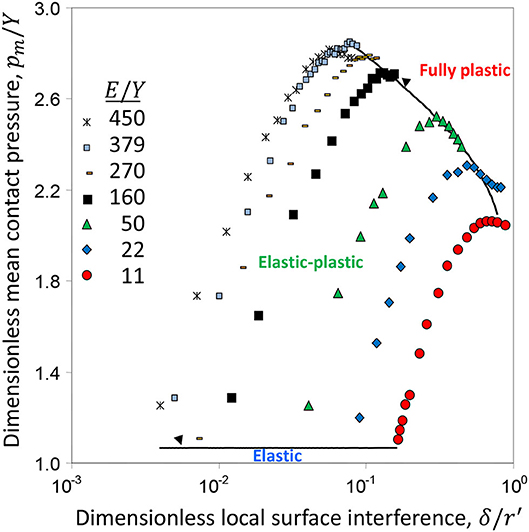
Figure 5. Dimensionless mean contact pressure pm/Y vs. dimensionless local surface interference δ/r′ and effective elastic modulus-to-yield strength ratio E/Y (Kogut and Komvopoulos, 2004a).
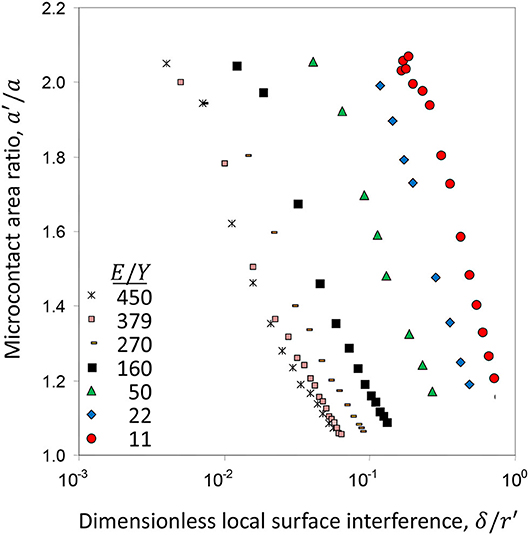
Figure 6. Truncated-to-real contact area ratio a′/a vs. dimensionless local surface interference δ/r′ and effective elastic modulus-to-yield strength ratio E/Y (Kogut and Komvopoulos, 2004a).
From curve fitting the data shown in Figures 5 and 6, the following contact relations for elastic, elastic-plastic, and fully plastic deformation can be obtained (Kogut and Komvopoulos, 2004a).
For elastic deformation (δ/r′ < 1.78/(E/Y)),
For elastic-plastic deformation (1.78/(E/Y) ≤ δ/r′ < 1/[1 + 0.037(E/Y)]),
For fully plastic deformation (δ/r′ > 1/[1 + 0.037(E/Y) ]),
Equation (15) indicates that fully plastic deformation is reached when the dimensionless mean contact pressure reaches a maximum, which (by definition) is the material hardness H = min[H1, H2], where H1 and H2 denote the hardness of contacting surfaces (1) and (2), respectively. For a rigid spherical indenter and rigid-perfectly plastic half-space, the similarity solution gives H = 3Y (Hill et al., 1989; Biwa and Storåkers, 1995). However, Equation (15) shows a significant deviation from the similarity solution with increasing E/Y (i.e., decreasing yield strain Y/E), implying a marked effect of elastic deformation on material hardness. Equation (16) shows that the real contact area reaches a maximum equal to the truncated contact area, in agreement with the slip-line plasticity theory of rigid-perfectly plastic deformation behavior.
By substituting Equation (9) into the critical local surface interference at yielding, δ/r′ = 1.07 , and fully plastic deformation, δ/r′ = 1/[1 + 0.037(E/Y)], the truncated microcontact areas and demarcating the boundaries between elastic and elastic-plastic deformation and between elastic-plastic and fully plastic deformation, respectively, are obtained as
Substitution of Equations (9, 18) into Equation (14) gives
Equations (17, 18) indicate that and are functions of the fractal parameters and elastic-plastic material properties. Accordingly, the deformation mode at asperity microcontacts can be determined from their truncation areas to be elastic , elastic-plastic , or fully plastic .
Defining the dimensionless load applied to an asperity microcontact by and using Equations (9, 11–13, 15–19), the following relations of the dimensionless contact load carried by an asperity microcontact can be obtained for elastic, elastic-plastic, and fully plastic deformation.
For elastic deformation ,
For elastic-plastic deformation ,
For fully plastic deformation ,
The dimensionless (total) contact load and real contact area can be obtained from Equations (20–22) and Equations (12, 16, 19), respectively, by numerical integration, i.e.,
where is the total number of truncated asperity microcontacts with areas greater than the cut-off microcontact area .
In general, for fixed fractal roughness G, both the contact load and real contact area increase with the fractal dimension D. This is because fractal surfaces characterized by high D values demonstrate relatively smooth (dense) surface topographies, which, therefore, demonstrate a higher load-bearing capacity due to the resulting larger real contact area. A similar trend of the contact load and real contact area is observed with decreasing fractal roughness and fixed fractal dimension. This is due to the fact that high G values characterize relatively rough (less dense) surface profiles, signifying a lower load-carrying capacity due to the resulting smaller real contact area.
The foregoing theoretical treatment yields insight into topography and material parameters affecting the evolution of the real contact area at rough contact interfaces exhibiting multiscale (fractal) topographies and has direct implications in experimental methods used to estimate the real contact area that are limited by the sampling length and resolution-dependence of the measuring device. Particularly, the above contact analysis can be used to evaluate real contact area measurements obtained with various experimental methods, including optical (Maegawa et al., 2015), interferometric (Bhushan and Dugger, 1990; Eguchi et al., 2009), electrical (Kogut and Komvopoulos, 2003, 2004b, 2005; Lumbantobing et al., 2004; Sick and Ostermeyer, 2007), and X-ray and electron computed tomography (Yan et al., 2020; Zhang et al., 2020) techniques. The above contact mechanics analysis can also be used to assess the capability of other contact theories and models to reliably analyze the mechanical behavior of contacting rough surfaces, such as those proposed by Archard (1953, 1957), Greenwood and Williamson (1966), Ciavarella et al. (2000), Ciavarella and Demelio (2001), Persson (2001), and Persson et al. (2002). Furthermore, the contact mechanics theory described herein can be extended to include the deformation effect of neighboring asperities, encountered at relatively high loads where plasticity is the dominant mode of deformation, by implementing a more comprehensive theoretical treatment, for example, such as that employed in a recent contact plasticity theory (Wang et al., 2018).
Multiscale Contact Thermomechanics
Even though the transfer of energy in solids has been studied both experimentally and theoretically for many years, relatively fewer studies have been carried out for the energy transferred between contacting solids, presumably because of the difficulties to access the hindered contact interfaces and the fast, localized, and scale depended thermal phenomena instigated by the multiscale roughness. The resistance to transfer heat through contact interfaces has been recognized for a long time and its inconsistency has been attributed to the effects of surface topography, applied contact pressure, and thermomechanical properties of the contacting solids. Thus, the restriction of heat transfer across a contact interface, known as the thermal contact resistance, Rth, is a multiscale thermomechanical phenomenon encountered in many components comprising dynamic contact elements, such as microswitches, gears, bearings, and guideways. As shown in Figure 4, the multiscale nature of roughness at the contact interface leads to A ≪ Aa. Thus, heat conduction across a contact interface is restricted to asperity microcontact spots having a size distribution depending on the fractal parameters that characterize the morphology of the contact interface and the elastic-plastic properties of the interacting solid surfaces. Consequently, a heat transfer analysis of fractal contact interfaces requires a multiscale thermomechanical approach because the deformation and heat conduction at the asperity level are coupled.
The thermal contact resistance depends on the mechanical and thermophysical properties of the contacting bodies, the contact interface morphology, and any interstitial substance (solid or liquid film) that may exist between the surfaces. Considering a vacuum environment (i.e., no heat convection) and that radiation between conductive surfaces is negligible compared to heat conduction, the thermal contact resistance can be analyzed in terms of the heat conducted through the asperity microcontacts. The thermal contact conductance hc is defined as
where Q is the total heat flux and ΔTc = T1 − T2 (T1 > T2), where T1 and T2 are the nominal temperatures of contacting surfaces (1) and (2), respectively. For two contacting spheres (or spherical asperities) with temperatures T1 and T2, the heat flux Q through their circular contact area is given by (Cooper et al., 1969)
where k1 and k2 are the thermal conductivities of surfaces (1) and (2), respectively, and ψ is a contact resistance factor approaching 1 for small values of r/R. Equation (26) can be used to compute the fraction of heat flux ΔQ passing through an asperity microcontact of area aj, i.e.,
Because ΔTc is the same at all asperity microcontacts, the dimensionless thermal contact conductance hc is given by
or in dimensionless form
where aj is given in terms of by Equations (12, 16, 19), depending on the mode of deformation, and is the total number of asperity microcontacts for a global surface interference d. Equation (29) indicates that the thermal contact conductivity is a function of the topography (fractal parameters), thermophysical properties of the contacting surfaces, and contact load (or global surface interference).
In addition to restricting the conduction of heat, the surface roughness is responsible for raising the temperature at sliding contact interfaces. A 2D fractal theory of heat conduction at contact interfaces based on the distribution density function of the temperature rise has provided insight into the fractions of the real contact area subjected to various temperature rises and the maximum temperature rise of a fractal domain for slow and fast sliding contact conditions (Wang and Komvopoulos, 1994a,b, 1995). In this paper, a 3D fractal approach is introduced based on the simplifying concept of the dimensionless average temperature rise at an asperity microcontact given by (Rabinowicz, 1995)
or
where μ is the coefficient of friction, υ is the relative sliding velocity at the contact interface, ρ is the density, c is the specific heat capacity, and superscripts s and f imply slow and fast sliding, respectively. Whether slow or fast sliding occurs depends on the Péclet number Pe = υr/2(k2/ρ2c2). For slow sliding [Equation (30)], Pe < 0.5 and the heat is conducted into both surfaces (Figure 7A), whereas for fast sliding [Equation (31)], Pe > 10 and the heat is conducted from the hotter surface to the relatively cooler surface (Figure 7B).
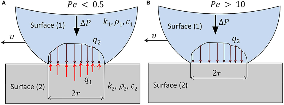
Figure 7. A model of heat conduction at the asperity microcontact level for (A) slow and (B) fast sliding contact conditions.
Substitution of Equations (12, 16, 19–22) into Equations (30, 31) yields the following equations of dimensionless average temperature for elastic, elastic-plastic, and fully plastic asperity microcontacts at the contact interface of relatively slow and fast sliding surfaces, and , respectively.
For elastic asperity microcontacts ,
For elastic-plastic asperity microcontacts ,
For fully plastic asperity microcontacts ,
Equations (32–37) show a dependence of the temperature rise at asperity microcontacts on the thermomechanical properties and fractal parameters of the contacting surfaces, the sliding speed, and the coefficient of friction. They also indicate a stronger dependence of the temperature rise on microcontact area for slow sliding than fast sliding conditions. It is noted that Equations (32–37) are limited to relatively low-friction surfaces, such as lubricated surfaces and low-adhesion (incompatible) solid-solid contact systems (Komvopoulos, 2012) because, in the present treatment, asperity deformation is considered to be due to normal contact loading. However, the present analysis of the frictional temperature rise at the asperity microcontact level can be easily extended to high-friction/high-adhesion contact interfaces by including the effect of the friction force in the contact mechanics analysis presented in the previous section.
To provide quantitative insight into the important effect of the thermomechanical and surface topography properties on the temperature rise at sliding contact interfaces, results of frictional heating for slow sliding (Pe < 0.5) and low friction (μ = 0.15) conditions obtained from a previous 2D thermal analysis of frictional heating at fractal contact interfaces (Wang and Komvopoulos, 1994b) are reproduced in Figure 8. The results are for typical ceramic bearing materials and diamond with thermomechanical properties given in Table 1 and elastic-perfectly plastic material behavior. The higher thermal diffusivity α = k/ρc of diamond is responsible for the larger speed range demonstrated by this material, whereas the higher maximum temperature rise computed for ZrO2 is attributed to its higher effective elastic modulus-to-thermal conductivity ratio E*/k (Table 1). The effect of the fractal parameters D and G* on the fraction of the real contact area of Al2O3-TiC and WC ceramics exposed to temperature rises of ≥69oC due to slow speed sliding can be interpreted in the light of the results shown in Figure 8B. The reason that a larger fraction of the real contact area of the Al2O3-TiC composite ceramic is subjected to temperatures ≥69oC compared to the WC is its higher E*/k ratio (Table 1).
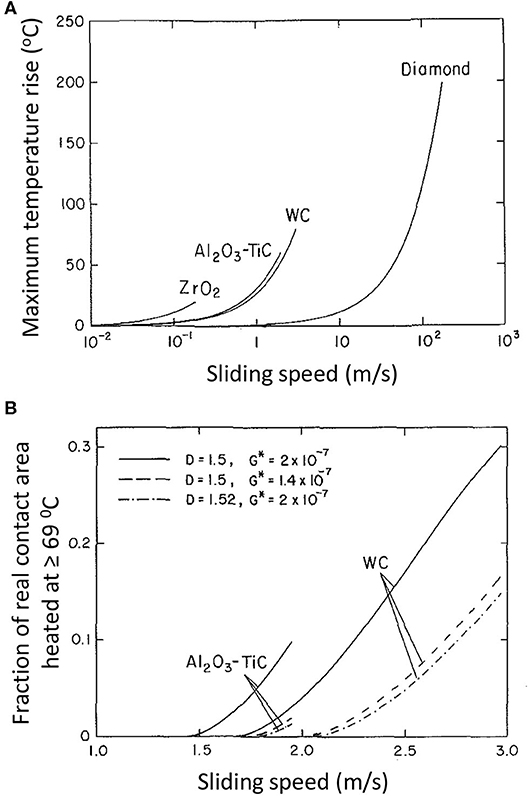
Figure 8. (A) Maximum temperature rise on 2D fractal ceramic and diamond surfaces vs. sliding speed for D = 1.5 and G* = 2 × 10⁻⁷, and (B) effect of fractal parameters D and G* on the fraction of real contact area at a temperature ≥ 69 oC vs. sliding speed for Pe < 0.5 and μ = 0.15 (Wang and Komvopoulos, 1994b).
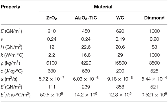
Table 1. Thremomechanical properties of sliding ceramic materials (Wang and Komvopoulos, 1994b).
In general, the temperature rise at asperity microcontacts intensifies with increasing fractal roughness and/or decreasing fractal dimension. The analysis presented in this section reveals a coupling of the topography, mechanics, and thermal aspects of contact interfaces. This is illustrated in the flow chart shown in Figure 9. From the scanned surface topographies, the fractal description of the equivalent surface topography can be obtained and D and G* can be calculated. Subsequently, from the restructured topography [Equation (1) or (4)] and effective mechanical properties E and Y of the contact interface, the dimensionless contact load and contact area of each asperity microcontact can be obtained using the contact equations of the appropriate deformation mode [Equations (5–22)]. Then, the dimensionless contact load [Equation (23)] and contact area [Equation (24)], which are correlated through Equations (11–22), can be obtained by numerical integration. Consequently, the information generated from the contact mechanics analysis together with the thermophysical properties of the contact interface k, ρ, and c, the sliding speed υ, and the coefficient of friction μ can be used to compute the temperature rise using the appropriate temperature equation [Equations (30–37)], depending on the mode of deformation and magnitude of the Péclet number at each asperity microcontact. If the spatial temperature distribution does not meet the application specifications, suitable modifications of the surface topography and thermomechanical properties can be made iteratively using the flow chart shown in Figure 9 until the contact analysis yields a size distribution of asperity microcontacts that produces temperature rises in the desired range for a given contact load, apparent contact area, sliding velocity, and coefficient of friction.
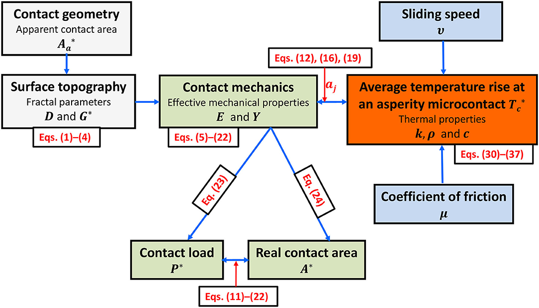
Figure 9. Thermomechanics flow chart for rough (fractal) contact interfaces. Dimensionless parameters are indicated by an asterisk.
In the above thermomechanical contact theory, the effect of heating on the deformation of asperity microcontacts is assumed to be secondary; consequently, the asperity microcontact areas [Equations (12, 16, 19)] used in the temperature rise relations [Equations (30–37)] are determined from the contact mechanics treatment presented in the previous section. The elastic-plastic material properties needed to calculate the asperity microcontact area at the particular temperature rise can be inserted in the appropriate contact mechanics relations after using an iterative procedure. Although this approach couples the thermal analysis with the mechanics analysis, it does not directly account for the effect of temperature on the asperity microcontact size. This can be accomplished by employing a thermomechanical analysis wherein the heat conduction and contact deformation are fully coupled, as demonstrated in other studies (Ye and Komvopoulos, 2003; Gong and Komvopoulos, 2004, 2005).
Multiscale Contact Electromechanics
Similar to the restriction of heat transfer through the contact interface, the multiscale roughness together with a possibly existing insulating surface film, such as a native oxide layer or an adsorbed organic substance, can significantly inhibit the flow of electric current. The restriction of current flux across a contact interface, known as the electrical contact resistance (ECR), is of great importance in many application areas, such as contact-mode microelectromechanical devices, switches, and relays. Holm (1967) was first to observe the evolution of the ECR between two flat electrical conductors pressed into contact. Greenwood (1966) proposed a method for computing the ECR generated by a cluster of microcontacts and showed that it can be regarded as the sum of parallel microcontact resistances. The so-called Holm ECR arises when the size of the contact area is larger than the electron mean free path (Malliaris and Turner, 1971; Schneegans et al., 1998), while the so-called Sharvin resistance (Sharvin, 1965) is encountered when the size of the contact area is smaller than the electron mean free path. Barber (2003) considered elastic contact between two rough conductors and using an analogy between elastic contact and electrical conductance he developed a contact mechanics theory that yields bounding solutions of the electrical conductance. On the basis of the foregoing analogy and Archard's hypothesis, Ciavarella et al. (2004) analyzed the contact conductance of rough surfaces with topographies described by the Weierstrass function. Paggi and Barber (2011) studied the effect of contact pressure on the electrical conductance of rough surfaces exhibiting self-affinity and proposed a power-law relation between the electrical conductance and the mean contact pressure. A general electromechanics theory that uses fractal geometry to describe the surface topography, elastic-plastic deformation at the asperity microcontact level, and size-dependent ECR of microcontacts that includes both the Holm and Sharvin resistances as the asymptotic limits (Mikrajuddin et al., 1999) is presented in this section.
Figure 10A shows two conductive rough surfaces separated by an insulating thin film brought into contact under load P, whereas Figure 10B shows the equivalent contact model consisting of a rigid plane in contact with a deformable rough surface coated with an insulating film of thickness t = t1 + t2, dielectric constant K, and energy height above the Fermi level of the conductive surfaces φ0. The ECR caused by an asperity microcontact comprises the constriction resistance caused by the convergence (or divergence) of the current flow (Holm, 1967) and the tunnel resistance introduced by the thin insulating surface film that acts as a potential barrier to the flow of electrons (Simmons, 1963). According to Greenwood (1966), the electrical analog of the total electrical contact resistance of the contact interface consists of parallel resistances of asperity microcontacts, and , as shown in Figure 10C. When the contact radius of an asperity microcontact rj is larger than the average electron mean-free path of the contacting surfaces λ = λ1 + λ2, the constriction resistance caused by an asperity microcontact is dominated by a scattering mechanism and is given by (Holm, 1967)
Alternatively, when rj < λ, the constriction resistance caused by an asperity microcontact is dominated by the Sharvin mechanism and is given by (Sharvin, 1965)
where ϱ is the average specific resistivity of the contacting surfaces, i.e., ϱ = (ϱ1 + ϱ2)/2.
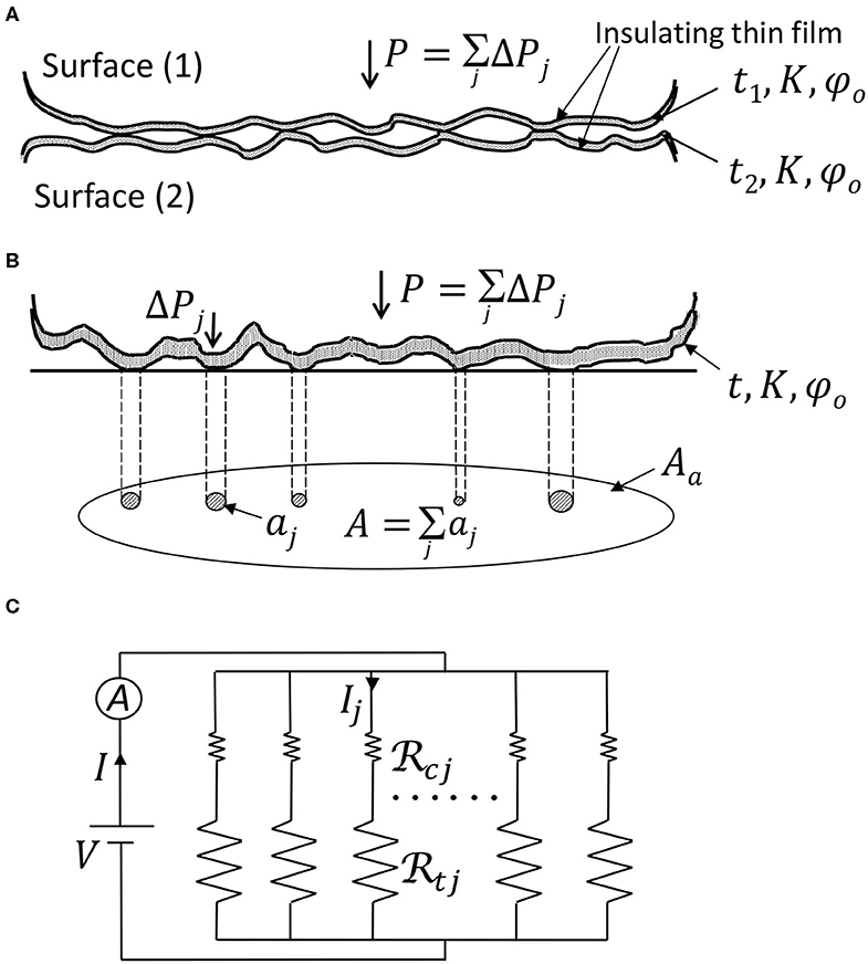
Figure 10. (A) Contact of two rough surfaces separated by an insulating thin film, (B) equivalent contact model of rough surfaces separated by a thin-film insulator, and (C) electrical analog of the contact interface consisting of parallel constriction and tunneling resistances of the asperity microcontacts.
For the electrons to pass through a microcontact interface, they must overcome the energy barrier of the insulating film by entering its conduction band. However, according to quantum theory, there is a finite probability for electrons with energy even less than the insulator's energy barrier to tunnel through the insulating film. For very small voltage drop Vi(Vi ≈ 0) across the jth asperity microcontact with area aj, is ohmic and is given by (Simmons, 1963; Kogut and Komvopoulos, 2004b)
where ΔS = S2 − S1 and
where S1 and S2 are the limits of the energy barrier at the Fermi level and φ is the mean barrier height.
Equation (40) indicates that is inversely proportional to aj. Moreover, numerical results show that increases with t, K, and φ0 (Simmons, 1963).
When the voltage drop Vi across an asperity microcontact is not very small, is non-ohmic and is given by (Simmons, 1963; Kogut and Komvopoulos, 2004b)
where
Equation (44) shows a non-linear current-voltage relation and an inverse proportionality between and aj, while Equations (45–47) indicate that ΔS and φ are functions of Vi. Moreover, numerical results show that the non-ohmic resistance given by Equation (44) decreases with increasing voltage (Simmons, 1963).
The tunnel resistance given by Equations (40, 44) can be written in dimensionless form as following,
In the presence of a thin insulating film at the contact interface of two conductive rough surfaces, , especially for highly conductive surfaces, even when Vi is not small (Simmons, 1963; Kogut and Komvopoulos, 2004b). Therefore, in this case it may be assumed that . Consequently, when the contacting surfaces are separated by a thin-film insulator, the dimensionless (total) electrical contact resistance can be obtained by numerical integration, i.e.,
where is given by Equation (48) and aj is given in terms of by Equation (12, 16, or 19), depending on the mode of deformation at each asperity microcontact. Equations (5, 8, 17–19, 40–49) indicate that the dimensionless ECR depends on the fractal parameters D, G, and γ, the effective mechanical properties E and Y, the thickness t and electrical properties K and φ0 of the insulating film, the voltage drop Vi (if it is not very small), the truncated contact area A′, and the apparent contact area Aa.
For additional insight into the multiscale electromechanics of contact interfaces, results of the dimensionless electrical contact resistance of elastic and fully plastic asperity microcontacts obtained by an iterative procedure in a previous study (Kogut and Komvopoulos, 2004b) are reproduced in Figure 11. Figure 11A shows the effect of the insulating film thickness t on the variation of the dimensionless electrical contact resistance with contact load P* for D = 2.3, , E/Y = 106, and I = 5 μA. The decreasing trend of the ECR is attributed to the formation of more and larger asperity microcontacts with increasing load, providing more electron paths across the contact interface. The variation of the ECR comprises an initial stage of rapid decay and a succeeding stage of gradual decrease, a consequence of the multiscale surface roughness effect. For relatively light contact loads (P* < 0.5), surface contact is mostly confined at small asperities residing on top of large asperities; thus, the real contact area is very small and electron flow through the contact interface is greatly restricted. In the high-load range (P* > 0.5), however, the formation of more and larger asperity microcontacts increases electron flow significantly. Figure 11A also shows that the ECR decreases with the insulating film thickness. This trend is attributed to the enhancement of electron tunneling with decreasing insulating film thickness. Figure 11B shows the dimensionless electrical contact resistance vs. contact load P*and current I for D = 2.3, G* = 10−7, E/Y = 106, K = 6, t = 10 Å, and φ0 = 2 eV. The results for I ≈ 0 were obtained from Equation (40), whereas all other results were obtained from Equation (44). The decrease of with increasing I is attributed to the decrease of with Vi [Equation (44)]. This is attributed to the ECR drop with increasing P*, which, for a fixed I, leads to a smaller voltage drop Vi. Consequently, decreases because is enhanced by the decrease of Vi. This voltage compensation mechanism represents another manifestation of the multiscale roughness effect in contact electromechanics. Although the solutions corresponding to I ≈ 0 and I = 0.1 μA are in good agreement, the high voltage drop at light loads invalidates the assumption of Vi ≈ 0, despite the very low current (I = 0.1 μA). The noticeable decrease of the ECR by almost two orders of magnitude in the case of low current (I ≤ 0.1 μA) is due to the ohmic behavior of [Equation (40)], whereas the less pronounced ECR decrease in the cases of high current (I ≥ 2.5 μA) is a consequence of the voltage dependence of [Equation (44)] and the voltage compensation mechanism. Figure 11C shows the dimensionless real contact area A* as a function of the dimensionless electrical contact resistance for a wide range of fractal parameters and material properties. Importantly, despite significant differences in fractal parameters and electrical/mechanical properties, all the data lay on the same curve, even for the cases of no small voltage. This suggests that the dependence of A* on is not affected by surface topography and material properties. By curve fitting the data shown in Figure 11C, the following general relation can be obtained (Kogut and Komvopoulos, 2004b)
where B and β are functions of the insulating film properties (i.e., K, t, and φ0) and the current I used to measure the ECR (i.e., the voltage drop V across the contact interface). The ECR generally decreases with increasing fractal dimension, contact load, and current flow and with decreasing fractal roughness, insulating film thickness and dielectric constant, and height of energy barrier.
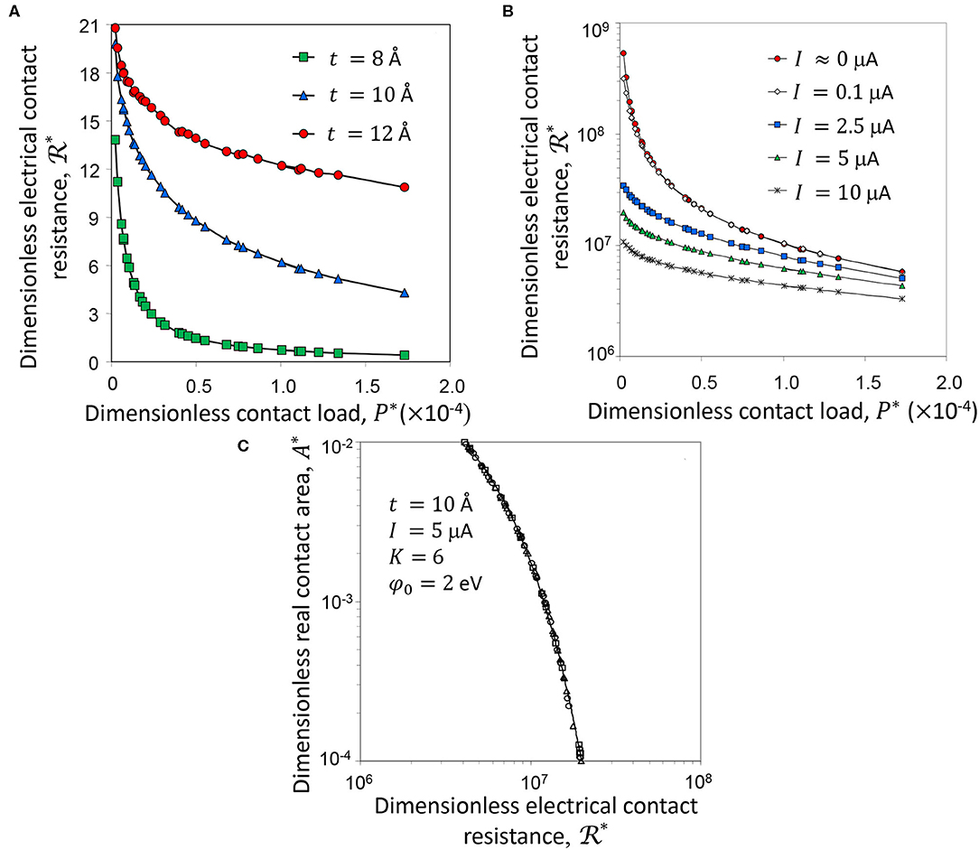
Figure 11. (A) Dimensionless electrical contact resistance vs. dimensionless contact load P* for t = 8, 10, and 12 Å (D = 2.3, G* = 10−7, E/Y = 106, K = 6, φ0 = 2 eV, and I = 5 μA), (B) dimensionless electrical contact resistance vs. dimensionless contact load P* for I = 0–10 μA (D = 2.3, G* = 10−7, E/Y = 106, t = 10 Å, K = 6, φ0 = 2 eV), and (C) dimensionless contact area A* vs. dimensionless electrical contact resistance (2 < D < 2.5, 10−11 ≤ G* ≤ 10−7, E/Y = 106, 288, and 391, t = 10 Å, K = 6, φ0 = 2 eV, and I = 5 μA) (Kogut and Komvopoulos, 2004b).
In view of the results shown in Figure 11 and Equation (50), it may be inferred that the mechanical and electrical behaviors of contact interfaces are intertwined. Thus, the flow chart shown in Figure 12 is proposed for the design of contact-mode electromechanical devices. Specifically, the contact geometry (either point or line contact) and the topography of the contacting surfaces are first used to estimate the apparent contact area and the fractal parameters [Equations (1)–(4)], respectively. This information and the mechanical properties of the surfaces are then introduced into the contact mechanics analysis to obtain the dimensionless contact load and contact area of each asperity microcontact from the contact equations of the appropriate deformation mode [Equations (5)–(22)], the dimensionless contact load [Equation (23)] and contact area [Equation (24)] by numerical integration, and the size distribution function and critical truncation areas demarcating the elastic, elastic-plastic, and fully plastic modes of deformation at the asperity scale. The next step is to determine the ECR based on the electrical properties of the contacting surfaces, the applied voltage, the topography and mechanics information obtained in the previous step, and the current [Equations (38–49)] and establish the relation of the ECR with the dimensionless real contact area A* [Equation (50)] and, through Equations (11–22), with the dimensionless contact load P*. Thus, a comprehensive electromechanics analysis of the contact interface can be achieved by using the correlations of the ECR with the real contact area and contact load, which are interdependent. If the electrical performance does not meet the desired specifications, the flow chart shown in Figure 12 provides a means of modifying the topography and/or electromechanical properties of the surfaces so that the new contact load and real contact area to produce electrical characteristics that satisfy the application requirements.
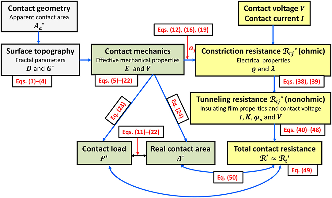
Figure 12. Electromechanics flow chart for rough (fractal) contact interfaces. Dimensionless parameters are indicated with an asterisk.
When electric current flows through a conductor, electric power is dissipated in the form of thermal power due to electron energy loss caused by collisions with the conductor atoms. The heating generated by this loss of electric energy (Joule heating) is of high importance in electronics because it can negatively impact on-chip integration of electronic components. Thermal effects are even more significant in contact-mode electromechanical devices, such as switches and relays, because the inconsistent restriction of current flow through contact interfaces can seriously affect their performance and durability. For instance, the temperature at the contact interface of high-current electromechanical relays may increase to a level causing melting and hot welding of the contacting surfaces, hence severely limiting the lifetime of the device. Another example is the detrimental effect of arcing on the performance of high-speed switches, where contact bouncing during open/close of the device can re-establish arcing, consequently prolonging the deleterious effect of arc heating. The ECR theory presented above can be used to analyze thermal effects due to Joule heating, implying a coupling between electrical and thermal analysis of electronic contacts. Considering that thermal effects can also affect the real contact area and, in turn, the mechanics of the contact interface, fully coupled thermo-electro-mechanical (TEM) analyses must be developed by intertwining mechanics, thermal, and electrical contact theories, such as those presented herein, for example, and employing an iterative procedure among key TEM parameters. This concept provides impetus for the advancement of new theoretical treatments, which can lead to the construction of 3D TEM maps that can be used to optimize the design of micro/nanoelectronic devices.
Conclusions
A fundamental understanding of the mechanics, heat transfer, and electrical conduction of contact interfaces is of critical importance to a wide range of traditional and contemporary technologies. The intricacies of underlying physical mechanisms controlling contact interface phenomena require a multiscale treatment that takes into account the hierarchical structure of surface topography. The integration of realistic, scale-invariant surface description methods, such as those derived from fractal geometry, with hybrid analytical-numerical approaches that use constitutive modeling at the asperity scale is essential for studying contact interface phenomena at different length scales. Such methodology is of particular importance because it can affect the design and operation efficacy of devices with contacting components. A general multiscale theoretical treatment of contact interfaces that exhibit self-affine behavior was presented in this article. The central objective was to introduce a rigorous mathematical treatment of the fundamental mechanical, thermal, and electrical characteristics of contact interfaces exhibiting multiscale roughness. The present analysis can be extended to include the influence of the deformation of neighboring asperity microcontacts, sliding friction, and thermoelectric effects on contact deformation by introducing more sophisticated contact mechanics treatments. Surface topography, mechanics, thermal, and electrical parameters were used in dimensionless form to analyze the mechanical, thermal, and electrical characteristics of contact interfaces exhibiting multiscale roughness. The correlations established among various dimensionless quantities provide a means of real-time monitoring of important contact interface parameters, such as the real contact area, thermal contact conductance, and electrical contact resistance, as demonstrated by the flow charts presented herein. Perhaps, the most important contribution of this paper is the establishment of a theoretical framework for thermo-electro-mechanics studies of contact interfaces.
Data Availability Statement
The datasets generated for this study are available on request to the corresponding author.
Author Contributions
The author confirms being the sole contributor of this work and has approved it for publication.
Conflict of Interest
The author declares that the research was conducted in the absence of any commercial or financial relationships that could be construed as a potential conflict of interest.
References
Archard, J. F. (1953). Contact and rubbing of flat surfaces. J. Appl. Phys. 24, 981–988. doi: 10.1063/1.1721448
Archard, J. F. (1957). Elastic deformation and the laws of friction. Proc. R. Soc. Lond. A 243, 190–205. doi: 10.1098/rspa.1957.0214
Ausloos, M., and Berman, D. H. (1985). A multivariate Weierstrass-Mandelbrot function. Proc. R. Soc. Lond. A 400, 331–350. doi: 10.1098/rspa.1985.0083
Barber, J. R. (2003). Bounds on the electrical resistance between contacting elastic rough bodies. Proc. R. Soc. Lond. A 459, 53–66. doi: 10.1098/rspa.2002.1038
Berry, M. V., and Lewis, Z. V. (1980). On the Weierstrass-Mandelbrot fractal function. Proc. R. Soc. Lond. A 370, 459–484. doi: 10.1098/rspa.1980.0044
Bhargava, V., Hahn, G. T., and Rubin, C. A. (1985a). An elastic-plastic finite element model of rolling contact Part 1: analysis of single contacts. ASME J. Appl. Mech. 52, 67–74. doi: 10.1115/1.3169028
Bhargava, V., Hahn, G. T., and Rubin, C. A. (1985b). An elastic-plastic finite element model of rolling contact Part 2: analysis of repeated contacts. ASME J. Appl. Mech. 52, 75–82. doi: 10.1115/1.3169030
Bhushan, B., and Dugger, M. T. (1990). Real contact area measurements on magnetic rigid disks. Wear 137, 4–50. doi: 10.1016/0043-1648(90)90016-4
Biwa, S., and Storåkers, B. (1995). An analysis of fully plastic Brinell indentation. J. Mech. Phys. Solids 43, 1303–1333. doi: 10.1016/0022-5096(95)00031-D
Blackmore, D., and Zhou, G. (1998a). A new fractal model for anisotropic surfaces. Int. J. Mach. Tools Manuf. 38, 551–557. doi: 10.1016/S0890-6955(97)00101-6
Blackmore, D., and Zhou, J. G. (1998b). Fractal analysis of height distributions of anisotropic rough surfaces. Fractals 6, 43–58. doi: 10.1142/S0218348X98000067
Ciavarella, M., and Demelio, G. (2001). Elastic multiscale contact of rough surfaces: Archard's model revisited and comparisons with modern fractal models. ASME J. Appl. Mech. 68, 496–498. doi: 10.1115/1.1352016
Ciavarella, M., Demelio, G., Barber, J. R., and Jang, Y. H. (2000). Linear elastic contact of the Weierstrass profile. Proc. R. Soc. Lond. A 456, 387–405. doi: 10.1098/rspa.2000.0522
Ciavarella, M., Murolo, G., and Demelio, G. (2004). The electrical/thermal conductance of rough surfaces–the Weierstrass-Archard multiscale model. Int. J. Solids Struct. 41, 4107–4120. doi: 10.1016/j.ijsolstr.2004.02.048
Cooper, M. G., Mikic, B. B., and Yovanovich, M. M. (1969). Thermal conduct conductance. Int. J. Heat Mass. Transfer 12, 279–300. doi: 10.1016/0017-9310(69)90011-8
Dumas, G., and Baronet, C. N. (1971). Elastoplastic indentation of a half-space by an infinitely long rigid circular cylinder. Int. J. Mech. Sci. 13, 519–530. doi: 10.1016/0020-7403(71)90039-7
Eguchi, M., Shibamiya, T., and Yamamoto, T. (2009). Measurement of real contact area and analysis of stick/slip region. Tribol. Int. 42, 1781–1791. doi: 10.1016/j.triboint.2009.04.046
Follansbee, P. S., and Sinclair, G. B. (1984). Quasi-static normal indentation of an elasto-plastic half-space by a rigid sphere-I. Analysis. Int. J. Solids Struct. 20, 81–91. doi: 10.1016/0020-7683(84)90078-7
Gong, Z.-Q., and Komvopoulos, K. (2004). Mechanical and thermomechanical elastic-plastic contact analysis of layered media with patterned surfaces. ASME J. Tribol. 126, 9–17. doi: 10.1115/1.1609487
Gong, Z.-Q., and Komvopoulos, K. (2005). Thermomechanical analysis of semi-infinite solid in sliding contact with a fractal surface. ASME J. Tribol. 127, 331–342. doi: 10.1115/1.1792691
Greenwood, J. A. (1966). Constriction resistance and the real area of contact. Br. J. Appl. Phys. 17, 1621–1632. doi: 10.1088/0508-3443/17/12/310
Greenwood, J. A., and Williamson, J. B. P. (1966). Contact of nominally flat surfaces. Proc. R. Soc. Lond. A 295, 300–319. doi: 10.1098/rspa.1966.0242
Hardy, C., Baronet, C. N., and Tordion, G. V. (1971). The elasto-plastic indentation of a half-space by a rigid sphere. Int. J. Num. Meth. Eng. 3, 451–462. doi: 10.1002/nme.1620030402
Hertz, H. (1882). Über die berührung fester elastischer körper (On the contact of rigid elastic solids). J. Reine Angew. Mathematik 92, 156–171.
Hertz, H. (1896). “On the contact of elastic solids,” in Miscellaneous Papers by H. Hertz, eds D. E. Jones and G. A. Schott (London: Macmillan), 146–162. doi: 10.1515/crll.1882.92.156
Hill, R., Storåkers, B., and Zdunek, A. B. (1989). A theoretical study of the Brinell hardness test. Proc. R. Soc. Lond. A 423, 301–330. doi: 10.1098/rspa.1989.0056
Holm, R. (1967). Electrical Contacts: Theory and Application, 4th Edn. New York, NY: Springer. doi: 10.1007/978-3-662-06688-1
Johnson, K. L. (1985). Contact Mechanics. Cambridge, UK: Cambridge University Press. doi: 10.1017/CBO9781139171731
Kadin, Y., Kligerman, Y., and Etsion, I. (2006a). Unloading an elastic-plastic contact of rough surfaces. J. Mech. Phys. Solids 54, 2652–2674. doi: 10.1016/j.jmps.2006.04.013
Kadin, Y., Kligerman, Y., and Etsion, I. (2006b). Multiple loading-unloading of an elastic-plastic spherical contact. Int. J. Solids Struct. 43, 7119–7127. doi: 10.1016/j.ijsolstr.2006.03.006
Kogut, L., and Komvopoulos, K. (2003). Electrical contact resistance theory for conductive rough surfaces. J. Appl. Phys. 94, 3153–3162. doi: 10.1063/1.1592628
Kogut, L., and Komvopoulos, K. (2004a). Analysis of the spherical indentation cycle for elastic-perfectly plastic solids. J. Mater. Res. 19, 3641–3653. doi: 10.1557/JMR.2004.0468
Kogut, L., and Komvopoulos, K. (2004b). Electrical contact resistance theory for conductive rough surfaces separated by a thin insulating film. J. Appl. Phys. 95, 576–585. doi: 10.1063/1.1629392
Kogut, L., and Komvopoulos, K. (2005). Analytical current-voltage relationships for electron tunneling across rough interfaces. J. Appl. Phys. 97:073701. doi: 10.1063/1.1866472
Komvopoulos, K. (2012). “Adhesive wear,” in Handbook of Lubrication and Tribology, Volume II: Theory and Design, 2nd Edn, ed R. W. Bruce (Boca Raton, FL: CRC Press), 7(1)–7(2). doi: 10.1201/b12265-9
Komvopoulos, K., and Yan, W. (1998). Three-dimensional elastic-plastic fractal analysis of surface adhesion in microelectromechanical systems. ASME J. Tribol. 120, 808–813. doi: 10.1115/1.2833783
Komvopoulos, K., and Ye, N. (2001). Three-dimensional contact analysis of elastic-plastic layered media with fractal surface topographies. ASME J. Tribol. 123, 632–640. doi: 10.1115/1.1327583
Kral, E. R., Komvopoulos, K., and Bogy, D. B. (1993). Elastic-plastic finite element analysis of repeated indentation of a half-space by a rigid sphere. ASME J. Appl. Mech. 60, 829–841. doi: 10.1115/1.2900991
Kulkarni, S. M., Hahn, G. T., Rubin, C. A., and Bhargava, V. (1990). Elastoplastic finite element analysis of three-dimensional, pure rolling contact at the shakedown limit. ASME J. Appl. Mech. 57, 57–65. doi: 10.1115/1.2888324
Kulkarni, S. M., Hahn, G. T., Rubin, C. A., and Bhargava, V. (1991). Elasto-plastic finite element analysis of three-dimensional pure rolling contact above the shakedown limit. ASME J. Appl. Mech. 58, 347–353. doi: 10.1115/1.2897192
Le Mehaute, A. (1991). “Why should the world be fractal?” in Fractals: Non-Integral Dimensions and Applications, ed G. Cherbit (New York, NY: Wiley), 130–134.
Lee, A., and Komvopoulos, K. (2018). Dynamic spherical indentation of elastic-plastic solids. Int. J. Solids Struct. 146, 180–191. doi: 10.1016/j.ijsolstr.2018.03.028
Lee, A., and Komvopoulos, K. (2019). Dynamic spherical indentation of strain hardening materials with and without strain rate-dependent deformation behavior. Mech. Mater. 133, 128–137. doi: 10.1016/j.mechmat.2018.12.002
Lumbantobing, A., Kogut, L., and Komvopoulos, K. (2004). Electrical contact resistance as a diagnostic tool for MEMS contact interfaces. J. Microelectromech. Syst. 13, 977–987. doi: 10.1109/JMEMS.2004.838388
Maegawa, S., Itoigawa, F., and Nakamura, T. (2015). Optical measurements of real contact area and tangential contact stiffness in rough contact interface between an adhesive soft elastomer and a glass plate. Bullet. JSME J. Adv. Mech. Des. Syst. Manuf. 9:15–00253. doi: 10.1299/jamdsm.2015jamdsm0069
Majumdar, A., and Bhushan, B. (1991). Fractal model of elastic-plastic contact between rough surfaces. ASME J. Tribol. 113, 1–11. doi: 10.1115/1.2920588
Majumdar, A., and Tien, C. L. (1990). Fractal characterization and simulation of rough surfaces. Wear 136, 313–327. doi: 10.1016/0043-1648(90)90154-3
Malliaris, A., and Turner, D. T. (1971). Influence of particle size on the electrical resistivity of compacted mixtures of polymeric and metallic powders. J. Appl. Phys. 42, 614–618. doi: 10.1063/1.1660071
Mesarovic, S. D., and Fleck, N. A. (1999). Spherical indentation of elastic-plastic solids. Proc. R. Soc. Lond. A 455, 2707–2728. doi: 10.1098/rspa.1999.0423
Mikrajuddin, A., Shi, F. G., Kim, H. K., and Okuyama, K. (1999). Size-dependent electrical constriction resistance for contacts of arbitrary size: from Sharvin to Holm limits. Mater. Sci. Semicon. Proces. 2, 321–327. doi: 10.1016/S1369-8001(99)00036-0
Nayak, P. R. (1973). Random process model of rough surfaces in plastic contact. Wear 26, 305–333. doi: 10.1016/0043-1648(73)90185-3
Paggi, M., and Barber, J. R. (2011). Contact conductance of rough surfaces composed of modified RMD patches. Int. J. Heat Mass Trans. 54, 4664–4672. doi: 10.1016/j.ijheatmasstransfer.2011.06.011
Park, Y. J., and Pharr, G. M. (2004). Nanoindentation with spherical indenters: finite element studies of deformation in the elastic-plastic transition regime. Thin Solid Films 447, 246–250. doi: 10.1016/S0040-6090(03)01102-7
Persson, B. N. J. (2001). Theory of rubber friction and contact mechanics. J. Chem. Phys. 115, 3840–3861. doi: 10.1063/1.1388626
Persson, B. N. J., Bucher, F., and Chiaia, B. (2002). Elastic contact between randomly rough surfaces: comparison of theory with numerical results. Phys. Rev. B 65:184106. doi: 10.1103/PhysRevB.65.184106
Sayles, R. S., and Thomas, T. R. (1978). Surface topography as a nonstationary random process. Nature 271, 431–434. doi: 10.1038/271431a0
Schneegans, O., Houzé, F., Meyer, R., and Boyer, L. (1998). Study of the local electrical properties of metal surfaces using an AFM with a conducting probe. IEEE Trans. Compon. Packag. Manuf. Technol. A 21, 76–81. doi: 10.1109/95.679036
Sick, J.-H., and Ostermeyer, G.-P. (2007). In situ measurement of contact area in coated surfaces. WIT Trans. Eng. Sci. 55, 259–270. doi: 10.2495/SECM070251
Simmons, J. G. (1963). Generalized formula for the electric tunnel effect between similar electrodes separated by a thin insulating film. J. Appl. Phys. 34, 1793–1803. doi: 10.1063/1.1702682
Sinclair, G. B., Follansbee, P. S., and Johnson, K. L. (1985). Quasi-static normal indentation of an elasto-plastic half-space by a rigid sphere-II. Results. Int. J. Solids Struct. 21, 865–888. doi: 10.1016/0020-7683(85)90039-3
Song, Z., and Komvopoulos, K. (2013). Elastic-plastic spherical indentation: deformation regimes, evolution of plasticity, and hardening effect. Mech. Mater. 61, 91–100. doi: 10.1016/j.mechmat.2013.01.003
Song, Z., and Komvopoulos, K. (2014). Contact mechanics analysis of oscillatory sliding of a rigid fractal surface against an elastic-plastic half-space. Philos. Mag. 94, 3215–3233. doi: 10.1080/14786435.2014.953618
Wang, S., and Komvopoulos, K. (1994a). A fractal theory of the interfacial temperature distribution in the slow sliding regime: Part I-Elastic contact and heat transfer analysis. ASME J. Tribol. 116, 812–823. doi: 10.1115/1.2927338
Wang, S., and Komvopoulos, K. (1994b). A fractal theory of the interfacial temperature distribution in the slow sliding regime: Part II - Multiple domains, elastoplastic contacts and applications. ASME J. Tribol. 116, 824–832. doi: 10.1115/1.2927341
Wang, S., and Komvopoulos, K. (1995). A fractal theory of the interfacial temperature distribution at elastic contacts of fast sliding surfaces. ASME J. Tribol. 117, 203–215. doi: 10.1115/1.2831227
Wang, S., Yin, X., Wang, H., and Komvopoulos, K. (2018). A generalized mechanics theory of idealized rough surfaces under dry and liquid-mediated plastic contact conditions. Int. J. Solids Struct. 155, 304–318. doi: 10.1016/j.ijsolstr.2018.09.016
Yan, H., Voorhees, P. W., and Xin, H. L. (2020). Nanoscale x-ray and electron tomography. MRS Bullet. 45, 264–271. doi: 10.1557/mrs.2020.90
Yan, S. L., and Li, L. Y. (2003). Finite element analysis of cyclic indentation of an elastic-perfectly plastic half-space by a rigid sphere. Proc. Inst. Mech. Eng. Part C: J. Mech. Eng. Sci. 217, 505–514. doi: 10.1243/095440603765226795
Yan, W., and Komvopoulos, K. (1998). Contact analysis of elastic-plastic fractal surfaces. J. Appl. Phys. 84, 3617–3624. doi: 10.1063/1.368536
Yang, J., and Komvopoulos, K. (2005). A mechanics approach to static friction of elastic-plastic fractal surfaces. ASME J. Tribol. 127, 315–324. doi: 10.1115/1.1828080
Ye, N., and Komvopoulos, K. (2003). Three-dimensional finite element analysis of elastic-plastic layered media under thermomechanical surface loading. ASME J. Tribol. 125, 52–59. doi: 10.1115/1.1497360
Keywords: asperity microcontact, contact interface, deformation, electrical contact resistance, fractal surfaces, multiscale surface roughness, temperature rise, thermal contact conductance
Citation: Komvopoulos K (2020) A Multiscale Theoretical Analysis of the Mechanical, Thermal, and Electrical Characteristics of Rough Contact Interfaces Demonstrating Fractal Behavior. Front. Mech. Eng. 6:36. doi: 10.3389/fmech.2020.00036
Received: 10 March 2020; Accepted: 11 May 2020;
Published: 01 July 2020.
Edited by:
Yang Xu, University of Glasgow, United KingdomReviewed by:
Ali Ghanbarzadeh, University of Leeds, United KingdomQian Jane Wang, Northwestern University, United States
Copyright © 2020 Komvopoulos. This is an open-access article distributed under the terms of the Creative Commons Attribution License (CC BY). The use, distribution or reproduction in other forums is permitted, provided the original author(s) and the copyright owner(s) are credited and that the original publication in this journal is cited, in accordance with accepted academic practice. No use, distribution or reproduction is permitted which does not comply with these terms.
*Correspondence: Kyriakos Komvopoulos, a3lyaWFrb3NAbWUuYmVya2VsZXkuZWR1