 Hiroaki Ichihashi
 Yudai Yamasaki
 Yoshitane Takashima
 Takahiro Sako
- 1Department of Mechanical Engineering, The University of Tokyo, Tokyo, Japan
- 2Energy Technology Laboratories, OSAKA GAS CO., LTD, Osaka, Japan
The dual-fuel engine (DFE) has been focused on in order to improve its efficient use of natural gas. It has been reported that in DFE the combustion efficiency of the natural gas decreases at a low load. In an attempt to tackle this problem, it has been reported that a multi-stage diesel injection can improve the combustion efficiency of natural gas at a low load. The aim of this research is, therefore, to explain the mechanism for improving combustion efficiency with a multi-stage diesel injection and to develop a control model that predicts engines' combustion efficiency by multi-stage injection. Additionally, a controller was developed using the control model to improve the combustion efficiency by changing the diesel injection conditions. Experimental results show that the controller improves combustion efficiency. Furthermore, taking in to account the heat ratio of natural gas to diesel fuel in addition to combustion efficiency, it has been shown that it is possible to design a controller to leverage the advantage of DFE, which reduces the quantity of fossil fuels.
Introduction
Natural gas has a lower environmental effect compared to diesel or gasoline fuel as its CO2 emission per unit heat value is lower. The development of a dual-fuel engine (DFE), a gas engine, has been a popular topic for the efficient use of natural gas. DFE combusts natural gas through the self-ignition of a small quantity of diesel fuel. It is known that under high load, DFE has higher thermal efficiency compared to the spark ignition gas engine, and the emission of NOx and soot are lower compared to diesel engines. However, DFE is also known to have poor combustion efficiency of natural gas under a low load and to worsen the thermal efficiency and emission of total hydrocarbon (THC) (Papagiannakis and Hountalas, 2004). Hence, in order to utilize the advantage of natural gas in DFE, improving the combustion efficiency under a low load is important to obtain high thermal efficiency and low emission of THC. To improve the combustion in low load, combustion characteristics under various operating conditions have been clarified so far. By introducing a multi-stage diesel injection using the common rail system, high thermal efficiency and low THC emission can be achieved, as the combustion efficiency improves, and by adjusting the injection timing and injection pressure, low NOx emission and stable combustion can be realized (Carlucci et al., 2006, 2015; Min et al., 2016; Yang and Zeng, 2018; Yousefi et al., 2018; Ichihashi et al., 2019). Also, it has been reported that, by using an EGR (Exhaust Gas Recirculation) system and a turbocharger system, thermal efficiency, and emission characteristics improved under low loads (Abdelaal and Hegab, 2012; Kojima et al., 2016; Krishnan et al., 2016). To date, several studies have been undertaken under individual conditions to improve combustion efficiency in low load, but the consideration toward controlling DFE as an engine system is insufficient. Traditionally, map control has been used to control an engine as a system. However, in DFE, a large number of experiments are required to construct the control map, since DFE has more manipulated variables than spark ignition gas engines or diesel engines. To solve this problem, a control method called model-based control appears to be usable, but no existing control model assumed various operation conditions, such as multi-stage diesel injection. Therefore, in this research, a control model was developed to predict the combustion in DFE under a low load, assuming various operation conditions and a control system was implemented using that model. As explained above, the diesel injection strategy has the potential to improve combustion efficiency in low load, so the purpose of the controller implemented in this research is to obtain the diesel injection condition that maximizes the combustion efficiency.
The Target Combustion in DFE
First, a diesel injection strategy was organized to clarify the target combustion that realizes high thermal efficiency and low emissions under low load in DFEs. Ichihashi et al. (2019) reported that a triple-stage diesel injection, including an early injection, improved the combustion efficiency. The mechanism for improving the combustion efficiency assumes that diesel fuel spreads in the combustion chamber from the early injection, and the number of ignition points of natural gas increases. However, it is not sufficient to confirm the change in the number of ignition points by simply analyzing the in-cylinder pressure.
Therefore, to clarify the mechanism for improving combustion efficiency and to decide the modeling concept for DFE with multiple injections, experiments with an optical access engine (see Figure 1) were carried out. The engine specifications of the optical access engine are shown in Table 1. OH radical luminescence photographs by changing the diesel injection condition using the optical access engine were taken and analyzed to clarify the ignition area. The knowledge obtained from the analysis of the photograph was mainly reflected to express the combustion of the natural gas.

Figure 1. Visualization engine setup.
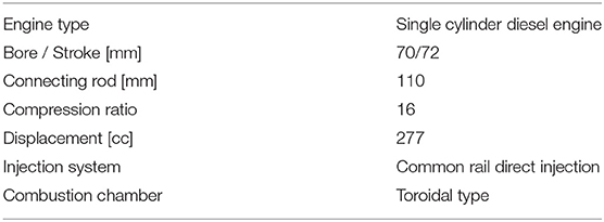
Table 1. The engine specifications for visualization engine.
The self-emission of OH radical was captured by setting a bandpass filter (310 nm) and an image intensifier before a high-speed camera. The exposure time of the high-speed camera was set to 60 μs. The diesel injection condition was set to single (θMain = −10 deg. ATDC), double (Case1: θPre = −50 deg. ATDC, θMain = −10 deg. ATDC, Case2: θPre = −90 deg. ATDC, θMain = −10 deg. ATDC), and triple (θPilot = −90 deg. ATDC, θPre = −50 deg. ATDC, θMain = −10 deg. ATDC) to observe the effect of a multi-stage injection. By implementing a multi-stage diesel injection, including an early injection, the number of combustion starting points increased (Figure 2). In a single injection, the combustion started only from the upper end of the combustion chamber. On the other hand, in double injection case 1 and triple injection, the combustion started at 2~3 points. It shows that, with a multi-stage diesel injection including an early injection, the ignition points of natural gas increased. However, as seen in double injection (case 2), the ignition points of natural gas did not increase in some injection timings. This shows that the diesel injection strategy is important for increasing ignition points and achieving high combustion efficiency.
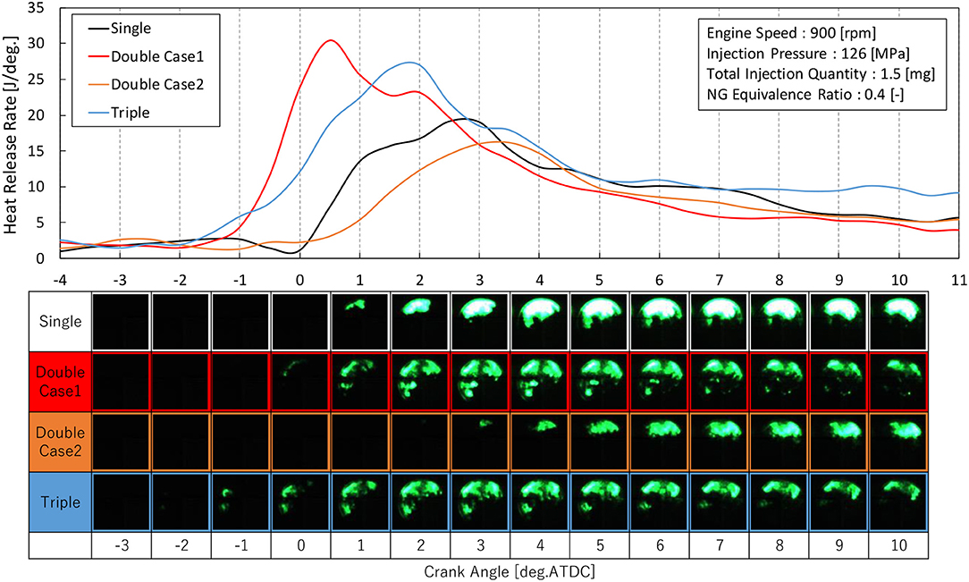
Figure 2. Heat release rate and pictures of the combustion chamber.
DFE Control Model
Since the diesel injection strategy is important to achieve high combustion efficiency, constructing a controller to derive the injection condition that maximizes the combustion efficiency is important. To implement this controller in DFE, first, a control model for DFE was constructed. This control model is required to predict the combustion efficiency for various operation conditions, especially the injection conditions under low load, and for a multi-stage diesel injection including an early injection. Therefore, the inputs of this model are the operating conditions that can be obtained from the ECU (Engine Control Unit), and the output is the combustion efficiency. Also, to use the model for iterative calculation for optimization, the calculation load needs to be minimal. To minimize the calculation overhead, the model was designed to only predict discrete points in the engine cycle. Such a concept to calculate several discretized points was proposed for HCCI (Homogeneous Charge Compression Ignition) engine by Ravi et al. (2006). The author's group also developed models for advanced diesel combustion based on such a concept (Yasuda et al., 2016; Yamasaki et al., 2019a) and the controllers were designed using the model (Yamasaki et al., 2019b). The developed controller for the advanced diesel engine was validated in engine experiments (Takahashi et al., 2019). It has been clarified that such control-oriented models calculating discretized points are useful to construct a model-based control system for engines. However, in DFE, two kinds of combustion, the self-ignition of diesel fuel and flame propagation of gas fuel, occur simultaneously, and this has become a complicated phenomenon and it was thought to be difficult to predict the combustion only by discrete points. Therefore, the developed model in this paper employs both the discrete model and the continuous model. The continuous model predicts the combustion only in the combustion process (IGN~EC). The discrete points (see Table 2) and each process, including the combustion process in the cycle, are shown in Figure 3. Also, the calculation flow of the DFE control model is shown in Figure 4.
Table 2. Discrete points of the DFE combustion control model.
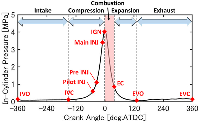
Figure 3. The discrete points and processes in the cycle.
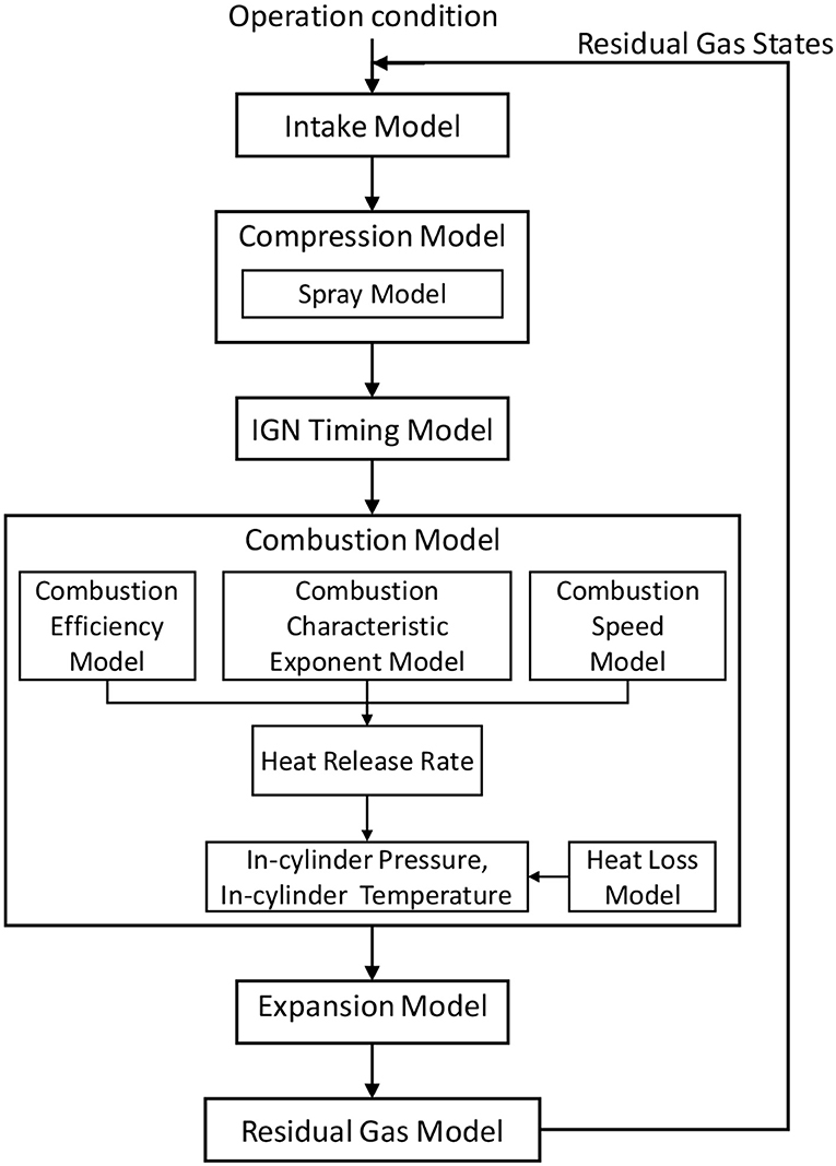
Figure 4. Calculation flow of the DFE combustion control model.
The following explains the detail of the model. To consider the effect of residual gas, the calculation was done 10 times from the intake model to the residual gas model.
In the intake model, the pressure and temperature at IVC was predicted as,
Where A ~ G are coefficients which need to be adapted, Pboost is the boost pressure, Ne is the engine speed in rpm, Tintake is the temperature of fresh air, TRG is the temperature of residual gas, rEGR is the EGR ratio, and Qprevdiesel and FprevNG are the quantities of fuel input in the previous cycle. In this model, the intake sub-model was developed using multiple regression analysis. The pressure at IVC is thought to be affected by the boost pressure and the engine speed, since the time frame for the intake valves to remain open decreases as the engine speed increases. The temperature at the IVC was explained by the temperature of each gas, which constitutes the in-cylinder gas. Also, the amount of fuel input in the previous cycle was included since the temperature of the cylinder wall changes and the amount of heat transfer from the cylinder wall to the in-cylinder gas changes as well. In addition, the engine speed was included since the time for heat loss will change.
Then the total amount of substance of the in-cylinder gas is calculated using the ideal gas equation.
Using the total amount of substance at IVC, the amount of substance for each composition is calculated.
Where nRG and nNG are the quantity of substance of residual gas and input natural gas. In this research, the composition of the EGR gas was assumed to be the same as the residual gas.
In the compression model (IVC ~ INJ), the pressure, temperature, and quantity of substance for each composition are predicted at each injection timing. The pressure and temperature are predicted from polytropic change. The polytropic index is calculated from the temperature of IVC and engine speed, which are considered to affect the heat loss during the compression process. The composition is assumed to be the same as the IVC. A, B, and C are coefficients that need to be adapted.
In the spray model, the volume of the diesel spray was calculated using the Reitz spray shape model (Reitz and Bracco, 1979). LSpray is the penetration and tan(φ) is the spray angle.
In the ignition timing model (INJ ~ IGN), ignition timing was predicted using the Livengood-Wu ignition model (Livengood and Wu, 1995).
Where [Diesel] and [O2] are the concentrations of diesel fuel and oxygen and T is the temperature of the in-cylinder gas at the main injection. A, B, C, and E are coefficients that need to be adapted. The pressure and temperature at IGN are predicted from polytropic change, as shown in Equations (6, 7) and the composition is assumed to be the same as each injection timing.
In the combustion model (IGN ~ EC), Wiebe function (Vibe, 1970) was used to predict the history of heat release rate, in-cylinder pressure, and temperature. Wiebe function predicts the rate of fuel consumption in internal combustion engines in a simple function and it is commonly used to predict the heat release rate of auto-ignition combustion, such as in the diesel engine and HCCI engine (Yasar et al., 2008; Maroteaux et al., 2015). Also, by combining several Wiebe functions, it is possible to express complicated combustion where various combustion forms occur simultaneously (Awad et al., 2013; Aklouche et al., 2018). The heat release rate was predicted as,
where Xb is the rate of the fuel consumed, written by the Wiebe function, and ηNG is the combustion efficiency of natural gas, and Qdiesel and QNG are supplied calories of diesel fuel and natural gas. In this research, two forms of combustion, self-ignition of diesel fuel and flame propagation of natural gas, are assumed, hence a double Wiebe function was used.
There are several parameters in the Wiebe function which need to be adapted. mi and Δθi are combustion characteristic exponent and combustion duration, respectively. In addition, ηNG needs to be predicted, hence a model was constructed to predict these parameters for various operation conditions. miand ηNG are predicted by statistic equations, as shown below
Where te is the ignition delay time and ϕNG is the equivalence ratio of natural gas. For the combustion characteristic exponent for diesel self-ignition, the ignition delay time and the ignition timing were assumed to affect the combustion characteristic exponent for diesel self-ignition; as the diesel fuel become more premixed, steep combustion occurs. Then, for the combustion efficiency, the ignition timing was included since it showed a strong correlation with the combustion efficiency. In addition, the equivalence ratio of natural gas, pressure, and temperature were included since they affect the combustion speed of natural gas, and shape parameters of the diesel spray were included to express the change of ignition points confirmed from the optical experiment in section The Target Combustion in DFE. Also, Δθi was predicted by a neural network (NN) model since the combustion process is a non-linear phenomenon and complex. The NN model developed in this research is a 3-layer fully connected NN and backpropagation (BP) by gradient descent is used as the training method, as shown in Table 3. Using the heat release rate predicted by Wiebe function, the in-cylinder pressure, temperature, and composition are calculated as,
Where κ is heat capacity ratio and is the heat loss calculated by the model of Woschni (Merker et al., 2005). Prediction of the in-cylinder pressure, temperature, and composition by Equations (18–20) are calculated based on IGN pressure, temperature, and composition that continues until the end of the combustion predicted from the combustion duration.
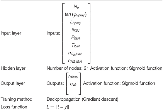
Table 3. Details of the neural network for prediction of parameters in the Wiebe function.
In the expansion model (EC ~ EVO), the pressure and temperature are predicted by polytropic change, just as in the compression model. The polytropic index in the expansion process is calculated as,
Finally, in the residual gas model (EVO ~ EVC), the temperature and composition at EVC are predicted. The pressure at EVC is assumed to be the same as the boost pressure and the temperature is predicted by polytopic change using the polytropic index in the expansion model.
The total quantity of substance at EVC is calculated using the ideal gas equation and the quantity of substance for each composition is calculated by assuming the same ratio at EVO. The temperature and composition are assumed to be the same as the temperature and composition of the residual gas.
Experiments
The DFE control model includes some coefficients that need to be adapted and the NN model also needs to be trained. To identify the DFE control model, experiments were carried out using a common inline 4-cylinder diesel engine (Figure 5). The engine specifications are shown in Table 4. This engine is equipped with the common rail injection system, high-pressure EGR, and variable geometry turbocharger. It is possible to operate this engine as a DFE, by providing an inlet for natural gas at the upstream of the intake pipe and controlling the natural gas flow rate with a mass flow controller. The in-cylinder pressure was measured by a pressure sensor and the average value of 200 cycles was used. Also, the exhaust gas composition was measured and the measurement time length was 10 s for each condition. Further, to change the operation condition, an ECU by-pass tool was used. The experimental conditions are shown in Table 5. These conditions realize multi-stage diesel injection, including early injection, in low load. The number of experiments would be enormous if the experiment had been conducted on all combinations, hence the experiment was conducted under 135 conditions using the design of experiments. Out of the 135 conditions, 120 conditions were used for model adaptation and the remaining 15 conditions were used for verification. By adapting the DFE control model using the experimental data, the DFE control model was able to predict combustion efficiency with good accuracy, Figure 6. Among the range where the experiment was done, Table 5, using this model it is possible to predict the combustion efficiency due to the changes in various operating conditions such as the diesel injection conditions, intake conditions, or engine speed. However, it might be difficult to predict accurately out of this range. This is because the model includes several statistical models, such as multiple regression analysis and neural network model.

Figure 5. Experiment setup for DFE combustion control model identification.
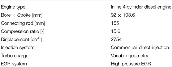
Table 4. The engine specifications for the DFE combustion control model.
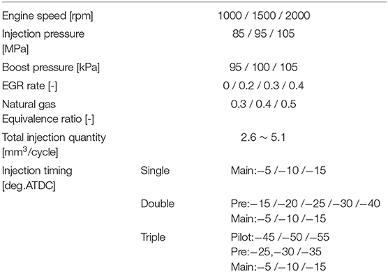
Table 5. Experiment condition for the DFE combustion control model identification.
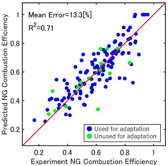
Figure 6. Prediction accuracy of the combustion efficiency.
DFE Control System
The purpose of the controller to be constructed in this research is to predict the proper diesel injection condition to maximize combustion efficiency. Since the DFE control model is a non-linear model, a non-linear optimal control using the gradient method was introduced. The diagram of the constructed controller in this research is shown in Figure 7. The inputs of this controller are uini (initial injection timing, quantity, and pressure) and x (engine speed, EGR rate, boost pressure, and equivalence ratio of natural gas). Also, the purpose of this controller is to maximize combustion efficiency, therefore the objective function was set, as shown in Equation (23). First, to obtain the gradient of the objective function against the injection conditions, a deviation u was given to the initial injection conditions uini, and the combustion efficiency was calculated for each case by the DFE control model. The gradient against the injection conditions is calculated using these calculated results, and the injection conditions are updated according to this gradient and renewal rate λ. The injection conditions were updated until the gradient was smaller than a constant α, and output the injection condition at the same time as the optimized injection condition. However, the injection conditions were updated in the range of the experiment done (see Table 5). Also, λ and α were set as a constant in this research.
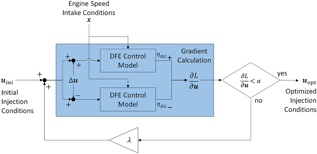
Figure 7. Controller diagram.
To evaluate this controller, the combustion efficiency was compared by experiments in 36 conditions against random combinations of operating conditions, after which the conditions of injection were changed to that which the controller outputted. When changing the injection condition, the engine speed and intake conditions were set to be the same. By changing the injection conditions to which the controller outputted, the combustion efficiency improved in all 36 conditions (see, Figure 8A).
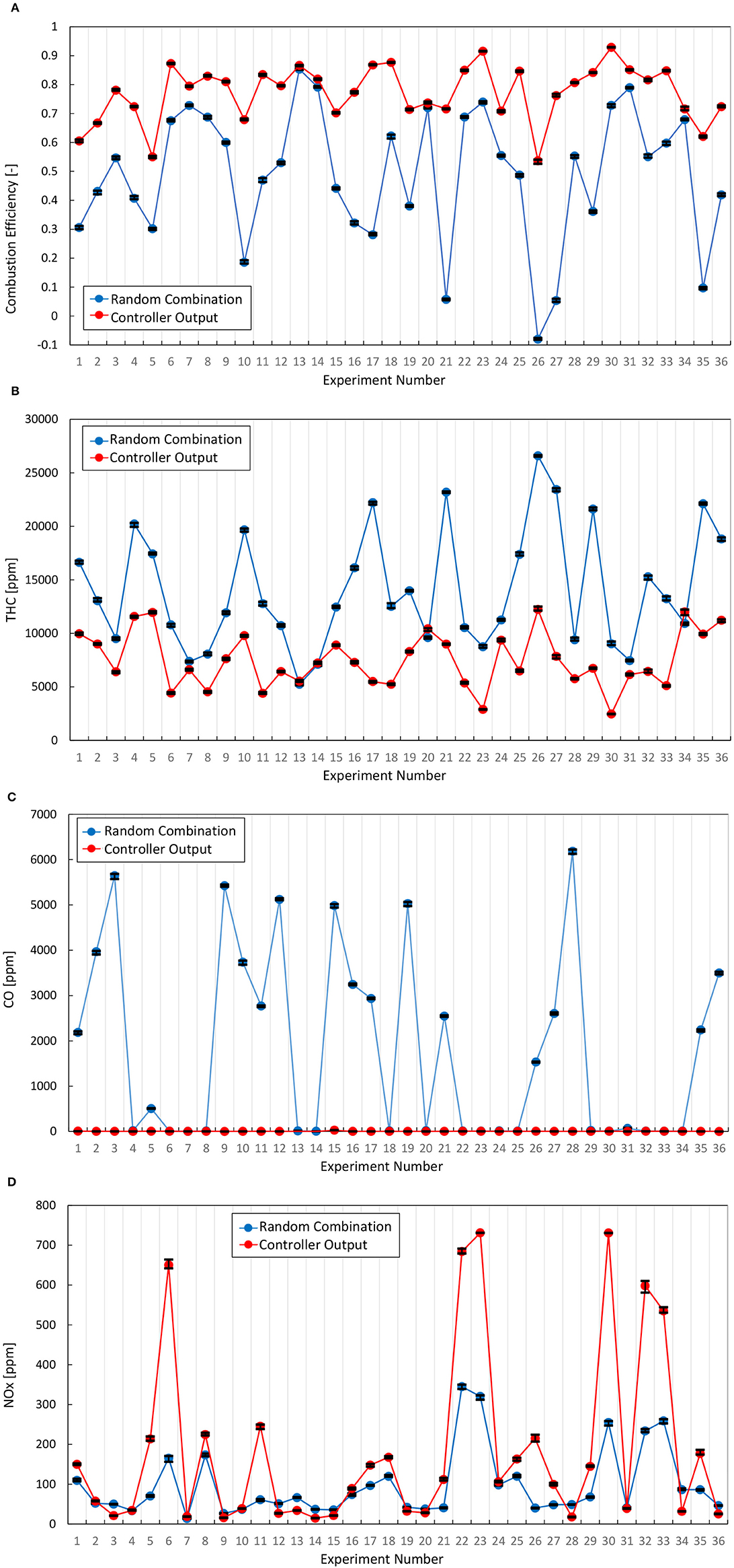
Figure 8. Comparison of combustion efficiency and emissions. (A) Combustion efficiency, (B) THC, (C) CO, (D) NOx.
Also, the change of the emission of CO and THC are shown in Figures 8B,C. Each plot represents the average value during the measurement at each condition and the error bar represents the maximum and minimum value. From Figure 8B, the emission of THC has decreased in most experiment numbers by the DFE controller. Also, from Figure 8C, the emission of CO decreased, especially when there was a lot. This controller changes the diesel injection conditions to maximize the combustion efficiency and this directly improves the emission of THC and CO. However, in some experiment numbers, the emission of THC slightly increased. In these numbers, the emission of CO decreased and the combustion efficiency improved overall. The reason why the emission of THC did not improve in these numbers is believed to be because the diesel injection conditions at the random combinations were already close to the conditions which maximize the combustion efficiency and the combustion efficiency was restricted by the intake conditions. As mentioned earlier, the controller changes only the diesel injection conditions, and the intake conditions, such as the EGR rate or the boost pressure, were set the same. As a further study, to design a controller that also considers the intake conditions is needed.
Furthermore, the emission of NOx was also measured and the NOx emission increased to a high level in some experiment numbers, Figure 8D. Just as with THC and CO, each plot represents the average value during the measurement at each condition and the error bar represents the maximum and minimum value. This research focused on maximizing the combustion efficiency and does not consider NOx emission for fuel injection conditions, but consideration of NOx emission is required even in DFE under a low load. Therefore, as a further study, in order to control for the NOx emission as high combustion efficiency, a prediction model of NOx emission from DFE is needed and optimization is required by coupling with the NOx emission model and the present combustion model.
Also, to confirm that the controller predicted the change of the combustion efficiency against the injection conditions, the experiment was conducted around the injection conditions outputted by the controller (see Figure 9). Also, the combustion efficiency predicted by the model is the parameter used to predict the heat release rate (Equation, 17), while combustion efficiency measured in the experiment is calculated from the unburned fuel concentration in the exhaust gas. Therefore, these two compared in Figure 9 do not match in absolute value, hence the issue now is whether the change trends are consistent. Regarding the injection pressure, quantity, and the main injection timing, the model predicted the trend of combustion efficiency in the real engine. On the other hand, regarding the pilot and pre-injection timing, the model was able to predict the maximum point among the range of the experiment done. However, the model could not predict the slight downward convex which the real engine showed. The constructed model in this research includes non-linear models such as the ignition timing model or the diesel spray model, but since the formula for ultimate prediction of the combustion efficiency (Equation 17) is a linear format, the model could not predict the non-linearity.
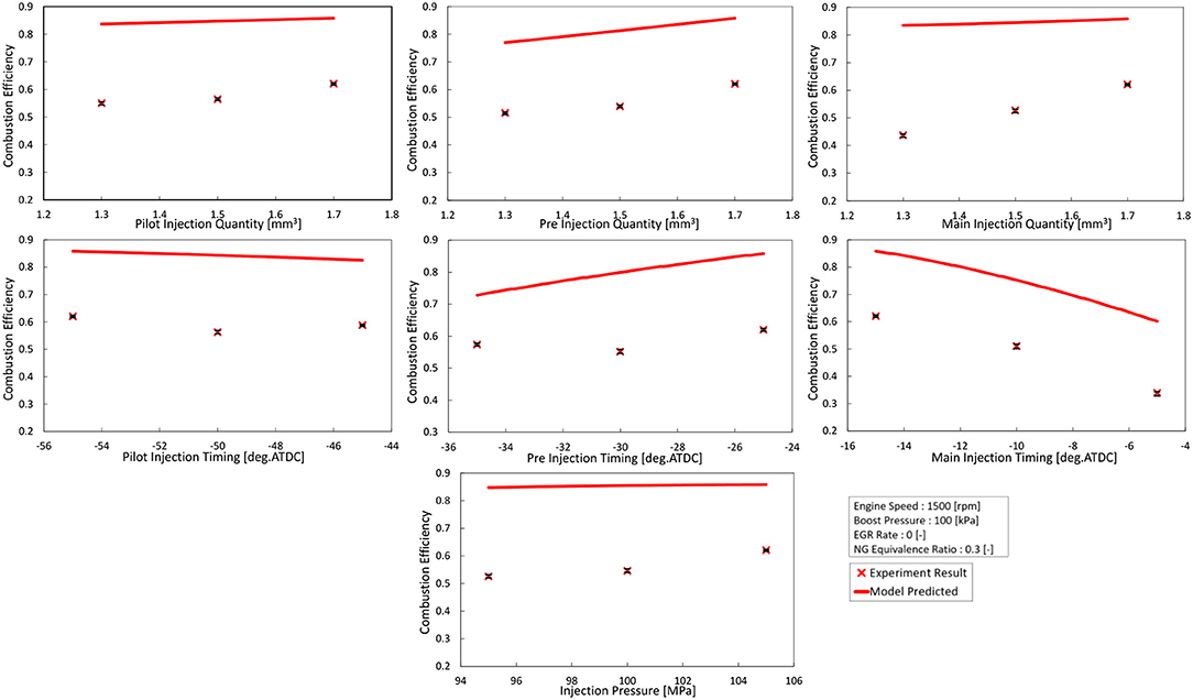
Figure 9. When the injection conditions were changed around the output of the controller.
The combustion efficiency increases monotonically with the injection quantity (Figure 9). Therefore, when the controller considers only the combustion efficiency (Equation 23), the injection quantity of diesel fuel increases. If the injection quantity increases, the combustion efficiency improves, but increasing the heat ratio of diesel fuel to natural gas is not desirable from the viewpoint of the effective use of natural gas, as it has a smaller environmental impact. Therefore, the objective function of Equation (23) was reconsidered to consider the combustion efficiency and the heat ratio of natural gas. The objective function was changed to,
where QNG is the input heat of natural gas and Qdiesel is the input heat of diesel fuel. When considering only the combustion efficiency (Equation 23), the combustion efficiency did improve against the random conditions, but the heat ratio of natural gas did not show a difference. However, by considering the heat ratio of natural gas (Equation 24), the points where the heat ratio of natural gas was low shifted toward the higher heat ratio of natural gas without the combustion efficiency becoming worse (Figure 10).
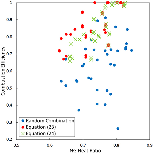
Figure 10. Relation between combustion efficiency and the heat ratio of natural gas.
Conclusion
In this research, a model-based control system was constructed for DFE using natural gas and diesel fuel, to maximize the combustion efficiency at low load by adjusting the diesel injection conditions. First, by the visualization experiment, it has been explained that the combustion efficiency improves when using a multi-stage diesel injection including early injection, since the ignition points increase. Also, a control model that predicts the combustion efficiency of the natural gas was constructed, assuming a multi-stage diesel injection at low load. Then, by using this control model, it was able to construct a controller that outputs the diesel injection condition to maximize the combustion efficiency of natural gas.
This research mainly focused on improving the low combustion efficiency under low loads in order to save fuel and reduce CO2. The issue of the low combustion efficiency must be solved first, hence this paper focused on the combustion efficiency. By improving combustion efficiency, the emission of HC and CO also improved since these substances are mostly caused by unburned natural gas. However, further study is required to correctly evaluate the benefit on the fuel and CO2 saving with the consideration of NOx emission, as NOx emission will give several constraints to injection conditions. In order to control NOx emission with high combustion efficiency, an NOx emission model is required, and the controller should be designed using the combined model of the combustion model and the NOx emission model.
Data Availability Statement
The datasets generated for this study are available on request to the corresponding author.
Author Contributions
YY managed whole of this study. HI carried out experiments, modeling, and analyzed data. YT and TS developed experimental apparatus and carried out experiments. All authors contributed to the article and approved the submitted version.
Conflict of Interest
YT and TS were employed by the company OSAKA GAS CO., LTD.
The remaining authors declare that the research was conducted in the absence of any commercial or financial relationships that could be construed as a potential conflict of interest.
References
Abdelaal, M. M., and Hegab, A. H. (2012). Combustion and emission characteristics of a natural gas-fueled diesel engine with EGR. Energy Convers. Manage. 64, 301–312. doi: 10.1016/j.enconman.2012.05.021
Aklouche, F. Z., Loubar, K., Bentebbiche, A., Awad, S., and Tazerout, M. (2018). Predictive model of the diesel engine operating in dual-fuel mode fueled with different gaseous fuels. Fuel 220, 599–606. doi: 10.1016/j.fuel.2018.02.053
Awad, S., Varuvel, E. G., Loubar, K., and Tazerout, M. (2013). Single zone combustion modeling of biodiesel from wastes in diesel engine. Fuel 106, 558–568. doi: 10.1016/j.fuel.2012.11.051
Carlucci, A. P., Colangelo, G., Ficarella, A., Laforgia, D., and Strafella, L. (2015). Improvements in dual-fuel biodiesel-producer gas combustion at low loads through pilot injection splitting. J. Energy Eng. 141, 1–8. doi: 10.1061/(ASCE)EY.1943-7897.0000231
Carlucci, A. P., Ficarella, A., and Laforgia, D. (2006). Control of the combustion behavior in a diesel engine using early injection and gas addition. Appl. Therm. Eng. 26, 2279–2286. doi: 10.1016/j.applthermaleng.2006.03.016
Ichihashi, H., Yamasaki, Y., and Kaneko, S. (2019). Combustion and emission characteristics of multiple fuel injections on a dual fuel engine (in Japanese). Trans. JSME 85:874. doi: 10.1299/transjsme.18-00363
Kojima, H., Yoshida, A., Tsujimura, T., Fujino, T., Kawakita, S., Kondo, W., et al. (2016). A strategy of intake gas control for diesel dual fuel engine with natural gas and diesel fuel (in Japanese). Trans. Soc. Autom. Eng. Jpn. 47, 889–894. doi: 10.11351/jsaeronbun.47.889
Krishnan, S. R., Srinivasan, K. K., and Raihan, M. S. (2016). The effect of injection parameters and boost pressure on diesel-propane dual fuel low temperature combustion in a single-cylinder research engine. Fuel 184, 490–502. doi: 10.1016/j.fuel.2016.07.042
Livengood, J. C., and Wu, P. C. (1995). Correlation of autoignition phenomena in internal combustion engines and rapid compression machines. Int. Sympos. Combust.5, 347–356.
Maroteaux, F., Saad, C., and Aubertin, F. (2015). Development and validation of double and single Wiebe function for multi-injection mode Diesel engine combustion modeling for hard-ware-in-the-loop applications. Energy Convers. Manage. 105, 630–641. doi: 10.1016/j.enconman.2015.08.024
Merker, G. P., Schwarz, C., Stiesch, G., and Otto, F. (2005). Simulating Combustion: Simulation of Combustion and Pollutant Formation for Engine-Development. Springer Science & Business Media.
Min, X., Wei, C., Zhi, L., Hongfei, Z., Tao, A., and Zhaokang, M. (2016). Pre-injection strategy for pilot diesel compression ignition natural gas engine. Appl. Energy 179, 1185–1193. doi: 10.1016/j.apenergy.2016.07.024
Papagiannakis, R. G., and Hountalas, D. T. (2004). Combustion and exhaust emission characteristics of a dual fuel compression ignition engine operated with pilot Diesel fuel and natural gas. Energy Convers. Manage. 45, 2971–2987. doi: 10.1016/j.enconman.2004.01.013
Ravi, N., Jungkunz, A. F., Roelle, M. J., and Gerdes, J. C. (2006). A physically based two-state model for controlling exhaust recompression hcci in gasoline engines. ASME IMECE 2006-15331, 483–492. doi: 10.1115/IMECE2006-15331
Reitz, R. D., and Bracco, F. B. (1979). “On the dependence of spray angle and other spray parameters on nozzle design and operating conditions,” in SAE Technical Paper (Detroit, MI). doi: 10.4271/790494
Takahashi, M., Yamasaki, Y., Kaneko, S., Fujii, S., Mizumoto, I., Hayashi, T., et al. (2019). “Model-based control system for a diesel engine,” in IFAC 9th AAC (Orléans), 23–27.
Vibe, I. I. (1970). Brennverlauf und Kreisprocess von Verbennungsmotoren. Berlin: VEB Verlag Technik.
Yamasaki, Y., Ikemura, R., Shimizu, F., and Kaneko, S. (2019a). Simple combustion model for a diesel engine with multiple fuel injections. Int. J. Eng. Res. 20, 167–180. doi: 10.1177/1468087417742764
Yamasaki, Y., Ikemura, R., Takahashi, M., Kaneko, S., and Uemichi, A. (2019b). Multiple-input multiple-output control of diesel combustion using a control-oriented model. Int. J. Eng. Res. 20, 1005–1016. doi: 10.1177/1468087418820739
Yang, B., and Zeng, K. (2018). Effects of natural gas injection timing and split pilot fuel injection strategy on the combustion performance and emissions in a dual-fuel engine fueled with diesel and natural gas. Energy Convers. Manage. 168, 162–169. doi: 10.1016/j.enconman.2018.04.091
Yasar, H., Soyhan, H. S., Walmsley, H., Head, B., and Sorusbay, C. (2008). Double-Wiebe function: an approach for single-zone HCCI engine modeling. Appl. Therm. Eng. 28, 1284–1290. doi: 10.1016/j.applthermaleng.2007.10.014
Yasuda, K., Yamasaki, Y., Kaneko, S., Nakamura, Y., Iida, N., and Hasegawa, R. (2016). Diesel combustion model for on-board application. Int. J. Eng. Res. 17, 748–765. doi: 10.1177/1468087415611331
Keywords: dual-fuel engines, natural gas, control model, model-based control, combustion efficiency
Citation: Ichihashi H, Yamasaki Y, Takashima Y and Sako T (2020) Model-Based Control for Dual-Fuel Engines. Front. Mech. Eng. 6:48. doi: 10.3389/fmech.2020.00048
Received: 13 March 2020; Accepted: 02 June 2020;
Published: 05 August 2020.
Edited by:
Masahiro Shioji, Kyoto University, JapanReviewed by:
Khanh Duc Cung, Southwest Research Institute (SwRI), United StatesEzio Mancaruso, National Research Council (CNR), Italy
Copyright © 2020 Ichihashi, Yamasaki, Takashima and Sako. This is an open-access article distributed under the terms of the Creative Commons Attribution License (CC BY). The use, distribution or reproduction in other forums is permitted, provided the original author(s) and the copyright owner(s) are credited and that the original publication in this journal is cited, in accordance with accepted academic practice. No use, distribution or reproduction is permitted which does not comply with these terms.
*Correspondence: Yudai Yamasaki, eXVkYWlfeUBmaXYudC51LXRva3lvLmFjLmpw