 Callen Fisher
 Alexander Blom
 Amir Patel
- Mechatronics Lab, Department of Electrical Engineering, University of Cape Town, Cape Town, South Africa
In nature animals are highly adapted to perform rapid maneuvers. However, these maneuvers have generally been avoided by robotics researchers due to the complex (and poorly-understood) dynamics they entail. To improve the agility of the current state-of-the-art robots, highly agile platforms need to be developed capable of performing these maneuvers. Due to the complexities involved, robotics researchers need to leverage trajectory optimization techniques to inspire and aid in designing and controlling these platforms. Presented here is the optimization-inspired design and testing of an agile bipedal robot called Baleka, which has specifically been designed for rapid acceleration and gait termination. By using the Vertical Agility metric (VA), experimental results show that Baleka is one of the most agile biped robots. Baleka achieved a vertical agility of 1.86 m/s (for the biped) and 1.82 m/s (for the monopod). When leaping with a single leg, Baleka achieved a vertical agility of 1.33 m/s, surpassing that of humans (0.89 m/s). These results indicate the power of using trajectory optimization methods to aid in the mechanical design process and prove Baleka's suitability for future rapid transient maneuver studies.
1. Introduction
Legged locomotion is by far the most optimal method for locomotion on land as it allows for the navigation on rugged, non-smooth terrain, along with agile rapid maneuvers. These agile maneuvers are paramount to survival in nature, be it hunting prey or evading predators. These maneuvers are performed almost effortlessly by animals yet we are nowhere near replicating these behaviors in robotic systems. These maneuvers (acceleration, braking, and turning) will be critical if our robots are 1 day to leave the safe confines of the laboratory.
Such transient motions are not well-understood, with many of the most well-known studies taking inspiration from nature to achieve high maneuverability, such as the MIT Cheetah (Ananthanarayanan et al., 2012; Park and Kim, 2014; Wensing et al., 2017). However, the optimal leg morphology of animals may not be optimal for the robotic equivalent due to robots not being constrained by the same factors. Animals comprise of compliant muscle tendon actuators whereas robots use rigid links and linear (pneumatics, linear motors) or rotary actuators (servo motors, torque motors) with some designers adding series or parallel elements such as springs and dampers (Hutter et al., 2012). Therefore, robots must be designed around the desired task, as the resulting dynamics of such different morphologies would greatly affect the achievable maneuverability. Thus, direct biomimicry may not always be suitable or optimal for rapid maneuvers of robots.
That being said, most roboticists are yet to investigate these complex, transient motions and are currently focused on steady-state locomotion with the aims of improving the top speed as well as the energy efficiency (Hubicki et al., 2018; Kashiri et al., 2018). However, there has been some research efforts into understanding the dynamics, control and design of robotic maneuverability. Various trajectory optimization studies have been employed to study the dynamics of rapid acceleration and braking (Hubicki et al., 2015, 2018; Fisher et al., 2019). There have also been efforts to study the unique mechanical and morphological requirements for agile robots (Semini et al., 2010; Blom and Patel, 2018). More recently, the Authors have conducted an investigation into how robots should accelerate and decelerate (Fisher et al., 2019), where it was shown that the energy optimal movement is to launch straight into the desired gait and avoid performing multiple intermediate gaits. These experiments were however performed in simulation, with the next steps aimed at validating these results on a physical platform. For this to occur, a novel highly agile platform needs to be developed.
There has been some recent interest in optimizing platforms for vertical agility (maximum hopping height multiplied by the frequency of the hops (Duperret et al., 2016; Haldane et al., 2016). It has also been suggested that having a high vertical agility is fundamental for rapid transient motions for bipedal robots, as the entire robot torso can lean forward and actuate with the legs as if it were a normal vertical jump (Blom, 2019). Thus, if a biped excels in vertical agility, it is a reasonable assumption that the robot would perform well in forward planar agility. The only limitation of the vertical agility test ultimately comes down to the friction at the foot which is unrelated to the power of the platform.
With that being said, what should the actuation topology look like for rapid maneuverability? There are numerous actuator schemes that have seen typical use in legged robotics, however the benefits of one typically results in a downfall of another. Furthermore, given the limited knowledge on the expected leg motions for rapid maneuvers, it is undesirable to select an actuation scheme that may inhibit certain movements. Compliance, such as serial elastic actuators (SEA's, Pratt and Williamson, 1995; Hutter et al., 2011; Hubicki et al., 2016), is mainly determined by the desired motion of a robot. However, given that rapid acceleration motions are not known and the degradation of control bandwidth, it is clear that all passive compliance should be avoided, using virtual compliance to actively modulate the elasticity on the fly.
To achieve Virtual Compliance, the actuators should have a high control bandwidth (Hutter et al., 2011; Hubicki et al., 2016; Park et al., 2017). Thus, geared motors are not suitable given the significant backlash as well as poor proprioceptive characteristics. A high mass-specific force output is highly desirable for rapid acceleration maneuvers, thus, Quasi Direct-Drive was selected, forgoing some of the advantages of direct drive such as reduced control bandwidth, improved robustness and improved proprioceptive sensitivity to gain a several fold increase in mass-specific torque output. However, a method to optimize parameters such as gear ratio and leg length ratio needs to be utilized. This was achieved in previous work (Blom and Patel, 2018) where the different leg designs were compared. Using trajectory optimization on a mathematical model of the biped, parameters such as gear ratio and leg length ratio were optimized for. The task being optimized was a long-time horizon task (where the robot had to start and end at rest and travel a fixed distance) in minimum time, which had a distinct acceleration, steady-state, and deceleration phase.
In this paper we build on the aforementioned simulation results and describe the development of the physical robotic platform, Baleka (meaning “To sprint” in Zulu), which is specifically designed for rapid acceleration studies. The methods used to inspire and design the robot are described in section 2, followed by the controller design in section 3. A number of experiments were performed on Baleka which are detailed in section 4, including the results. These are further discussed in section 5 with conclusions and future work presented in section 6.
2. Trajectory Optimization Inspired Mechanical Design
Previous research (Blom and Patel, 2018) selected a linkage morphology for the leg and optimized its design in simulation. There are several key properties that were focused on during the selection of the linkage morphology: the functional workspace, force transparency, force amplification, physical robustness and load sharing between actuators. There are two main leg morphologies seen in existing legged platforms, the Series-Articulate (used by MIT cheetah, Ananthanarayanan et al., 2012; Park and Kim, 2014; Wensing et al., 2017) and four-bar parallel linkage [used by Ghost Minitaur (Kenneally et al., 2016; De and Koditschek, 2018) and ATRIAS (Hubicki et al., 2016)]. The implications of using the four-bar mechanism with the chosen actuator scheme would result in an extremely large hip for the bipedal robot, with four motors and gearboxes located co-axially. To reduce the susceptibility of the robot to roll moments, a five-bar linkage was additionally investigated whereby the actuators are located adjacently, reducing the hip width by half.
The load distribution throughout the workspace for the parallel linkages (the four- and five-bar) was significantly better than that of the series articulate, which, in numerous locations, barely used one of the motors, shown in Figure 1. From the figure it can be seen that the load distribution for the parallel linkages was fairly evenly distributed with a symmetrical workspace, compared to the asymmetrical workspace for the series articulate linkage. The series articulate linkage often places a large load on one motor, while the other motor is hardly used, raising the torque requirements from each motor.
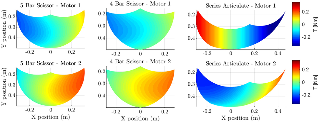
Figure 1. The load distribution characteristics of each linkage are shown. The four-bar and five-bar scissor linkages are seen to have a good load distribution for a 1N vertical force at the foot. However, the series articulate can be seen to have higher requirements from each motor, overall requiring higher rated torque motor to generate the 1N force. This figure also roughly depicts the shape of each linkages workspace.
Furthermore, by analyzing the singularity of the Jacobian, the best linkage ratio could be identified for each morphology [0.35 (L1/L2, Blom, 2019)] for the four- and five-bar linkage and 0.5 for the series articulate linkage) while simultaneously comparing the workspace, force amplification and proprioceptive sensitivity (more details can be found in Kenneally et al., 2016; Blom, 2019 and seen in Figure 2). From these results it was clear that the five-bar linkage mechanism was the optimal morphology with the best force amplification (minimize the maximum singular value) and proprioceptive sensitivity (maximize the minimum singular value), only falling short to the workspace of the four-bar linkage and can be seen in Figure 3.
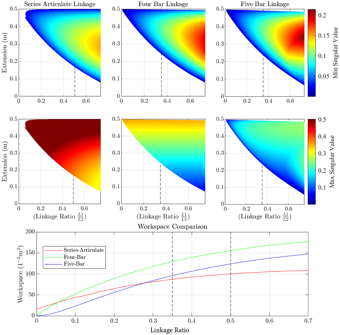
Figure 2. The singular values for each linkage mechanism (series articulate, four-bar and five-bar linkages) are shown. The minimum singular value should be maximized to make the end effector forces more visible to the motors. The maximum singular value should be minimized to improve the torque requirements at the motor to generate a force at the foot, resulting in a trade-off. The bottom graph also shows how the workspace changes with change in linkage ratio. From these graphs it is clear that the four- and five-bar mechanism offers the best performance in terms of visible forces on the motor and torque requirements to generate the required force. As soon as the linkage ratio is above 0.3, the four- and five-bar mechanisms also offers the best workspace capabilities. The dotted lines show the optimal ratio for each linkage system, with the four- and five-bar linkages being roughly the same at a linkage ratio of 0.35 and the series articulate being optimal at 0.5.
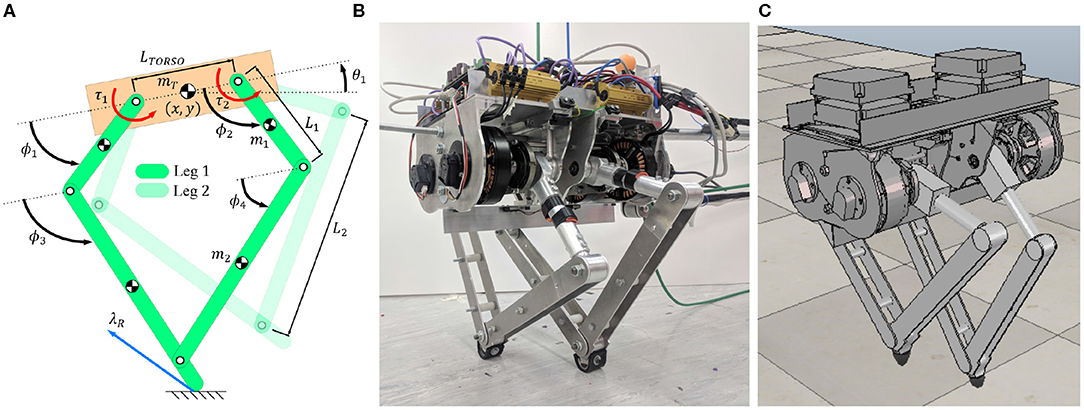
Figure 3. The mathematical model with all the generalized coordinates is shown on the left (A) with the physically built robot in the middle (B). On the right (C) is the V-Rep simulation of the robot with parameters imported from accurate SolidWorks models. For the mathematical model the position of the COM of the body is represented by x and y, with the pitch angle of the body represented by θ1 (an absolute angle). The femur's (top links of the leg) are represented by the relative angles ϕ1 and ϕ2 with respect to the body. The absolute angles are therefore ϕ1 + θ1 and ϕ2 + θ1 respectfully. The tibia's (bottom links of the leg) are represented by the relative angles ϕ3 and ϕ4 with respect to the body, with the absolute angle being ϕ3 + θ1 and ϕ4 + θ1 respectfully. The reason for this angle convention is due to it simplifying the constraints for the trajectory optimization methods.
In legged robotics, forward velocity can be achieved by having long legs and a low stride frequency or vice versa. There however are no formulas for determining the optimal leg length and resulting stride frequency. Determining the leg length becomes more complex when performing aperiodic maneuvers such as rapid acceleration and deceleration. Thus we leverage off trajectory optimization to determine an optimal nominal linkage length and gear ratio given the constraints of pre-bought motors (U12 T-Motors) and availability of gear boxes (a gear ratio of 3, 5, and 7 were available).
With a leg morphology chosen and the desired linkage ratio, the next challenge in the design process was to find a balance for the spatial-temporal gait characteristics (stride length and stride frequency). With short legs, high mass specific torque can be achieved but compromises on the duration that the force can be used while long legs allow for large strides but at very low frequencies. With complex maneuvers such as rapid acceleration this becomes practically impossible. To overcome this, trajectory optimization was used in a novel way to assist in the mechanical design process. This has been done in the past assisting in simpler scenarios (Ha et al., 2016; Spielberg et al., 2017). In this work we exploit trajectory optimization to its limits to identify both the best gear ratio (ng) and nominal leg length (L1 + L2) for a minimum time sprint, with the optimal link ratio (0.35). The task was to start and end at rest while traveling a fixed distance (Hubicki et al., 2015), which enforces a distinct acceleration, steady-state and deceleration phase. The task was optimized iteratively, adjusting parameters such as nominal leg length and gear ratio to determine the optimal parameters.
Below is an outline of the constraints and bounds of the trajectory optimization formulation, followed by the solving procedure and final mechanical design.
2.1. Constraints
A number of constraints were applied to guide the solver to find an optimal solution. These constraints included the following:
1. Direct Collocation: The trajectory optimization problem was discretized into N, 200, node points using direct collocation methods. The equations of motion (calculated using Euler-Lagrange methods) were discretized using Implicit-Euler integration:
where q are the generalized coordinates of the system at the ith node point. The generalized coordinates include the body position and angle, as well as the angle of each link. In order for the optimizer to minimize time, and handle the ground contacts, the time duration for each node, h, was allowed to vary as follows:
where hglobal was selected as 0.01 s (100Hz). This allowed the robot to take between 0.2 and 4 s to complete the long-time-horizon task.
Each leg of the biped resembled a closed kinematic chain, which created large complex equations of motions that struggled to result in a feasible trajectory. Therefore, each leg was modeled as two individual legs, with additional forces added to the connection point to enforce the closed kinematic chain (Blom, 2019). These forces were constrained to be equal but opposite, to ensure no net force is applied to the connection point. It is the task of the optimizer to solve these forces to ensure the leg connection remains together.
2. Contact-Implicit Methods: Due to the hybrid nature of legged robots (intermittent ground contact) as well as the complexity of the optimization task (contains rapid acceleration and deceleration maneuvers), a fixed contact order was not prescribed. Instead the optimizer was tasked with choosing the optimal contact order using Contact-Implicit Optimization methods (Posa et al., 2014). This method resulted in a number of complimentarity constraints (see Posa et al., 2014) Equations (8) to (18) that were solved using the penalty method:
The penalty was summed for each node point for each complimentarity constraint and added into the objective function to be minimized, and when solved αβ = 0. The contacts were modeled as inelastic collisions, and a friction cone (λ = 1) was enforced. This means that the contact can take one of two modes: Sticking or slipping. Slipping was modeled using a coulomb friction model (Posa et al., 2014).
3. Actuator Model: One of the design constraints of the project was to utilize U12 T-Motors. Therefore, an actuator model was implemented that restricted the available torque according to the velocity of the motor. This speed/torque model was a simple linear representation of the motor (Haberland and Kim, 2015) and is implemented as follows:
Where τmax and ωmax are the stall torque and no load speed characteristics of the motor. τ(i) and ω(i) are the applied torque and link velocity for the ith node. The torque and leg link velocity variables were further bounded to the parameters of the motor (τmax and ωmax, respectively).
4. Terminal Conditions: The task that the robot had to perform was the long-time-horizon task, that involved starting (enforced using bounds) and stopping (enforced using constraints) at rest, while traveling a fixed distance of 6m (enforced using constraints). The constraints were as follows:
where q are the generalized coordinates of the robot. The top constraint acts on all generalized coordinates except the horizontal position, X.
2.2. Bounds
Bounds were used to enforced the starting node, to ensure the robot started in a standing position, at rest (with zero velocity). This was implemented by setting the upper and lower bound to the desired value for the first node. Terminal conditions were enforced through constraints. Bounds were also placed on the leg links to ensure that the leg remained in its achievable workspace.
The remaining variables were bounded sufficiently high so as to not effect the solution space, but still restrict the search space (for example the bounds on the X position were set to [−1m, 7m], as the robot started at 0m and ran 6m).
2.3. Solving Procedure
The optimization problem was implemented in the General Algebraic Modeling System (GAMS (Corporation, 2015) using the IPOPT solver (Wachter and Biegler, 2006). For each leg length and gear ratio, 100 optimizations were performed, each initialized with a random seed (starting point) so as to not bias solutions and to ensure the search space was thoroughly searched. The nominal leg lengths ranged from 200 to 800mm in increments of 100mm with a gear ration of 3, 5, and 7 used.
The problem was posed as a minimum time problem, where the robot had to perform the long-time-horizon task, in the fastest time. A minimum time problem ensured that the robot performed a rapid acceleration and deceleration maneuver. The objective function took the following form:
where N is the number of node points, 200, and h(i) is the time duration for each node point. B is the scaling factor, 10 000, for the penalty. As the scaling factor is large, the optimizer first minimizes the penalty and then minimizes the time. J therefore represents the total time the robot took to complete the task once the penalty has been solved (reduced to zero).
2.4. Trajectory Optimization Inspired Final Design
Figure 4 shows a comparison of the sprint times for each of the long-time horizon tasks with the optimal time for the gear ratio of 3 occurring at a nominal leg length of 0.4m, for the gear ratio of 5 it occurred at a nominal length of 0.5m and for the gear ratio of 7 it occurred at 0.6m. These results were for the five-bar linkage with a linkage ratio of 0.35. The optimal result was with a gear ratio of 5, which was chosen for the Baleka robot. At the extremes of this graph, the longer links were heavier, decreasing the stride frequency, while the shorter links had less mass but required a higher stride frequency.
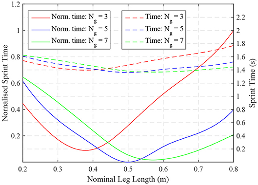
Figure 4. The normalized minimum time for the long-time horizon task are shown as a function of the nominal leg length (Ln = L1 + L2) and gear ratio (Ng) used in different models. It can be seen that large gear ratios improve performance with longer links. However, the optimal configurations of each gear ratio and leg length varies by roughly 0.5 s. From this a gear ratio of 5 with a nominal leg length of 0.5m was chosen for the Baleka robot.
Figure 5 shows a trajectory using the optimal gear ratio and linkage ratio (with a nominal length of 0.5m). The robot started at rest and accelerated (Phase 1) to steady-state (Phase 2, periodic motion). The robot then decelerated back to rest in Phase 3. The robot ran the trajectory of 6m (12 leg lengths) in 1.4 s.
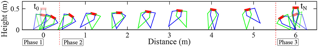
Figure 5. The most feasible trajectory solution of the bipedal model completing the long-time horizon task (start and end at rest while traveling a fixed distance). Phase 1 is the acceleration phase, Phase 2 is the steady-state (periodic motion) phase and Phase 3 is the deceleration phase of the motion.
From these results, the mechanical design of the robot was taken through the typical cyclic design process with several key focuses. Each leg of the biped was to be modular for possible future re-positioning, robust, inexpensive and have minimal friction and mass. Constraints on the mechanical design included using U12 T-motors which were readily available as well as using planetary gearbox supplied by Matex (available gear ratios included 3, 5, and 7 with the previous study revealing optimal ratio of 5). Common materials were used as far as possible given the limited budget available.
A prototype was built to take corrective action for any oversights. This concerned problems such as unexpected play and assembly issues. However, it was not a functioning prototype as it was created using 3D printed parts. A second iterative process was required where critical components in the final robot design underwent stress analyses and modified to meet a suitable factor of safety.
Furthermore, the ground reaction forces calculated from the trajectory optimization solutions from the previous research were used to estimate the stress the leg links would undergo, allowing a suitable safety factor to be chosen and minimizing weight. The platform weight was measured at 14.1kg with the weight of leg links making up only 13.32% of the body mass which is very similar to that of the MIT cheetah's leg (Park et al., 2014) which was roughly 10%.
The completed platform can be seen in Figure 3B with a list of the components presented in Table 1. A real-time operating system was implemented using Simulink Real-Time with an interface to the robot through Beckhoff Ethercat devices, with the operating system running at 500 Hz. A motion capture system (Pretorius and Boje, 2017) was located above the testing area. The system has sub-centimeter accuracy and was modified to determine the position and velocity of the robot. Furthermore, to determine the attitude of the robot body, an encoder was incorporated into the design of the boom. A method for detecting ground contacts was required to switch the controller through the different states. Two force sensors (ATI Axia 80 F/T Sensor) were purchased to enable this switching state to be detected. A ground force plate was then created with these two sensors. Furthermore, proprioceptive capabilities of the robot can be determined by measuring the ground reaction force at the end-effector. Once the platform was constructed, a mechanical boom was developed to constrain the motion in the sagittal plane. The boom was implemented as a four-bar mechanism (allowing vertical1 motion) that was free to pivot around the vertical axis (allowing horizontal motion). For the vertical agility tests, the boom was constrained to vertical motion and was not allowed to pivot.
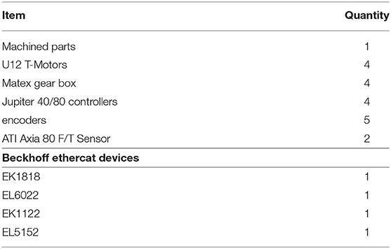
Table 1. Hardware components.
3. Controller Design
A virtual compliance controller (Kalouche, 2016) was designed to enable the five-bar mechanism leg to act as a spring loaded inverted pendulum (SLIP model, Blickhan, 1989; Geyer et al., 2006), with the radial length of the leg modeled as a prismatic spring. This was accomplished by first choosing some neutral length (ln), a spring constant Kl (N/m) and damping coefficient Cl (Ns/m) and then using the robotic legs radial position, rv, and velocity, ṙv, to generate the desired force, Fv:
where Fthrust is the commanded upwards force. Should virtual compliance be needed for leg angle, the desired torque, τv, was calculated in a similar manner to the prismatic spring:
where Kθv is the spring constant, θv is the angle of the virtual leg, θn is the selected neutral angle and Cθv is the damping coefficient. These controllers were first tested and tuned in simulation (the robot was emulated in V-REP with imported parameters form the SolidWorks model, see Figure 3C) and then tested on the physical platform, Figure 3B.
The anchor (the underlying object that fixes the SLIP model template to the physical platform) for the SLIP model was the five-bar linkage system shown in Figure 6. This anchor is used to transform the desired virtual forces and torques from the SLIP model into the joint space of the biped leg. The Jacobian, J, transpose of the five-bar linkage transforms the desired virtual leg force into the required motor torques as follows:
where the Jacobian matrix, J, is determined by the partial derivative of the forward kinematics equation, X = f(q), with respect to the generalized coordinates of the system, q, as follows:
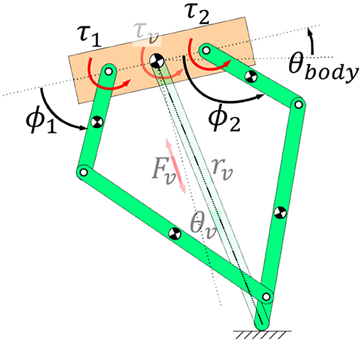
Figure 6. Image showing the five-bar linkage leg and how the virtual SLIP template was calculated with respect to the leg. See Figure 3 for a description of the generalized coordinates.
A sequential state-machine was also developed which enabled the robot to perform vertical hopping motions, which turned the virtual compliance controller on and off. For the hopping experiments, each leg was assigned one of 4 states of the state machine. Each leg is labeled as active or inactive. An inactive leg is pulled up to allow ground clearance when the active leg is preparing to land, getting compressed due to gravity and then pushing off to launch the robot into the air. The states include:
1. Compression: Virtual compliance controller implemented on the active leg while the leg is being compressed due to gravity, with Fthrust = 0.
2. Thrust: Virtual compliance controller implemented on the active leg with Fthrust commanded to launch robot into the air.
3. Flight wait: Pull the leg up while it is inactive.
4. Flight swing: Activate leg and move into landing position.
4. Experimental Tests
To test the robustness and agility of the platform, a number of experiments were conducted, and can be seen in Figure 7.
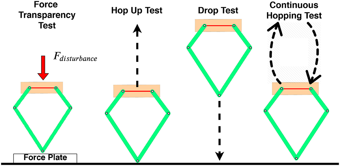
Figure 7. Image showing the four experiments performed on the robot. The first was a force transparency test, where an external force was applied to the robot which was standing on a force plate. The second test was a hop up test followed by a drop test. The fourth test was a continuous hopping test.
4.1. Force Transparency Test
Force transparency is highly desirable as it allows the platform to accurately perceive the ground reaction force (GRF) at the foot for an effective control strategy, while avoiding force sensors which increase the leg inertia. To measure the accuracy achievable, a single leg of the biped underwent several virtual compliance tests with external disturbances. The actual motor torques, τm, were calculated from the motor currents and multiplied by the inverse Jacobian, (JT)−1, to calculate the force at the end effector, Ffeedback. A three-axis force sensor (ATI Axia 80 F/T Sensor) was used below the foot in this experiment to determine the actual force exerted. Any discrepancies between these two readings would be due to either geometric errors, impedance, motor cogging torque or encoder initialization offsets.
To evaluate the force transparency of the linkage morphology and mechanical design, a range of stiffness and damping coefficients for the virtual spring model were used, with two of the results shown in Figure 8. The robot was initially dropped from an unspecified height, followed by an external disturbance. The Figure shows that the platform performed extremely well, with an averaged error of roughly 16%. It can be seen that the there is a minimal steady-state offset most probably due to the friction in the joints of the robotic platform. Furthermore, the force calculated from the motor torques does not capture the ground impact spikes acting as a low pass filter and filtering out force spikes up to 500N.
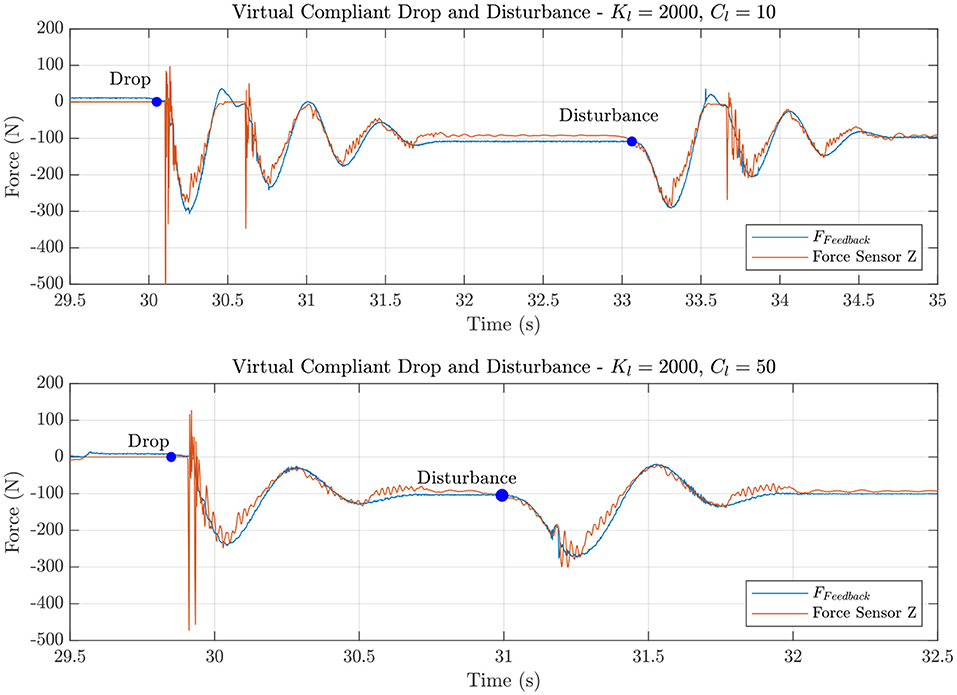
Figure 8. These graphs show the single leg module undergoing virtual compliance testing where an external disturbance was applied and the platform was raised and dropped (each test seen by the blue marker). The purpose of this test was to identify the force transparency of the system by comparing the force calculated from the torque feedback (11) to the six-axis ATI force torque sensor reading.
4.2. Jump and Drop Test
To ensure that the platform does not undergo any damage and is suitably robust, the jump test was investigated first. The maximum achievable height of the robot was then used in follow up drop tests to ensure that the platform can sustainably land from that height. To perform the jump test, Baleka was mounted on the boom arm and constrained to vertical motion only. To perform the jump tests, the standard virtual leg template was used and a foot force of Fthrust = 600N was commanded at the foot to saturate the motor drives (the limiting factor) for a significant portion of the launch. When the leg length of the template exceeds 0.45m, the radial leg damping was toggled to 150Ns/m to slow the foot down and avoid self impact. During these experiments the thrust force was increased, however, the linkage mechanism would interfere with itself (hitting the end stops), thus having to lower the thrust force and slow the foot velocity. In the monopod setup (biped jumping using one leg), the platform managed to jump 0.54m high, while hopping with both legs simultaneously achieved a height of 0.92m.
The drop tests are performed using the same set up but the virtual leg template was given a spring constant of 1, 500N/m with the neutral point at almost full extension and a damping constant of 120Ns/m for landing. This was stiff enough to ensure the robot does not bottom out (hit the hard stops on the limbs) while keeping the motor torques just below the actuation saturation limits. The leg was dropped at incrementing heights to ensure it could sustainably land. Ultimately the platform was able to land from the maximum hopping height.
4.3. Continuous Hopping and Vertical Agility Test
To ensure the platform was suitably robust, the leg was put through several continuous hopping experiments where the stance and aerial times were measured as well as the average height obtained. The test was also setup in a similar manner to the aforementioned experiments. Vertical Agility (Haldane et al., 2016) was the metric used to evaluate the agility of the biped robot, allowing the platform's performance to be compared to other known legged robots that have also been evaluated. Vertical Agility, VA, is defined as the vertical height a system can reach in a single jump, h, multiplied by the frequency of repeated hops, 1/(tstance + taerial). High leaping at high frequencies is considered to be more agile. Numerous robots and animals have had their vertical agility determined allowing the results gathered to be compared to judge the platforms performance.
It should be noted that all legged animals are limited to a ballistic trajectory and thus there was a point where hopping height and frequency can go no higher. Gravity, g, limits the rate at which a system can return to the ground, thus higher jumps inherently lower the hopping frequency.
Controllers were first tested in V-Rep to get initial gain values for the control strategy. These values were then used and tested on the physical robot. The robot can be seen jumping in Figure 9 with the associated forces and leg lengths. The single leg was able to jump to an average height of 0.81m. The vertical agility for the monopod was calculated to be 1.82 m/s. The biped was tested in a similar manner, where initially a single leg was held retracted. The platform was able to leap to 0.54m (in simulation it achieved 0.47m) with a vertical agility of 1.33 m/s. However, when the robot jumped with both legs simultaneously, a height of 0.92m was reached with a vertical agility of 1.86 m/s was achieved.
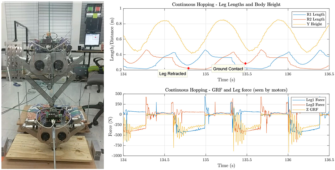
Figure 9. Baleka can be seen hopping on the left with the resultant ground reaction forces (proprioceptive and actual force) and leg lengths revealed on the graph on the right.
Beyond performance testing, it is a requirement for legged locomotion to be able to handle impacts continuously to ensure the suitability for rapid acceleration maneuvers and robustness. The continuous hopping tests were less aggressive than the vertical agility tests by reducing the thrust force and the resultant motion can be seen in Figure 9. During this motion the ground reaction force peaked at 900N, roughly 5.8 times the mass of the robot, similar to that of humans (Bobbert et al., 1992). The plot of the leg lengths and body height indicate that the platform's motion was consistent, suitable for legged locomotion control strategies.
5. Discussion
A novel bipedal robot was developed using trajectory optimization results to select parameters such as leg ratio and gear ratio. The results show that force sensing capabilities of the platform had an average error of 16%, which is in line with other platforms (MIT Cheetah and GOAT leg having an error of 5 and 19%, respectively (Kalouche, 2016; Wensing et al., 2017). This indicates that the leg mechanism and drive train selected was suitably designed for accurate proprioception and agile maneuvers. The error in force sensing was attributed to joint friction and motor cogging effects. Another advantage is that the impulsive spikes (up to 500N) were not captured.
Initial controllers were designed and tuned in a physics engine (V-Rep) before being tested on the physical platform. In simulation the robot achieved a continuous hopping height of 0.47m and on the platform it achieved a continuous hopping height of 0.54m. The difference between the results was attributed to how the ground reaction forces were handled in simulation (soft contact model) and how the boom was modeled (added mass and inertia to the robot). During these continuous hopping tests, the robot experienced a peak ground reaction force of 900N, which is roughly 5.8 times the mass of the robot.
The maximum jump height of the monopod setup was 0.54m while hopping with both legs resulted in a height of 0.92m. During the vertical agility tests, it was noted that the biped result of 1.86 m/s was higher than that of the monopod at 1.82 m/s. This increase was attributed to the reduced weight of the supporting boom that each leg had to carry, increasing the mass specific force of the robot.
The vertical agility of Baleka is compared against numerous well-known animals and robots in Figure 10 and Table 2. Leaping with only a single leg, Baleka's vertical agility of 1.33 m/s is greater than that of a human at 0.89 m/s. When leaping with both legs, the agility of the platform far exceeds all other robots with the exception of the GOAT leg with a vertical agility of 1.88 m/s, noting that it does not have to support the weight of a boom like Baleka does, showing that Baleka has a large payload capacity. All other metrics are compared in Table 2. In addition Baleka was able to leap the highest out off all existing robots (ignoring SALTO due to its extremely small body size of 0.25kg). This robot is the most agile biped making it suitable to perform rapid acceleration maneuvers and indicates that using optimization techniques for mechanical parameter selection is a viable part of the design process.

Figure 10. Image comparing the vertical agility of robotic platforms. The ballistic limit is also shown. The performance of Baleka can be seen to out perform the majority of other platforms and lies on the 2.2 m/s vertical velocity line.
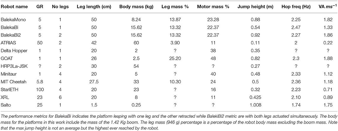
Table 2. Table comparing the different metrics (Park et al., 2014; Hubicki et al., 2016; Kalouche, 2016) of the robot developed in this work compared to other existing robots.
6. Conclusion and Future Work
In conclusion, trajectory optimization results were utilized to inspire the novel design of a bipedal robot called Baleka, which, in terms of vertical agility, out performs most of the current robotic platforms. These results are an indication that the platform is indeed suitable for testing agile transient motion controllers such as acceleration and deceleration. Future work will involve designing and testing these controllers on the platform and implementing the strategies described in Fisher et al. (2019) as well as investigating the effects of swinging arms (Wensing and Orin, 2013).
Data Availability Statement
The datasets generated for this study are available on request to the corresponding author.
Author Contributions
AP supervised and funded the research. CF developed the OS, advised on mechanical design, assisted in building and testing, and wrote the manuscript. AB designed and built the robot, designed all the controllers, and performed all the trajectory optimization. All authors contributed to the article and approved the submitted version.
Funding
This research was funded by the National Research Foundation (NRF) of South Africa under grant number: 117744.
Conflict of Interest
The authors declare that this study received funding from Beckhoff Automation and Ingenia Servo Drives. The funders were not involved in the study design, collection, analysis, interpretation of data, the writing of this article or the decision to submit it for publication.
Acknowledgments
The authors would like to thank Prof. Ed Boje and Dr. Reuben Govender for valuable insight into the mechanical design process. We would also like to thank Beckhoff Automation and Ingenia Servo Drives.
Supplementary Material
The Supplementary Material for this article can be found online at: https://www.youtube.com/watch?v=DtZ19lRYCyU, https://www.youtube.com/watch?v=-873JeUUT8A, and https://www.youtube.com/watch?v=EQG1dQV9zaw.
Footnotes
1. ^The motion is actually an arc, but due to the length of the boom it is considered as vertical motion.
References
Ananthanarayanan, A., Azadi, M., and Kim, S. (2012). Towards a bio-inspired leg design for high-speed running. Bioinspir. Biomimet. 7:046005. doi: 10.1088/1748-3182/7/4/046005
Blickhan, R. (1989). The spring mass model for running and hopping. J. Biomech. 22, 1217–1227. doi: 10.1016/0021-9290(89)90224-8
Blom, A. (2019). Design of a bipedal robot for rapid acceleration and braking manoeuvres (Master's thesis). University of Cape Town, Cape Town, South Africa.
Blom, A., and Patel, A. (2018). “Investigation of a bipedal platform for rapid acceleration and braking manoeuvres,” in IEEE International Conference on Robotics and Automation (ICRA) (Brisbane, QLD), 426–432.
Bobbert, M. F., Yeadon, M. R., and Nigg, B. M. (1992). Mechanical analysis of the landing phase in heel-toe running. J. Biomech. 25, 223–234. doi: 10.1016/0021-9290(92)90022-S
De, A., and Koditschek, D. (2018). Vertical hopper compositions for preflexive and feedback-stabilized quadrupedal bounding, pacing, pronking, and trotting. Int. J. Robot. Res. 37, 743–778. doi: 10.1177/0278364918779874
Duperret, J., Kenneally, G., Pusey, J., and Koditschek, D. (2016). “Towards a comparative measure of legged agility,” in Experimental Robotics: The 14th International Symposium on Experimental Robotics (Cham), 3–16.
Fisher, C., Hubicki, C., and Patel, A. (2019). Do intermediate gaits matter when rapidly accelerating? IEEE Robot. Automat. Lett. 4, 3418–3424. doi: 10.1109/LRA.2019.2927952
Geyer, H., Seyfarth, A., and Blickhan, R. (2006). Compliant leg behavior explains basic dynamics of walking and running. Proc. R. Soc. Biol. Sci. 273, 2861–2867. doi: 10.1098/rspb.2006.3637
Ha, S., Coros, S., Alspach, A., Kim, J., and Yamane, K. (2016). “Task-based limb optimization for legged robots,” in IEEE/RSJ International Conference on Intelligent Robots and Systems (IROS) (Daejeon), 2062–2068.
Haberland, M., and Kim, S. (2015). On extracting design principles from biology: II. case study-the effect of knee direction on bipedal robot running efficiency. Bioinspir. Biomimet. 10:016011. doi: 10.1088/1748-3190/10/1/016011
Haldane, D., Plecnik, M., Yim, J., and Fearing, R. (2016). Robotic vertical jumping agility via series-elastic power modulation. Sci. Robot. 1:10025797. doi: 10.1126/scirobotics.aag2048
Hubicki, C., Abate, A., Clary, P., Rezazadeh, S., Jones, M., Peekema, A., et al. (2018). Walking and running with passive compliance: lessons from engineering: a live demonstration of the atrias biped. IEEE Robot. Automat. Mag. 25, 23–39. doi: 10.1109/MRA.2017.2783922
Hubicki, C., Grimes, J., Jones, M., Renjewski, D., Spröwitz, A., Abate, A., et al. (2016). Atrias: design and validation of a tether-free 3d-capable spring-mass bipedal robot. Int. J. Robot. Res. 35, 1497–1521. doi: 10.1177/0278364916648388
Hubicki, C., Jones, M., Daley, M., and Hurst, J. (2015). “Do limit cycles matter in the long run? stable orbits and sliding-mass dynamics emerge in task-optimal locomotion,” in IEEE International Conference on Robotics and Automation (ICRA) (Washington, DC), 5113–5120.
Hutter, M., Gehring, C., Bloesch, M., Hoepflinger, M., Remy, C., and Siegwart, R. (2012). “Starleth: a compliant quadrupedal robot for fast, efficient, and versatile locomotion,” in World Scientific Adaptive Mobile Robotics (Baltimore, MD: Adaptive Mobile Robotics), 483–490
Hutter, M., Remy, C., Hoepflinger, M., and Siegwart, R. (2011). “Scarleth: design and control of a planar running robot,” in International Conference on Intelligent Robots and Systems (IROS) (San Francisco, CA), 562–567.
Kalouche, S. (2016). Design for 3d agility and virtual compliance using proprioceptive force control in dynamic legged robots (Master's thesis). Carnegie Mellon University, Pittsburgh, PA, United States.
Kashiri, N., Abate, A., Abram, S., Albu-Schaffer, A., Clary, P., Daley, M., et al. (2018). An overview on principles for energy efficient robot locomotion. Front. Robot. AI 5:129. doi: 10.3389/frobt.2018.00129
Kenneally, G., De, A., and Koditschek, D. (2016). Design principles for a family of direct-drive legged robots. IEEE Robot. Automat. Lett. 1, 900–907. doi: 10.1109/LRA.2016.2528294
Park, H., Chuah, M., and Kim, S. (2014). “Quadruped bounding control with variable duty cycle via vertical impulse scaling,” in International Conference on Intelligent Robots and Systems (IROS) (Chicago, IL), 3245–3252.
Park, H., and Kim, S. (2014). The mit cheetah, an electrically-powered quadrupedal robot for high-speed running. J. Robot. Soc. Japan 32, 323–328. doi: 10.7210/jrsj.32.323
Park, H., Wensing, P., and Kim, S. (2017). High-speed bounding with the mit cheetah 2: control design and experiments. Int. J. Robot. Res. 36, 167–192. doi: 10.1177/0278364917694244
Posa, M., Cantu, C., and Tedrake, R. (2014). A direct method for trajectory optimization of rigid bodies through contact. Int. J. Robot. Res. 33:69–81. doi: 10.1177/0278364913506757
Pratt, G., and Williamson, M. (1995). “Series elastic actuators,” in International Conference on Intelligent Robots and Systems (IROS) (Pittsburgh, PA), 399–406.
Pretorius, A., and Boje, E. (2017). Shutter delay estimation for a low-cost stand-alone visual tracking system. IFAC-PapersOnLine 50, 11441–11446. doi: 10.1016/j.ifacol.2017.08.1813
Semini, C., Tsagarakis, N., Guglielmino, E., and Caldwell, D. (2010). “Design and experimental evaluation of the hydraulically actuated prototype leg of the hyq robot,” in IEEE/RSJ International Conference on Intelligent Robots and Systems (Taipei).
Spielberg, A., Araki, B., Sung, C., Tedrake, R., and Rus, D. (2017). “Functional co-optimization of articulated robots,” in IEEE International Conference on Robotics and Automation (ICRA) (Singapore), 5035–5042.
Wachter, A., and Biegler, L. (2006). On the implementation of a primal-dual interior point filter line search algorithm for large-scale nonlinear programming. Math. Programm. 106:575–601. doi: 10.1007/s10107-004-0559-y
Wensing, P., and Orin, D. (2013). “Generation of dynamic humanoid behaviors through task space control with conic optimization,” in IEEE International Conference on Robotics and Automation (Karisruhe).
Keywords: legged robots, maneuverability, vertical agility, biped, Raibert control
Citation: Fisher C, Blom A and Patel A (2020) Baleka: A Bipedal Robot for Studying Rapid Maneuverability. Front. Mech. Eng. 6:54. doi: 10.3389/fmech.2020.00054
Received: 27 November 2019; Accepted: 10 June 2020;
Published: 21 July 2020.
Edited by:
Giovanni Gerardo Muscolo, Polytechnic University of Turin, ItalyReviewed by:
Mohsen Asadnia, Macquarie University, AustraliaCarlotta Mummolo, New Jersey Institute of Technology, United States
Carmine Tommaso Recchiuto, University of Genoa, Italy
Copyright © 2020 Fisher, Blom and Patel. This is an open-access article distributed under the terms of the Creative Commons Attribution License (CC BY). The use, distribution or reproduction in other forums is permitted, provided the original author(s) and the copyright owner(s) are credited and that the original publication in this journal is cited, in accordance with accepted academic practice. No use, distribution or reproduction is permitted which does not comply with these terms.
*Correspondence: Amir Patel, YS5wYXRlbEB1Y3QuYWMuemE=