 Roman Pohrt
- Department of System Dynamics and Friction Physics, Institute of Applied Mechanics, Technische Universität Berlin, Berlin, Germany
It is known that superposed movements can lower the friction felt at the macroscale. This is well documented for in-plane and normal translatory oscillations. Contact mechanics are a suitable approach to model this effect but so far have not gone beyond single-slider dynamics. In this study, we make use of 3D Boundary Elements Simulations to study the macroscopic friction reduction. This approach allows us to take into account also partial sliding of the contact zone. We first revisit the case of transversal in-plane translatory oscillations. Here, we argue that the behavior at small velocities can best be described when partial slip is indeed taken into account. Next, we investigate the frictional response of a Hertzian indenter when the lateral movement is superposed with a rotational bore movement. An analytical approximation is given for the steady state solution with constant angular velocity. The third case under investigation is an oscillating bore rotation. We present numerical results for the reduction of the macroscopic friction. In two limiting cases, an analytical prediction is given, following the lines used in the translatory case. For extremely large amplitudes, it is based on the idea that a rotational steady state is assumed at every instant. For small velocities we adapt our new approach including partial sliding. We find these predictions to be good but not perfect, slightly underestimating the reduction that rotational oscillations can provide.
Introduction
When frictional contacts are subjected to external oscillations, the friction felt at the macroscale is generally reduced. Since this constitutes a relatively simple way to control friction, the effect is used in countless manufacturing applications (Siegert and Ulmer, 2001a; Siegert and Ulmer, 2001b; Murakawa, 2001; Egashira and Mizutani, 2002; Ashida and Aoyama, 2007) as well as in noise control (Thomsen, 1999). On the negative side, it can lead to an error in measurements of the coefficient of friction (Kado et al., 2014).
The effect has been described experimentally in the middle of the last century (Fridman and Levesque, 1959; Pohlman and Lehfeldt, 1966; Godfrey, 1967; Lenkiewicz, 1969) but modeling was not attempted. In 2002, Storck (2002) investigated translatory in-plane oscillations experimentally and analytically. They argued that the interplay of forward friction and the superposed vibrations can be modeled using the perspective of contact mechanics with the simple Coulomb law of friction of a single slider. Kumar and Hutchings (2004) use a comparable modeling to interpret their experimental data. Tsai and Tseng (2005) employed the Dahl friction model to estimate the reduction for in-plane oscillations and found that rigid slider models overestimate the friction reduction. Teidelt, (2012) reported an impressive series of experimental data on the reduction for oscillations in the two in-place directions as well as the out-of-plane direction and interpreted the results using a model of rigid sliders. Starcevic and Filippov also worked on this dataset. They used the Method of Dimensionality Reduction to study static friction under the influence of in-plane parallel oscillations. Their setup consisted of two coupled parabolic sliders and included micro-slip (Starcevic and Filippov, 2012). The same method was used by Teidelt et al. (2012) to study the performance of Microdrive actuators. The simultaneous acting of normal and in-plane-parallel oscillation was studied by Popov and Li (2018) using an elastic slider model. The case of in-plane oscillation transversal to the macroscopic forward motion was modeled in a recent study by Benad et al., (2019). They used a coulomb-type frictional slider attached to a linear spring. In this work, results are given as a function of normalized input quantities and explicit dependencies are given for two limiting cases, corresponding to very low forward velocities (static friction) on the one hand and very large oscillation amplitudes on the other hand. Their work can be considered the starting point of the current paper. “Transverse Oscillations” section of the current paper will build on their results but will introduce explicit partial slip.
The setup under investigation is the following: We focus solely on superposed in-plane motion, leaving the normal contact unchanged. Unless stated otherwise, the indenter is a sphere with radius R, approximated by a parabola shape. It is compressed elastically against a non-deformable flat counterbody. The resulting contact zone and normal stresses are of the Hertzian type and are assumed to be unaffected by tangential stresses. The elastic sphere and the rigid counterbody interact locally with a constant coefficient of friction µ, such that the effective tangential stress inside the contact zone is always less or equal to the normal stress at that point. While the indentation depth in normal direction (z) is held constant, the sphere is subjected to controlled in-plane displacements. “Transverse Oscillations” section will start with a constant velocity in forward (x) direction and harmonic oscillation in y-direction. In “Continuous Rotation (Bore)” section, the sphere will also move with constant velocity but will also rotate (bore) around its central z-axis at constant angular velocity. “Oscillating Rotation (Bore)” section will cover the case of oscillatory bore rotation. In all cases, the macroscopic forward friction will be decreased. The greatest reduction is generally associated with larger amplitude, frequency or velocity, respectively, of the superposed motion.
Transverse Oscillations
The case of transverse oscillations consists of a frictional indenter which is moved with constant velocity in x-direction while its position in y-direction is given by a sine-function
The simplest approach is to assume that Eq. 1 describe not only the macroscopic motion of the indenter but also the exact motion of the contact spot. This approach neglects the lateral elasticity of the indenter. In contrast, the model of Benad et al. (2019) consists of a single slider but connected to the coordinates given in Eq. 1 by a linear spring. They showed that the stiffness has a considerable influence on the system behavior, in particular for small oscillation amplitudes. We agree with this assessment. Because the system is quasistatic, it makes sense to formulate in problem in a way that eliminates the time. Similar to Benad et al. (2019), we employ a set of two dimensionless variables for such system including elasticity. The amplitude of the oscillation is described as
where
The forward speed is normalized with respect to the speed of the oscillation and is expressed as the dimensionless variable.
The definitions
The dependent variable is the apparent coefficient of friction
Here
Results
Figure 1 shows a typical evolution of the resistive tangential force in x-direction. Such curves were obtained for a variety of combinations for parameters
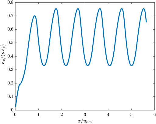
FIGURE 1. Dependency of the normalized tangential force on the displacement when transverse oscillations are applied. Here
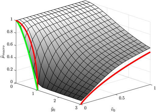
FIGURE 2. Dependency of the macroscopic coefficient of friction on the dimensionless velocity and oscillation amplitude for transversal oscillations. The smallest value of
Limiting Solution for Large Oscillation Amplitudes
An estimate for the apparent coefficient of friction at large oscillation amplitudes is given as
In the range covered in this current work, we find the same as (Benad et al., 2019): We basically confirm (6) and find it slightly overestimates the reduction in
Limiting Solution for Small Driving Velocities
The limit of small driving velocities can be considered the case of static friction. From a macroscopic point of view, this describes simply the value of the tangential force below which the indenter does not advance. Looking at the situation within an oscillation cycle, the limit translates into the requirement that at least during one infinitesimal instant of the cycle, a forward motion is possible.
In the elastic-single-slider model of (Benad et al., 2019), these instants coincide with the extremal values of the oscillations and a value for the tangential force can be associated. For
This solution is applicable for
Our numerical simulations show that Eq. 7 overestimates the macroscopic friction. In other words, the reduction resulting from the oscillation is underestimated. Here we’d like to argue that this due to the exclusion of partial slip in the model. Partial slip does not occur in a single slider element but requires a finite contact zone and distribution of normal stress.
For a Hertzian indenter in the absence of a forward motion, the oscillation with amplitude
where a is the contact radius. From this state, what condition must be met in order to achieve a forward motion? Since
Here p(r) is the distribution of normal contact stress. In the particular case of a Hertzian stress distribution, Eq. 9 reduces to
Furthermore in the particular case of translatory oscillations using Eq. 8 it reduces to
which is also plotted in Figure 2 and coincides much better with direct simulation results. Thus we see reason that unless the result is zero or one,
Continuous Rotation (Bore)
We now investigate a rotationally symmetric indenter which is rotated around the z-axis while sliding in the x-y-plane.
Since the problem is quasistatic, it can be reduced to a single system parameter and dimensionless time
In this configuration, the instantaneous center of rotation in the undeformed remote parts of the body is situated at
See Figure 3A. The steady state can be analyzed using the following simplifications.
• The velocities of all spots on the surface are assumed to be the same as their corresponding spots in the remote body
• For the calculation of frictional torque, surface stresses are assumed to act at the undeformed spot.
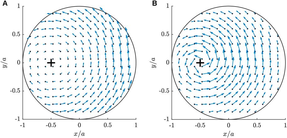
FIGURE 3. Hertzian indenter slipped in positive y-direction and rotated. Normalized forward speed
In particular, the above simplifications are valid for small µ. The amplitudes of the frictional stresses τ are given by
See Figure 3B for an example. The resulting tangential forces and torque can then be calculated as
wherein
The additional rotational movement eases the forward movement and effectively reduces the apparent coefficient of friction. Vice versa, the forward motion eases the rotation. Therefore, the required torque Mz also depends on
where Mz,0 is the steady state torque at zero forward velocity.
For a Hertzian Indenter the dependencies of Eqs 21 and 22 on
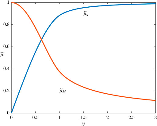
FIGURE 4. Theoretical prediction of the dependency of the macroscopic coefficient of friction on the dimensionless velocity for added continuous rotational (bore) movement to a Hertzian Indenter according to Eqs 21 and 22. The frictional resistances on both the forward motion and on the rotational torque are reduced.
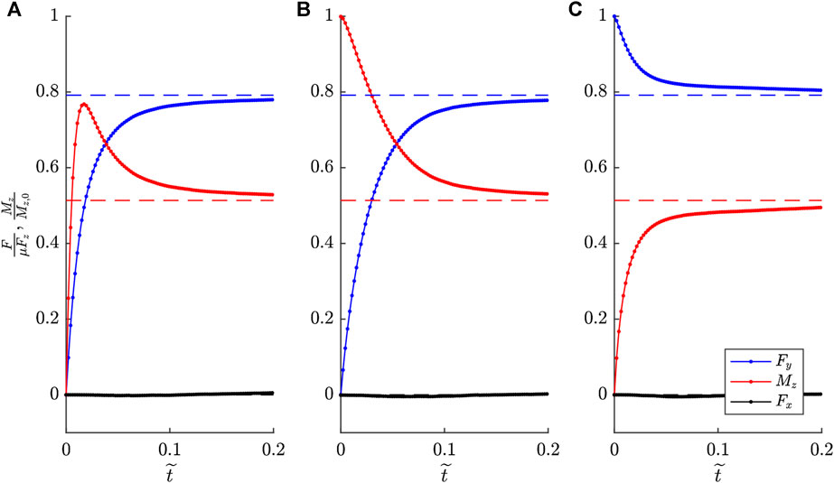
FIGURE 5. Coefficient of friction regarding Forces and torque of a Hertzian Indenter which is displaced and rotated simultaneously at
Interestingly, our simulations never showed zones of stick when the steady state was reached, even when instantaneous center of rotation is located inside the contact region.
Oscillating Rotation (Bore)
In this section, we will set a continuous forward motion and the additional bore rotation will be oscillating. Let us impose a displacement of the indenter according to
Some normalization is again required for the oscillation amplitude. In “Transverse Oscillations” section, it was divided by the maximum tangential deflection before the start of macroscopic slip, which is when the inner stick region fully vanishes. In the case of pure rotation of a Hertzian indenter however, there is no such maximum angle at which the stick region vanishes. According to Lubkin (1951) (indexed “lk”) (Popov, 2019), the stick radius c and the torsion angle φ are related as
where we introduced
With the complete elliptical integrals of the first and second kind
Indeed Eq. 24 tends to infinity for small c, meaning that the very center of the contact will always be in stick state. Normalization of the rotational amplitude will be instead be done with respect to the angle necessary to achieve a stick radius of
The normalization of the forward velocity is done with respect to the maximum speed of the contact zone edge at r = a
With these definitions, simulations and evaluation can be done in analogy to “Transverse Oscillations” section.
Results
Figure 6 shows the results of
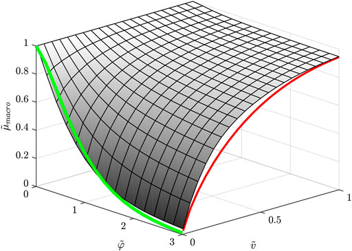
FIGURE 6. Dependency of the macroscopic coefficient of friction (forward) on the dimensionless velocity and oscillation amplitude for bore oscillations acting on a Hertzian Indenter. The smallest value of
Limiting Solution for Large Oscillation Amplitudes
For the limiting case of large amplitudes, a similar expression to Eq. 6 can be found, when it is assumed that the contact is always in a rotational-transversal steady state such as “Continuous Rotation (Bore)” section has introduced. Then, the results found in Eq. 21 can be averaged over one period with momentary values of
This finding is shown in Figure 6 with the red line. Please note the resemblance to Eq. 6 in Figure 2.
Limiting Solution for Small Driving Velocities
Following the approach laid out in “Limiting Solution for Small Driving Velocities,” it is possible to formulate an approximation for the static friction in the limit of
In a situation without forward motion, the rotational oscillation will give rise to a zone of constant stick. The oscillation amplitude
which we can now write in normalized form, introducing
This is a monotonous dependency with
We can then use this stick radius with Eq. 10 to find
Which is shown in Figure 6 with the green line. It can be seen that Eq. 33 constitutes a reasonably good prediction of static friction, but not an exact one. It appears to accurately predict the static friction very well for
This means that the forward force does not need to overcome the entire normal stress inside the oscillatory stick zone multiplied with
Conclusions
In this paper, we investigate friction under the influence of superposed motion using explicit contact mechanics. In all cases, the superposed motion reduces friction. The stronger the motion (faster, higher amplitude) the greater the reduction. Under the influence of any given superposed motion, the forward friction increases with the forward velocity, stabilizing the frictional system.
Based on the findings presented here for transversal oscillations, the spring model given in Benad et al. (2019) provides satisfactory results, except for very small forward velocities, so-to-speak for static friction when the oscillations provoke some partial slip, which should be taken into account. We postulate that in order to start a forward motion, only the friction inside this stick region must be overcome.
For friction under the influence of additional continuous bore movement, an approximation for the steady state is identified and given in “Continuous Rotation (Bore)” section. Both the friction opposing forward motion and opposing the rotation are reduced.
When the bore movement oscillates, a reduction of the macroscopic forward friction is again found and the dependency on forward velocity and oscillation amplitude resembles the transversal case (Compare Figures 2, 6). Here, two limiting cases are again identified and analyzed. At large amplitudes, assuming steady state in every instant leads to a good approximation. For small velocities near static friction, a new estimate with good agreement is suggested. It is again based on the stick zone caused by the oscillations alone. However, simulations show that the reduction of forward friction is even greater than predicted, hinting to a more elaborate mechanism.
Rotational bore oscillations are a promising way to control static friction or micro-propulsion due to two favorable properties over transversal oscillations. First,
Method
We employ the Boundary Elements Method for contact problems (Pohrt and Li, 2014). The normal contact is solved following standard procedures. Interaction of normal and in-plane deformations are not considered. Interactions between the two in-plane directions are considered. For the tangential contact, an iterative scheme is employed that ensures each point satisfies the following conditions in each time step.
• Tangential stress is below the frictional threshold
• Tangential stress
where τ is the tangential stress, having x and y components, p is the local pressure and
Data Availability Statement
The raw data supporting the conclusions of this article will be made available by the authors, without undue reservation.
Author Contributions
RP developed the BEM code, performed the simulations and created the text and figures.
Conflict of Interest
The author declares that the research was conducted in the absence of any commercial or financial relationships that could be construed as a potential conflict of interest.
Funding
This research was funded by regular financing of researchers at Technische Universität Berlin.
Acknowledgments
Discussions with colleagues from TU Berlin were helpful in efforts of the author.
References
Ashida, Y., and Aoyama, H. (2007). Press forming using ultrasonic vibration. J. Mater. Process. Technol. 187–188, 118–122. doi:10.1016/j.jmatprotec.2006.11.174
Benad, J., Nakano, K., Popov, V. L., and Popov, M. (2019). Active control of friction by transverse oscillations. Friction 7 (1), 74–85. doi:10.1007/s40544-018-0202-1
Egashira, K., Mizutani, K., and Nagao, T. (2002).Ultrasonic vibration drilling of microholes in glass. CIRP Ann. 51 (1), 339–342. doi:10.1016/S0007-8506(07)61531-5
Fridman, H. D., and Levesque, P. (1959). Reduction of static friction by sonic vibrations. J. Appl. Phys. 30 (10), 1572–1575. doi:10.1063/1.1735002
Godfrey, D. (1967). Vibration reduces metal to metal contact and causes an apparent reduction in friction. Tribol. Trans. 10, 183–192. doi:10.1080/05698196708972178
Kado, N., Tadokoro, C., and Nakano, K. (2014). Kinetic friction coefficient measured in tribotesting: influence of frictional vibration. Tribol. Online. 9 (2), 63–70. doi:10.2474/trol.9.63
Kumar, V. C., and Hutchings, I. M. (2004). Reduction of the sliding friction of metals by the application of longitudinal or transverse ultrasonic vibration. Tribol. Int. 37 (10), 833–840. doi:10.1016/j.triboint.2004.05.003
Lenkiewicz, W., (1969). The sliding friction process: effect of external vibrations. Wear 13, 99–108. doi:10.1016/0043-1648(69)90505-5
Murakawa, M. (2001). The utility of radially and ultrasonically vibrated dies in the wire drawing process. J. Mater. Process. Technol. 113 (1–3), 81–86. doi:10.1016/S0924-0136(01)00635-5
Pohlman, R., and Lehfeldt, E. (1966). Influence of ultrasonic vibration on metallic friction. Ultrasonics 4 (4), 178–185. doi:10.1016/0041-624X(66)90244-7
Pohrt, R., and Li, Q. (2014). Complete boundary element formulation for normal and tangential contact problems. Phys. Mesomech. 17 (4), 334–340. doi:10.1134/S1029959914040109
Popov, M., and Li, Q. (2018). Multimode active control of friction, dynamic ratchets and actuators. Phys. Mesomech. 21 (1), 24–31. doi:10.1134/s1029959918010046
Popov, V. L., Heß, M., and Willert, E. (2019). Handbook of contact mechanics. Exact solutions of axisymmetric contact problems. 1st Edn. Berlin: Springer‐Verlag, 347.
Siegert, K., and Ulmer, J. (2001a). Influencing the friction in metal forming process by superimposing ultrasonic waves. CIRP Ann. 50 (1), 195–200. doi:10.1016/S0007-8506(07)62103-9
Siegert, K., and Ulmer, J. (2001b). Superimposing ultrasonic waves on the dies in tube and wire drawing. J. Eng. Mater. Technol. 123 (4), 517–523. doi:10.1115/1.1397779
Starcevic, J., and Filippov, A. E. (2012). Simulation of the influence of ultrasonic in-plane oscillations on dry friction accounting for stick and creep. Phys. Mesomech. Mesomech. 15 (5–6), 330–332. doi:10.1134/S1029959912030150
Storck, H. (2002). The effect of friction reduction in presence of ultrasonic vibrations and its relevance to travelling wave ultrasonic motors. Ultrasonics 40, 1–8. doi:10.1016/s0041-624x(02)00126-9
Teidelt, E. (2012). Influence of ultrasonic oscillation on static and sliding friction, Tribol. Lett. 48, 51–62. doi:10.1007/s11249-012-9937-4
Teidelt, E., Willert, E., Filippov, A. E., and Popov, V. L. (2012). Modeling of the dynamic contact in stick-slip microdrives using the method of reduction of dimensionality. Phys. Mesomech. 15 (5–6), 287–292. doi:10.1134/S1029959912030071
Thomsen, J. (1999). Using fast vibrations to quench friction-induces oscillations. J. Sound Vib. 228, 1079–1102. doi:10.1006/jsvi.1999.2460
Keywords: friction, vibrations, microslip, fretting, shakedown
Citation: Pohrt R (2020) Friction Influenced by Vibrations: A Refined Contact-Mechanics View on Lateral and Rotational Oscillations. Front. Mech. Eng. 6:566440. doi: 10.3389/fmech.2020.566440
Received: 28 May 2020; Accepted: 14 September 2020;
Published: 05 October 2020.
Edited by:
Marco Paggi, IMT School for Advanced Studies Lucca, ItalyReviewed by:
Carmine Putignano, Politecnico di Bari, ItalyKen Nakano, Yokohama National University, Japan
Copyright © 2020 Pohrt. This is an open-access article distributed under the terms of the Creative Commons Attribution License (CC BY). The use, distribution or reproduction in other forums is permitted, provided the original author(s) and the copyright owner(s) are credited and that the original publication in this journal is cited, in accordance with accepted academic practice. No use, distribution or reproduction is permitted which does not comply with these terms.
*Correspondence: Roman Pohrt, cm9tYW4ucG9ocnRAdHUtYmVybGluLmRl