 Michael Antivachis1
 Christof Zwyssig
 Dominik Bortis
- 1Power Electronic Systems Laboratory, ETH Zurich, Zurich, Switzerland
- 2Celeroton AG, Volketswil, Switzerland
Fuel cell technology is continuously gaining ground in E-mobility applications. Fuel cells require a constant supply of pressurized air, for which high-speed turbo compressors with air bearings are an optimal choice to reduce size, guarantee oil-free operation required for the lifetime of the fuel cell, and increase efficiency. However, the inverter driving the electric motor of the turbo compressor does not scale down with increasing speed; therefore, other technology advances are required to achieve an overall compressor system with low weight. New power electronic topologies (double-bridge voltage sources inverter), cutting edge power semiconductor technology (gallium nitride), and multiobjective optimization techniques allow reducing the inverter size, increasing inverter efficiency, and improving the output current quality and in return lowering the losses in the electric motor. This enables the electrical, mechanical, and thermal integration of the inverter into the compressor housing of very high-speed and compact turbo compressors, thereby reducing the size and weight of the overall compressor system by a factor of two. Furthermore, a turbo compressor with an integrated inverter reduces complexity and cost for operators with savings in casing, cables, coolant piping, and connectors and reduces EMI noise by shielding the high-frequency motor currents with one housing. Beside its main application for fuel cell air supply, the advantages gained by an integrated inverter can also be used in other boosting and air handling applications such as advanced air and exhaust handling in combustion engines. The proposed integration concept is verified with a 280,000 rpm, 1 kW turbo compressor, targeted for the Balance of Plant (BoP) of a 5–15 kW fuel cell. The experimental results show that the temperature limits on the power electronics parts can be kept below the limit of 90 °C up to a coolant temperature of 55 °C, and beside the advantage of lower cabling effort, the efficiency of the compressor system (turbo compressor and integrated inverter) is increased by 5.5% compared to a turbo compressor without an integrated inverter.
Introduction
With the goal of attaining sustainable, secure, and competitive energy sources for transportation while combating climate change, there have been increased research activities into fuel cells. Beside propulsion systems for vehicles, there are further application areas for fuel cells, such as stationary combined-heat-and-power generation or auxiliary power supplies in aircraft and trucks. All fuel cells require a constant supply of pressurized air, which is provided by an air compressor system (Blunier and Miraous 2010; Fröhlich, 2019). Turbo compressors, also denoted as centrifugal compressors, are ideally suited for mobile fuel cell systems for cars, light commercial vehicles, air- and aerospace, port and airport vehicles, trucks, and rail applications thanks to their high power density, oil-free operation (in case of air bearings), low-pressure ripple, and low acoustic noise. In addition, turbo compressors have a high reliability, a long lifetime, and a high efficiency (Celeroton, 2016).
According to fundamental scaling laws, a higher rotational speed results in a higher power density of turbo compressors; i.e., the power density increases approximately proportional to the speed. This can be shown with similarity rules for scaling the aerodynamic part of the compressors (Casey et al., 2013) and scaling rules of the electric motor (Zwyssig et al., 2009). However, the power density of the power and control electronics, required to drive the motors of the compressors, is independent of the rotational speed, with rather a tendency toward lower power density at a higher rotational speed of the motor/compressor due to increased complexity and losses at high-speed operation (Zwyssig et al., 2009).
In the case of low-speed compressors, these scaling laws result in a comparably small power and control electronics volume, i.e., small inverters (in case of dc supply such as for fuel cell and battery-operated applications); hence, the compressor dominates the overall system volume. However, for high-speed turbo compressors, the inverter size becomes comparable to the compressor size or even exceeds it. The large volume of the inverter is acceptable for stationary applications where the inverter is placed separately in a cabinet, but it is a drawback for mobile applications, where a large inverter size reduces one of the main benefits of high-speed operation: the ultracompact size and small weight. In other words, most mobile fuel cell applications require an air compressor with minimum overall system weight and size including the inverter (Blunier and Miraous, 2010; Zhao et al., 2012).
Research and development activities in high-speed turbo compressors usually focus on the turbo compressor only, while the total compressor system including the inverter is neglected. On the other hand, research on the inverter side mainly focuses on the control of high-speed drives and not on the high power density and/or high efficiency of variable-speed drive systems (Taniguchi and Okumura, 1993; Kim and Youn, 2002; Zwyssig et al., 2007; Zwyssig et al., 2009). Therefore, this paper presents a novel fuel cell air compressor with the lowest overall system weight and size. This is achieved with three main technology bricks:
Employment of high-speed motor and centrifugal turbo compressor technology, which profits from the scaling laws of aerodynamics and motor design (Zwyssig et al., 2009; Casey et al., 2013).
A dedicated power electronics inverter topology, cutting edge semiconductor technology, and multiobjective design optimization techniques. These have been described in detail in (Antivachis, 2020), and the important aspects are summarized in Inverter Topology and Optimization.
Mechanical, electrical, and thermal integration of the power electronics into the compressor housing as described in detail in Compressor Design and Integration.
The paper first gives an overview of the underlying fuel cell system in Fuel Cells Systems. Afterward, a comprehensive analysis of a novel high-speed turbo compressor system with respect to the aforementioned technology bricks is performed. The proposed concepts are experimentally verified on a high-speed turbo compressor system with a 1 kW integrated inverter in Experimental Verification. As an executive summary, Figure 1 and Table 1 show a comparison between 1) a state-of-the-art fuel cell compressor solution with a scroll compressor and external inverter, 2) a high-speed turbo compressor solution with an external inverter, and 3) the novel high-speed turbo compressor system with an integrated inverter. All these compressor systems are designed to supply a 5–15 kW fuel cell employed as a range extender for cars and light commercial vehicles or for providing the full power for small vehicles such as forklifts. This comparison already shows the advantages of the inverter integration into the compressor housing using innovative turbo compressor, motor, and power electronics technology. Further advantages that highlight the benefits of integration are reduced complexity and cost savings, e.g., for casing, cables, and connectors. Beside its application for fuel cell air supply, the advantages of an integrated inverter may be applicable to other applications such as advanced air and exhaust handling technologies in combustion engines.
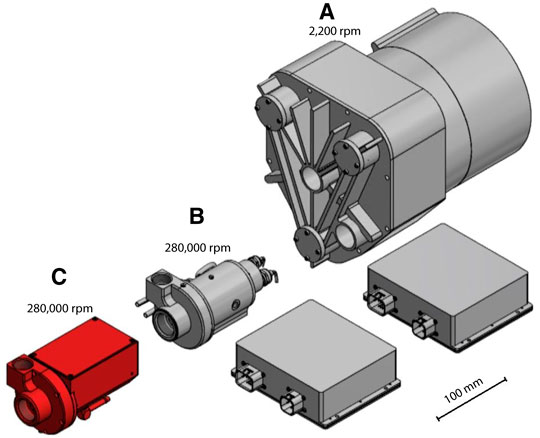
FIGURE 1. Size comparison of (A) state-of-the-art fuel cell scroll compressor (P32H58N2.25 (Air Squared, 2015)) paired with external inverter (CC-120-1000), (B) high-speed air bearing turbo compressor (CT-17-1000 GB (Celeroton, 2017)) paired with external inverter CC-120-1000, and (C) novel high-speed turbo compressor with integrated inverter described in this paper.
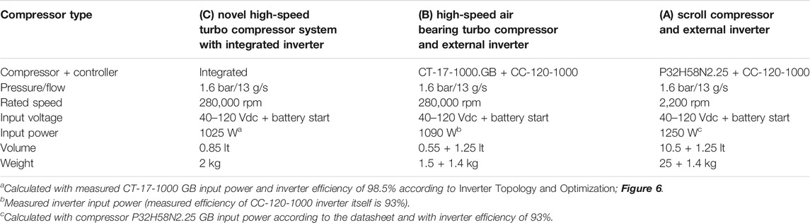
TABLE 1. Performance comparison of (A) state-of-the-art fuel cell scroll compressor (P32H58N2.25 (Air Squared, 2015)) paired with external inverter (CC-120-1000), (B) high-speed air bearing turbo compressor (CT-17-1000.GB (Celeroton, 2017)) paired with external inverter (CC-120-1000), and (C) novel high-speed turbo compressor system with integrated inverter described in this paper. The values given below are for a typical full-load operating point of a 10 kW fuel cell system.
Fuel Cells Systems
Beside the actual fuel cell stack made out of bipolar plates, a fuel cell system requires additional components or auxiliary systems for the actual operation, the so-called Balance of Plant (BoP). Such a fuel cell system and BoP are depicted in Figure 2. The compressor is one of the most important parts to which a large volume fraction, weight, power consumption (around 90%), and cost (around 40%) of the BoP are allocated (James et al., 2017). Furthermore, there is a trade-off between fuel cell stack size and compressor size, as with higher air pressures (requiring higher power and larger compressors), the number of bipolar plates and therefore the stack size and cost can be reduced to achieve the same stack power. Typical pressure levels are between 1.5 bar(a) and 3 bar(a); the required mass flow and therefore the compressor power depend on the stack power. Typically, the compressor uses around 10–20% of the fuel cell output power, i.e., 1–2 kW for a 10 kW fuel cell system.
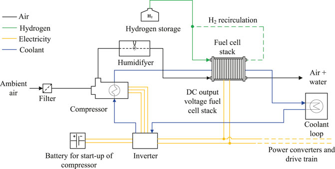
FIGURE 2. Overview of the Balance of Plant (BoP) for an exemplary fuel cell system.
The dc output voltage of the fuel cell stack strongly depends on the power drawn from the stack. For a typical 10 kW fuel cell stack, for example, at no-load condition, a maximum voltage of 120 Vdc is present, while at full load, the fuel cell voltage drops down to 40 Vdc. The inverter driving the motor of the compressor can be supplied either from a battery or from a separate DC/DC converter, which is connected to the fuel cell output and provides a constant dc link voltage to the inverter. However, in order to reduce complexity and increase the efficiency of the BoP, ideally, the inverter is directly connected to the fuel cell output. Therefore, the inverter must cope with a wide input voltage range if directly connected to the fuel cell stack (Zwyssig et al., 2009). Furthermore, during startup, before the fuel cell can produce any electrical power, the compressor must already supply a small amount of air to the fuel cell. Therefore, the inverter must be able to start from a low battery voltage with limited power until the fuel cell generates enough power. Then, the fuel cell enters the self-sustaining operation mode and the compressor inverter can switch to draw its power directly from the fuel cell output voltage. Alternatively, other fuel cell system architectures connect the compressor inverter to the high-voltage battery, which omits the requirement for a separate low voltage battery start but comprises a rather large battery with a compressor inverter input voltage range of, e.g., 200–420 Vdc or 400–750 Vdc.
Further challenges in covering fuel cell system requirements with turbo compressors are described in (Fröhlich, 2019).
Inverter Topology and Optimization
State-of-The-Art Inverter Topology
For drive applications supplied by a dc voltage, such as for the compressor inverter in a fuel cell system, typically a three-phase single-bridge voltage source inverter (SB-VSI) drives a three-phase AC motor having a floating star point. In the case of supplying the inverter with the fuel cell output voltage or a variable high-voltage battery voltage, a dedicated boost-type DC/DC stage may precede the inverter DC/AC stage in order to adapt the fuel cell or battery voltage Ui to a higher dc link voltage Udc. The DC/DC stage guarantees that the nominal motor voltage can be generated, even if the input voltage Ui is inadequately low in the maximum power operating point. Thereby, the two-stage inverter solution of Figure 3 results. The SB-VSI plus DC/DC stage solution exhibits low efficiency/power density due to the two-stage energy conversion and the additional losses/volume originating from the DC/DC stage. In order to generate the nominal motor voltage amplitude of Ûo = Ûo,max, a high dc link voltage of Udc = 2Ûo is required in the case of sinusoidal pulse width modulation (or a dc link voltage of Udc =
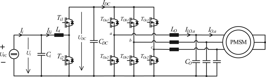
FIGURE 3. State-of-the-art single-bridge voltage source inverter (SB-VSI) solution for motor drives with a wide input-output voltage range. The SB-VSI is a two-stage converter; i.e., a dedicated DC/DC stage steps the battery voltage Ui up to a higher dc link voltage Udc, while a DC/AC stage generates the three-phase motor voltage system. A differential-mode/common-mode (DM/CM) filter is placed before the motor in order to protect the latter from high du/dt.
Double-Bridge Voltage Source Inverter
In order to address the shortcomings of the SB-VSI plus DC/DC stage, the double-bridge voltage source inverter (DB-VSI) technology is proposed (Shivakumar et al., 2001; Lee and Ha, 2013; Wang et al., 2015; Mengoni et al., 2017). The DB-VSI features two VSIs which are connected to the opposite sides of an open-end winding motor as is visualized in Figure 4. An open-end winding motor allows access to both terminals of each phase winding (i.e., terminals a1 and a2 for phase a), in contrast to a conventional motor with a floating star point which provides access to only one terminal per phase (cf. Figure 3). Historically, the DB-VSI originates from high-voltage/power motor drives used in industrial or traction applications (Stemmler and Guggenbach, 1993; Kawabata et al., 1999; Chen et al., 2010; Hatua and Ranganathan, 2011; Han and Ha, 2013) and has been proposed as an alternative to multilevel inverters (Akagi, 2017). A DB-VSI controls the voltage on both sides of the open-end motor winding (in contrast to SB-VSI). Accordingly, the nominal motor phase voltage amplitude of Ûo = Ûo,max can be generated by means of a dc supply voltage of only Ui = Ûo. Thanks to the excellent utilization of the dc supply voltage, it is possible to directly connect the DB-VSI inverter to the fuel cell, without using a dedicated boost-type DC/DC stage; thus, the power P is processed only once and is delivered more efficiently to the motor. Furthermore, the semiconductor devices of the DB-VSI process/switch the low fuel cell nominal voltage of Ui = 40 V. In contrast, the semiconductor devices of the SB-VSI must switch the high dc link voltage Udc = 2Ûo = 80 V in order to generate the same motor phase voltage amplitude Ûo. Since the switching losses of a unipolar semiconductor device scale with the square
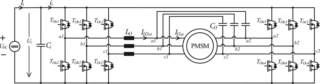
FIGURE 4. DB-VSI inverter solution driving an open-end winding motor. An unfolder modulation is employed; i.e., only one VSI is operated with the switching frequency fs, while the second VSI is operated with the fundamental motor frequency fo. An output filter is placed between the high-frequency-operated VSI and the motor, in order to protect the latter from high du/dt.
In order to integrate the inverter into the compressor housing, the volume of the DB-VSI inverter should be reduced by factor of 2, compared to the state-of-the-art SB-VSI solution. Moreover, the inverter should be able to withstand the high-temperature environment of the motor, which requires a low loss inverter design to limit the temperature gradient between semiconductors and motor/heat sink. The DB-VSI should feature low losses, i.e., achieve a high efficiency η, in order to safely share the same heatsink with the motor. Finally, the overall cost of the inverter/compressor should decrease. That is, the cost saving thanks to the integration (e.g., savings in casing, cables, and connectors) should outweigh any potential cost increase originating from the DB-VSI inverter electronics.
Output Filter
Furthermore, sinusoidal motor voltages are necessary in the case of high-speed motors in order to limit the generated rotor losses (Tuysuz et al., 2013; Schwager et al., 2014; Li et al., 2016). The thermal management of the rotor is a major concern in high-speed motors, since the high rotational speed and the small rotor volume impede the rotor cooling. In order to achieve sinusoidal motor voltages/currents, the DB-VSI of Figure 4 incorporates an output filter. As a further advantage, the depicted output filters mitigate the high du/dt > 30 kV/μs, caused by the latest generation of GaN semiconductor devices (Jones et al., 2015; Bortis et al., 2016a). If not mitigated, high common-mode (CM) du/dt would lead to premature bearing failure due to parasitic CM currents (Baiju et al., 2004; Schroth et al., 2014; Kalaiselvi and Srinivas, 2015), while differential-mode (DM) du/dt would stress the insulation of the motor windings (Kaufhold et al., 2000).
Modulation
The DB-VSI of Figure 4 employs the unfolder modulation (Huber et al., 2008; Marxgut et al., 2014; Antivachis et al., 2020b), as shown in Figure 5. There, only one out of the two VSIs is continuously operated with the switching frequency fs, while the second VSI is operated with the fundamental motor frequency fo. Each phase leg is operated independently of the other two phases; therefore, the analysis of the DB-VSI focuses only on phase-leg a. The discontinuous duty cycles
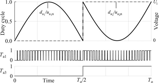
FIGURE 5. Unfolder modulation: only the half-bridge
The terminal motor voltages
The two motor terminal voltages are nonsinusoidal and discontinuous but result in a sinusoidal motor phase voltage
Thanks to the unfolder modulation, the switching losses of the DB-VSI are very low, since the VSI operated with the low fundamental motor frequency fo exhibits negligible switching losses. Furthermore, only the VSI
Multiobjective Optimization
A DB-VSI inverter is designed for the fuel cell specification according to Table 2. There, the selection of the proper switching frequency fs states a crucial design trade-off, since on the one hand, a high switching frequency allows reducing the volume of the passive components but at the same time increases the semiconductor switching losses and accordingly requires a larger semiconductor heat sink volume. In order to select an appropriate switching frequency, a multiobjective optimization routine, with the two objectives of efficiency η and power density ρ, is employed (Kolar et al., 2012; Bortis et al., 2016b). The optimization routine uses a database with a wide range of power electronic components. It includes the 200 V rated EPC2034 GaN semiconductor devices (Guacci et al., 2019), heatsinks of the semiconductor devices (Gammeter et al., 2015), inductive components Lo (Nave, 1991; Burkart et al., 2014; Papamanolis et al., 2018), and ceramic capacitors Co and Ci.
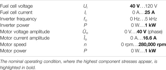
TABLE 2. Variable-speed motor drive specifications.
According to the multi-objective optimization routine, the performance of various inverter designs is assessed concerning power density (ρ) and efficiency (η). For each candidate inverter design, that is, a design featuring a fixed switching frequency fs and a specific set of physical components (e.g., a selected inductor core and winding geometry and a selected semiconductor configuration), the volume and losses of each inverter component are accurately calculated, based on multiphysics models. Subsequently, the volume and losses of all the individual components are added, in order to calculate the candidate inverter design performance {ρ, η}. Whether the rating of the inverter components is exceeded is carefully examined. If the rating of any component is exceeded, e.g., magnetic saturation of inductor core, thermal limit of inductor winding, and current rating of semiconductor devices, then the candidate inverter design is discarded. This process is repeated for a wide range of inverter designs and switching frequencies, while the multiobjective optimization results are shown in Figure 6. There, each candidate inverter design is represented with a point on the {ρ, η} plane.
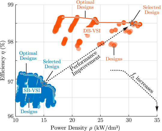
FIGURE 6. Multiobjective optimization results for the DB-VSI and the SB-VSI technology with respect to inverter efficiency η and power density ρ, for a design space with different switching frequencies fs, semiconductor devices, inductance values Lo, and capacitance values Co and Ci. The selected DB-VSI design is highlighted with a star and the respective component values are given in Table 3.
Based on the optimization results, a benchmark design {ρ = 31 kW/dm3, η = 98.5%} is selected, featuring a switching frequency of fs = 300 kHz. Note that the calculated power density accounts for only the boxed volume of inverter components. In reality, a hardware prototype achieves 40–50% lower power density, due to the unaccounted volume of the air between the components and of the control electronics. The detailed design process of a DB-VSI can be found in (Antivachis et al., 2020a), while the parameters of the selected benchmark designs are given in Table 3.
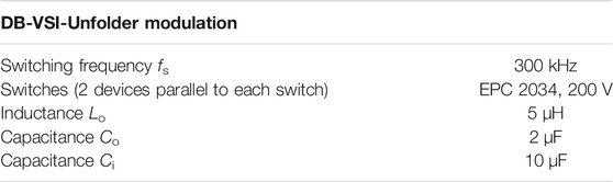
TABLE 3. DB-VSI hardware prototype parameters corresponding to the schematic diagram notation of Figure 4.
For the sake of completeness, a benchmark system consisting of a conventional SB-VSI (cf. Figure 3) is designed for the specifications of Table 2. The detailed design process of an SB-VSI is also found in (Antivachis et al., 2020). The results of the performed multiobjective optimization routine are depicted in Figure 6. As can be noted, the selected SB-VSI benchmark design {ρ = 15 kW/dm3, η = 96.9%} features the same switching frequency of fs = 300 kHz, for both the DC/DC stage and the DC/AC stage.
A comparison of the multiobjective optimization results for the SB-VSI and the DB-VSI technology in Figure 6 reveals that the DB-VSI significantly outperforms the conventional SB-VSI. In particular, the DB-VSI benchmark design generates roughly half the losses and achieves twice the power density compared to the respective SB-VSI design, for the same switching frequency and semiconductor technology. There are two main reasons behind this large performance gap:
The SB-VSI features two energy conversion stages (DC/DC stage and DC/AC stage) and thus employs four inductors in total. In contrast, the DB-VSI is a single-stage inverter and thus uses only three inductors, allowing for a significantly higher power density.
The semiconductor devices of both the DC/DC stage and the DC/AC stage of the SB-VSI have to process/switch the high DC link voltage UDC = 80 V. In contrast, the DB-VSI is directly connected to the fuel cell; thus, all the semiconductor devices process/switch the low fuel cell voltage Ui = 40 V. Accordingly, the DB-VSI benefits from lower switching losses and thus achieves higher efficiency.
Compressor Design and Integration
Aerodynamic, Air Bearing, and Motor Design
The aerodynamic, air bearing, and motor design are taken from an existing high-speed air bearing turbo compressor CT-17-1000 GB (Celeroton 2017). Therefore, the novel high-speed turbo compressor with integrated inverter achieves the same rated pressure ratio and flow rate as the existing compressor CT-17-1000 GB driven by the external inverter CC-120-1000. The aerodynamic design of this compressor is described in (Casey et al., 2013) and (Zhao et al., 2012). A herringbone fluid film journal and thrust bearing is employed, designed according to the narrow groove theory described in (Looser 2013) and (Schiffmann 2008). The motor is a permanent magnet synchronous motor (PMSM) employing a slotless type winding as described in (Looser et al., 2012).
Electrical Integration
The high DB-VSI power density enables seamless integration of the inverter in the compressor housing [17]–[19]. In contrast to most electrical drive systems, where three cables are present between motor and inverter, and a star point is formed within the motor stator; in the presented DB-VSI, all six motor phase terminals are connected to the inverter. In a standard compressor configuration having separated motor/compressor and inverter units, the high number of motor terminals would clearly be a drawback; however, with the inverter integration into the motor/compressor, this is no more an issue. The open-end winding motor is directly attached to the inverter, eliminating the need for cumbersome and costly shielded motor cables. From an electrical perspective, there are the following advantages of the integrated inverter:
Reduced EMI noise emission caused by high-frequency currents in the motor phase connections since the compressor housing acts as a shield against radiation or like a low-inductive common-mode path for any CM currents.
Single connector interface to the fuel cell system, whereas in the standard configuration, at least three connectors are required (one on motor side and two on inverter side).
The inverter is also equipped with a low voltage input (ULV) in order to drive the compressor from a low voltage battery supply during the fuel cell startup (LV start or battery start, cf. Fuel Cells Systems). Furthermore, even though the control electronics are integrated into the motor housing and thus sensor cables could be made short, a rotor position sensor is omitted to reduce hardware complexity and in turn increase system reliability. Instead, an observer to estimate the rotor angular position ε and angular speed ω is implemented in software, which is also denominated as sensorless control. On the motor control level, a cascaded control structure with an inner current/torque control loop and an outer speed control loop is employed, allowing for variable-speed mission profiles and system protection where different current and speed limits can be set. A block diagram of the turbo compressor drive system is depicted in Figure 7.
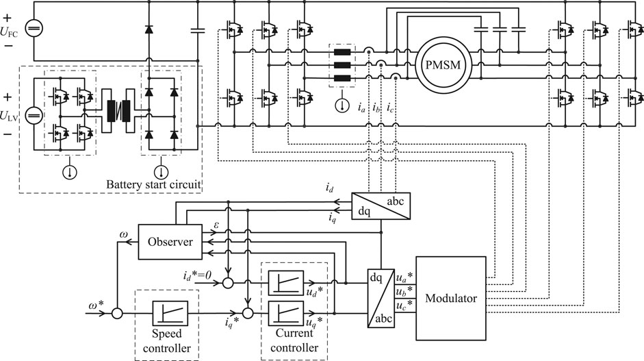
FIGURE 7. Electrical circuit diagram of the novel high-speed turbo compressor system with integrated inverter, including sensors and control.
Mechanical and Thermal Integration
Figure 8 shows a CAD drawing of the novel high-speed turbo compressor system with integrated inverter. The goal of the mechanical integration of the inverter in the compressor system is to design a system with maximum power density and a minimum number of interfaces. The maximum diameter of the compressor housing is defined by the aerodynamic design. The motor itself has a smaller diameter, and therefore, the inverter is arranged in several parts around the motor in order to make the best possible use of the volume given by the cylindrical motor shape as shown in Figure 8.
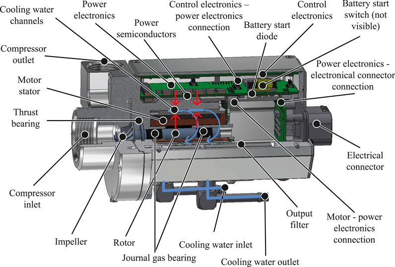
FIGURE 8. CAD drawing of a novel high-speed turbo compressor system with an integrated inverter. Temperature sensors for the experimental verification are installed in the motor stator, at the output filter, battery start switch, battery start diode, and inverter power semiconductors in order to verify the cooling concept. The red arrows represent the heat flow from the inverter and the motor to the coolant. The blue arrows indicate the coolant flow.
The volume of the cooling system is minimized in such a way that the cooling channels of the water cooling are passing between the motor and power electronics and therefore can dissipate both the compressor and inverter losses (cf. Figure 8). There, the cooling system is designed to have a low-pressure drop of a maximum of 300 mbar in order to achieve a high flow rate of the coolant of around 3 L/min, which are typical values for fuel cell cooling loops.
The power semiconductors, inductors, and capacitors are designed for a hotspot temperature of 120 °C. However, due to measurement uncertainties and due to the deviation between sensor position and thermal hotspots, 90 °C is set as a thermal limit for the measured temperatures in the passive and active components of the inverter in the experimental verification in Experimental Verification as well as in the inverter control software for the monitoring of the integrated temperature sensors in motor winding and power electronics PCB. The hotspot temperature of the motor stator winding is around 130–150 °C, but the thermal gradient within the stator results in similar temperatures at the stator interfaces; hence, its temperature limit is also set to 90 °C.
Comparing CT-17-1000 GB plus external inverter CC-120-1000 and the novel turbo compressor with integrated inverter, a total volume and weight reduction of around 50% are achieved. A performance comparison is given in Table 1 and the size comparison is shown in Figure 1. As can be noted, the novel compressor system with integrated inverter reduces the number of interfaces to only five, two adapters for the cooling water supply, two adapters for the main compressor inlet and outlet flow, and one single electrical connector, and omits any external cabling between inverter and compressor.
Experimental Verification
Test Setup
Figure 9 shows the novel compressor with an integrated inverter attached to the test bench environment. Due to availability, an existing impeller and volute of a CT-17-700 GB compressor is used, which achieves the same pressure ratio as the CT-17-1000 GB but has a reduced mass flow and power rating of 70% of the CT-17-1000 GB.
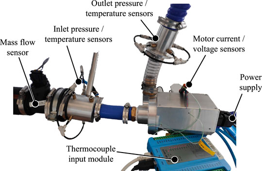
FIGURE 9. Compressor with an integrated inverter installed in test bench environment.
In order to verify the thermal management, temperature sensors are attached to different inverter components, i.e., to the battery start diode, battery start switch, output filter, power semiconductor, and motor stator. The physical locations of the temperature sensors are shown in Figure 8.
The test bench is equipped with additional sensors to measure compressor inlet pressure and temperature, outlet pressure, and mass flow to verify the aerodynamic performance of the compressor. In addition, the electrical input power to the inverter is measured allowing us to characterize the complete compressor power and efficiency performance.
Finally, motor current and voltage measurements are implemented in order to verify the current modulation schemes of the inverter control.
Measurements
The measurements of phase voltages and currents, depicted in Figure 10, verify that nearly sinusoidal motor currents can be achieved and therefore low rotor losses are induced. Table 4 shows the results of the thermal measurements at maximum power (OP1) and additional measurements at maximum pressure ratio (OP2) for the CT-17-700 GB aerodynamic design with a coolant temperature of around 27 °C. The operating points are marked in the compressor and the power map in Figure 11. All measured temperatures are at least 30 degrees below the thermal limit of 90 °C; thus, the maximum coolant temperature can be increased to around 55 °C as a linear scaling between motor and inverter temperatures and coolant temperature is expected.
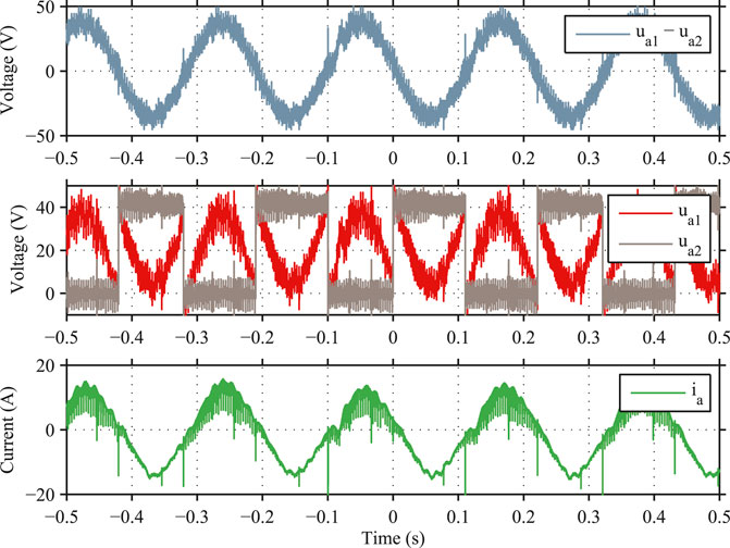
FIGURE 10. Output voltage and current measurement of the novel high-speed turbo compressor system with integrated inverter.
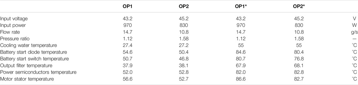
TABLE 4. Temperature measurements of critical parts of compressor with integrated inverter (for maximum power (OP1) and maximum pressure ratio (OP2) according to Figure 11) and linear extrapolation to operating points with higher coolant temperature of 55 °C (OP1* and OP2*) complying with the temperature limit of 90 °C for the critical parts.
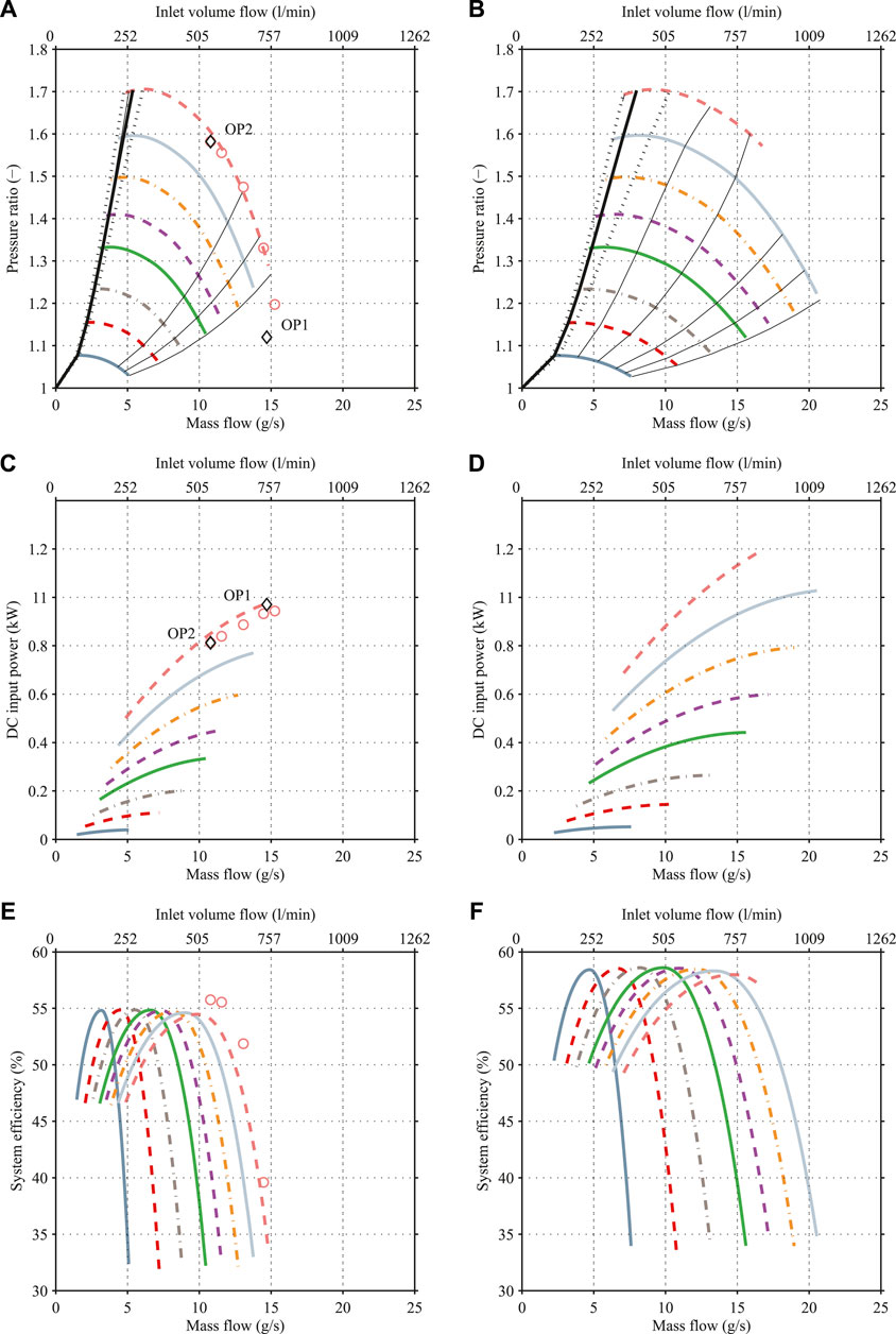
FIGURE 11. Calculated and measured performance maps of the compressor with integrated inverter and aerodynamic design of the CT-17-700 GB compressor (A, C, E) and with the aerodynamic design of the CT-17–1000 GB compressor (B, D, F). The pressure ratio maps are shown in (A, B), the power maps in (C, D), and the efficiency maps in (E, F). Measurement results are visualized by circles. The black diamonds show the operating conditions of the temperature measurements, summarized in Table 4.
Figure 12 shows the measured pressure drop with respect to the coolant volume flow. The cooling water pressure is measured at the inlet and outlet of the cooling channel. The resulting pressure drop at 3 L/min is below the design limit of 300 mbar.
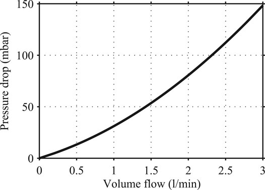
FIGURE 12. Cooling channel pressure drop of the compressor with an integrated inverter.
Figures 12A,C,E show the measurement and calculated performance maps of the novel high-speed turbo compressor system with integrated inverter and the aerodynamic design of the CT-17-700 GB. Figure 11A shows the pressure ratio as a function of the mass flow. The pressure ratio is calculated by means of the inlet and outlet pressure, whose locations are shown in Figure 11. Figure 11C shows the system power depending on the mass flow. The system input power is measured by a power analyzer at the dc input of the inverter. Figure 11E shows the system efficiency with respect to the mass flow. The system efficiency is calculated by means of the measured system input power and the aerodynamic power, which is determined by means of inlet/outlet pressure and gas properties.
The comparison between measured and calculated pressure ratio vs. mass flow shows good agreement. This result was expected, since the aerodynamic design of the compressor is adopted from the commercial CT-17-700 GB compressor. The input to output pressure difference is around 3% lower and the efficiency is around 2% higher (cf. Figure 11E) than calculated. Therefore, the input power is around 4% lower than calculated (cf. Figure 11C). The potential reason is the variations in efficiency and therefore input power within compressors of the same product series, which are in the same magnitude of 2–3% due to bearing and tip clearance variations. Therefore, for statistical reasons, multiple products would have to be experimentally investigated to assess the average efficiency improvement. A similar result with minor deviations between design and measurement is expected for the novel high-speed turbo compressor system with integrated inverter and the aerodynamic design of the CT-17-1000 GB compressor, resulting in the performance maps depicted in Figures 11B,D,F.
Conclusion
This paper presents a novel high-speed turbo compressor with integrated inverter (cf. Figure 1). This integrated compressor/inverter concept is suitable for fuel cell air supply and other air handling and boosting applications, which put a high requirement on small size, high efficiency, and low complexity. The integration of the inverter complements the already compact compressor (based on high-speed turbomachinery) and is enabled by using the double-bridge voltage source inverter (DB-VSI) technology, shown in Figure 4. The DB-VSI, in conjunction with the latest generation of GaN saemiconductor devices and multiobjective optimization techniques, allows halving the volume of the inverter; hence, the inverter fits into the small physical dimensions of the compressor housing.
Simultaneously, the DB-VSI achieves a 5.5% increase in efficiency (from 93 to 98.5%) compared to an existing industrial inverter and a 2.6% increase in efficiency (from 96.9 to 98.5%) compared to the standard single-bridge voltage source inverter with a front-end boost stage (SB-VSI) of Figure 3. Furthermore, the improved phase current quality of the DB-VSI, compared to the industrial inverter, reduces the motor rotor losses and further increases the compressor system efficiency.
The integration of the inverter in the compressor housing allows for a reduction of the compressor system (turbo compressor and inverter) size by a factor of two. In addition, a turbo compressor with an integrated inverter reduces complexity and cost for operators by savings in casing, cables, coolant piping, and connectors. The experimental verification with a 280,000 rpm, 1 kW turbo compressor, shows that the temperature limits for the power electronics parts are kept below the limit of 90 °C up to a coolant temperature of 55 °C, while the coolant pressure drop is kept well below its limit of 300 mbar at 3 L/min. Finally, the overall efficiency of the compressor system is increased by 5.5% (cf. Table 1) compared to a state-of-the-art turbo compressor without an integrated inverter.
Data Availability Statement
The raw data supporting the conclusion of this article will be made available by the authors, without undue reservation.
Author Contributions
All authors listed have made a substantial, direct, and intellectual contribution to the work and approved it for publication. All authors contributed to the article and approved the submitted version.
Funding
This research has been supported by the Swiss Innovation Agency (Innosuisse).
Conflict of Interest
The authors declare that the research was conducted in the absence of any commercial or financial relationships that could be construed as a potential conflict of interest.
References
Air Squared (2015). P32H58N2.25 scroll compressor. Available at: https://airsquared.com/wp-content/uploads/2015/05/p32h058a-bldc.pdf. (Accessed 02 09 2020).
Akagi, H. (2017). Multilevel converters: fundamental circuits and systems. Proc. IEEE. 105 (11), 2048–2065. doi:10.1109/JPROC.2017.2682105
Antivachis, M., Anderson, J. A., Bortis, D., and Kolar, J. W. (2020a). Analysis of a synergetically controlled two-stage three-phase dc/ac buck-boost converter. CPSS TPEA. 5 (1), 34–53. doi:10.24295/CPSSTPEA.2020.00004
Antivachis, M. M. (2020). Analysis and multi-objective evaluation of new three-phase pwm inverter system. Dissertation. Zurich, Switzerland; ETH Zurich.
Antivachis, M., Wu, D., Bortis, D., and Kolar, J. W. (2020b). Analysis of double-bridge inverters for drive systems with open-end winding motors. IEEE J. Emerging Sel. Top. Power Electron. 99, 1. doi:10.1109/JESTPE.2020.3017085
Baiju, M. R., Mohapatra, K. K., Kanchan, R. S., and Gopakumar, K. (2004). A dual two-level inverter scheme with common mode voltage elimination for an induction motor drive. IEEE Trans. Power Electron. 19 (3), 794–805. doi:10.1109/TPEL.2004.826514
Blunier, B., and Miraous, A. (2010). Proton exchange membrane fuel cell air management in automotive applications. J. Fuel Cell Sci. Technol. 7, 041007. doi:10.1115/1.4000627
Bortis, D., Knecht, O., Neumayr, D., and Kolar, J. W. (2016a). “Comprehensive evaluation of gan git in low- and high-frequency bridge leg applications.” in Proceedings of IEEE 8th International Power Electronics and Motion Control Conference (IPEMC-ECCE Asia), Hefei, China, May 2016.
Bortis, D., Neumayr, D., and Kolar, J. W. (2016b). “ηρ-pareto optimization and comparative evaluation of inverter concepts considered for the google little box challenge.” in Proceedings of IEEE 17th Workshop on Control and Modeling for Power Electronics (COMPEL), Trondheim, Norway, June 2016.
Burkart, R. M., Uemura, H., and Kolar, J. W. (2014). “Optimal inductor design for 3-phase voltage-source pwm converters considering different magnetic materials and a wide switching frequency range.” in Proceedings of International Power Electronics Conference (IPEC - ECCE Asia), Hiroshima, Japan, May 2014, 891–898.
Casey, M. V., Krähenbuhl, D., and Zwyssig, C. (2013). “The design of ultra-high-speed miniature centrifugal compressors.” in European conference on Turbomachinery Fluid Dynamics and Thermodynamics ETC, Lappeenranta, Finland, March 2013, 1–13.
Celeroton (2016). The technical application is defined, the pressure rise and the mass flow are determined, but which compressor type is the right one for this application? Available at: https://www.celeroton.com/en/technology/tech-blog/detail/is-an-ultra-high-speed-turbo-compressor-the-right-compressor-for-your-application.html. [Accessed 01 09 2020].
Celeroton (2017). CT-17-1000.GB. Available at: https://www.celeroton.com/fileadmin/user_upload/produkte/kompressor/datasheets/Datenblatt-CT-17-1000.GB.pdf. (Accessed 02 09 2020).
Chen, K., Delarue, P., Bouscayrol, A., Vidal, P.-E., and Pietrzak-David, M. (2010). Minimum copper loss and power distribution control strategies of double-inverter-fed wound-rotor induction machines using energetic macroscopic representation. IEEE Trans. Energy Convers. 25 (3), 642–651. doi:10.1109/TEC.2009.2025414
Fröhlich, P. (2019). “Development of an oil free turbo compressor for mobile fuel cell applications–challenges and results.” in Konferenzband der ersten FC³ Fuel Cell Conference, Chemnitz, Germany, November 2019, 123–138.
Gammeter, C., Krismer, F., and Kolar, J. W. (2015). Weight optimization of a cooling system composed of fan and extruded-fin heat sink. IEEE Trans. Ind. Appl. 51 (1), 509–520. doi:10.1109/TIA.2014.2336977
Guacci, M., Azurza, J., Pally, K., Kolar, J. W., Bortis, M., et al. (2019). Experimental characterization of silicon and gallium nitride 200V power semiconductors for modular/multilevel converters using advanced measurement techniques. IEEE Trans. Emerg. Sel. Topics Power Electron. 99, 1. doi:10.1109/JESTPE.2019.2944268
Han, Y., and Ha, J. (2013). “Single external source control of doubly-fed induction machine using dual inverter.” in Proceedings of IEEE Energy Conversion Congress and Exposition, Denver, CO, September 2013, 2079–2085.
Hatua, K., and Ranganathan, V. T. (2011). A novel vsi- and csi-fed dual stator induction motor drive topology for medium-voltage drive applications. IEEE Trans. Ind. Electron. 58 (8), 3373–3382. doi:10.1109/TIE.2010.2081958
Hava, A. M., Kerkman, R. J., and Lipo, T. A. (1999). Simple analytical and graphical methods for carrier-based pwm-vsi drives. IEEE Trans. Power Electron. 14 (1), 49–61. doi:10.1109/63.737592
Huber, L., Jang, Y., and Jovanovic, M. M. (2008). Performance evaluation of bridgeless pfc boost rectifiers. IEEE Trans. Power Electron. 23 (3), 1381–1390. doi:10.1109/TPEL.2008.921107
James, B., Huya-Kouadio, J., Houchins, C., and Desantis, D. (2017). Mass production cost estimation of direct H2 PEM fuel cell systems for transportation applications: 2017 update, 55683. doi:10.13140/RG.2.2.36532
Jones, E. A., Wang, F., Costinett, D., Zhang, Z., Guo, B., Liu, B., et al. (2015). “Characterization of an enhancement-mode 650-v gan hfet.” in Proceedings of IEEE Energy Conversion Congress and Exposition (ECCE USA), Montreal, Canada, September 2015, 400–407.
Kalaiselvi, J., and Srinivas, S. (2015). Bearing currents and shaft voltage reduction in dual-inverter-fed open-end winding induction motor with reduced cmv pwm methods. IEEE Trans. Ind. Electron. 62 (1), 144–152. doi:10.1109/TIE.2014.2336614
Kaufhold, M., Aninger, H., Berth, M., Speck, J., and Eberhardt, M. (2000). Electrical stress and failure mechanism of the winding insulation in pwm-inverter-fed low-voltage induction motors. IEEE Trans. Ind. Electron. 47 (2), 396–402. doi:10.1109/41.836355
Kawabata, Y., Ejiogu, E., and Kawabata, T. (1999). Vector-controlled doubleinverter-fed wound-rotor induction motor suitable for high-power drives. IEEE Trans. Ind. Appl. 35 (5), 1058–1066. doi:10.1109/ELNANO.2018.8477531
Kim, K. H., and Youn, M. J. (2002). Performance comparison of pwm inverter and variable dc link inverter schemes for high-speed sensorless control of bldc motor. Electron. Lett. 38 (21), 1294–1295. doi:10.1049/el:20020848
Kolar, J., Krismer, F., Lobsiger, Y., Muhlethaler, J., Nussbaumer, T., and Minibock, J. (2012). “Extreme efficiency power electronics.” in Proceedings of 7th International Conference on Integrated Power Electronics Systems (CIPS), Nuremberg, Germany, March 2012, 1–22.
Lee, Y., and Ha, J. (2013). “Power enhancement of dual inverter for open-end permanent magnet synchronous motor.” in Proceedings of 28th Annual IEEE Applied Power Electronics Conference and Exposition (APEC), Long Beach, CA, March 2013, 1545–1551.
Li, S., Li, Y., Choi, W., and Sarlioglu, B. (2016). High-speed electric machines: challenges and design considerations. IEEE Transactions on Transportation Electrification. 2 (1), 2–13. doi:10.1109/TTE.2016.2523879
Looser, A., Baumgartner, T., Kolar, J. W., and Zwyssig, C. (2012). Analysis and measurement of three-dimensional torque and forces for slotless permanent-magnet motors. IEEE Trans. Ind. Appl. 48 (4), 1258–1266. doi:10.1109/TIA.2012.2199070
Looser, A. E. (2013). Gas bearing with active magnetic damping for ultra-high-speed electrical drive systems. Dissertation. Zurich, Switzerland: ETH Zurich.
Marxgut, C., Krismer, F., Bortis, D., and Kolar, J. W. (2014). Ultraat interleaved triangular current mode (tcm) single-phase pfc rectifier. IEEE Trans. Power Electron. 29 (2), 873–882. doi:10.1109/TPEL.2013.2258941
Mengoni, M., Amerise, A., Zarri, L., Tani, A., Serra, G., and Casadei, D. (2017). Control scheme for open-ended induction motor drives with a oating capacitor bridge over a wide speed range. IEEE Trans. Ind. Appl. 53 (5), 4504–4514. doi:10.1109/TIA.2017.2704910
Nave, M. J. (1991). “On modeling the common mode inductor.” in Proceedings of IEEE International Symposium on Electromagnetic Compatibility, Cherry Hill, NJ, July 12–August 16, 1991, 452–457.
Papamanolis, P., Krismer, F., and Kolar, J. W. (2018). “Minimum loss operation of high-frequency inductors.” in Proceedings of IEEE Applied Power Electronics Conference (APEC), San Antonio, TX, March 2018, 1756–1763.
Schiffmann, J. (2008). Integrated design, optimization and experimental investigation of a direct driven turbocompressor for domestic heat pumps. Dissertation. Lausanne, Switzerland: EPFL.
Schroth, S., Bortis, D., and Kolar, J. W. (2014). “Impact of stator grounding in low power single-phase ec-motors.” in Proceedings of IEEE Applied Power Electronics Conference and Exposition (APEC), Fort Worth, TX, March 2014, 783–790.
Schwager, L., Tuysuz, A., Zwyssig, C., and Kolar, J. W. (2014). Modeling and comparison of machine and converter losses for pwm and pam in highspeed drives. IEEE Trans. Ind. Appl. 50 (2), 995–1006. doi:10.1109/TIA.2013.2272711
Shivakumar, E. G., Gopakumar, K., Sinha, S. K., Pittet, A., Ranganathan, V. T., et al. (2001). “Space vector pwm control of dual inverter fed open-end winding induction motor drive.” in Proceedings of 16th Annual IEEE Applied Power Electronics Conference and Exposition (APEC) 1, 399–405.
Stemmler, H., and Guggenbach, P. (1993). “Configurations of high-power voltage source inverter drives.” Proceedings of 5th European Conference on Power Electronics and Applications, Brighton, United Kingdom, September 1993, 5, 7–14.
Taniguchi, K., and Okumura, A. (1993). “A pam inverter system for vector control of induction motor.” in Conference Record of the Power Conversion conference-Yokohama, Yokohama, Japan, April 1993, IEEE, 478–483.
Tuysuz, A., Schaubhut, A., Zwyssig, C., and Kolar, J. W. (2013). Model-based loss minimization in high-speed motors. Proceedings of International Electric Machines Drives Conference (IEMDC), 332–339. doi:10.1109/IEMDC.2013.6556272
Wang, B., Localzo, G., El Murr, G., Wang, J., Griffo, A., Gerada, C., et al. (2015). “Overall assessments of dual inverter open winding drives.” in Proceedings of IEEE International Electric Machines Drives Conference (IEMDC), Coeur d’Alene, ID, May 2015, 1029–1035.
Zhao, D., Daniel, K., Blunier, B., Zwyssig, C., Dou, M., and Miraoui, A. (2012). “Design and control of an ultra high speed turbo compressor for the air management of fuel cell systems.” in IEEE Transportation Electrification Conference and Expo, Dearborn, MI, June 2012, 1–6.
Zwyssig, C., Duerr, M., Hassler, D., and Kolar, J. W. (2007). An ultra-high-speed, 500000 rpm, 1 kW electrical drive system.” Power Conversion Conference-Nagoya. Nagoya, Japan, January 2007, IEEE, 1577–1583.
Keywords: compact, fuel cell, centrifugal compressor, high-speed, electrical motor, turbo compressor, integrated inverter, air bearing
Citation: Antivachis M, Dietz F, Zwyssig C, Bortis D and Kolar JW (2021) Novel High-Speed Turbo Compressor With Integrated Inverter for Fuel Cell Air Supply. Front. Mech. Eng 6:612301. doi: 10.3389/fmech.2020.612301
Received: 30 September 2020; Accepted: 30 November 2020;
Published: 26 February 2021.
Edited by:
Sriram S. Popuri, Cummins (United States), United StatesReviewed by:
Vaidehi Hoshing, Cummins (United States), United StatesAshish Vora, Tesla, Inc., United States
Nayan Engineer, Aramco Research Centers, United States
Copyright © 2021 Antivachis, Dietz, Zwyssig, Bortis and Kolar. This is an open-access article distributed under the terms of the Creative Commons Attribution License (CC BY). The use, distribution or reproduction in other forums is permitted, provided the original author(s) and the copyright owner(s) are credited and that the original publication in this journal is cited, in accordance with accepted academic practice. No use, distribution or reproduction is permitted which does not comply with these terms.
*Correspondence: Dominik Bortis, Ym9ydGlzQGxlbS5lZS5ldGh6LmNo