 Marco Nicola Mastrone
 Franco Concli
- Faculty of Science and Technology, Free University of Bolzano, Piazza Università, Bolzano, Italy
Energy efficiency is among the predominant aspects in mechanical design. Geared transmissions are widespread in several industrial applications and efficiency's improvements translate into various benefits, e.g., reduction of pollutants' emissions, better system's reliability due to lower operating temperatures, and higher power density. The possibility to compare different solutions in the preliminary stages of the design phase plays a determinant role to the achievements of these targets. In particular, Computational Fluid Dynamics (CFD) can be adopted to analyze the problem of interest overcoming the limitations of the analytical equations. On the other side, the application of numerical models to gears, in which the topology of the domain changes during operation, represents a challenging task and tailored mesh handling algorithms must be implemented. In the current paper, the power losses of a spiral bevel gear were examined numerically with an opensource tool. The predictions of the numerical models were compared with experimental data. The approach adopted shows a good computational effort making it useful for parametrical studies and, therefore, suggests being an effective tool for the analysis of the gearboxes' efficiency and lubrication.
Introduction
Geared transmissions are one of the most widespread systems to transmit power. To design such mechanical systems against failure mechanism as pitting, scuffing and wear, it is important to be able to accurately calculate their efficiency and operating temperature, since they directly impact the reliability of the system. Empirical models derived from experiments allow engineers to compute the power losses due to gear meshing and sliding accurately (load-dependent power losses). However, for the losses that arise from the interaction with the fluid (no-load losses), the analytical formulations available in literature are not accurate enough since they are limited to the operating conditions of the experiments and do not consider some influencing parameters.
Initial studies on this argument were done by Ohlendorf (1958), Daily and Nece (1960), Mann and Marston (1961), and Soo and Princeton (1958), who examined a rotating gear immersed in lubricant oil and proposed some analytical formulations for the mathematical description of the power losses in the gearbox. Works specifically dealing on the churning effect were presented by Lauster and Boos (1983), Boness (1989), and Seetharaman et al. (2009).
One of the most complete model available in literature to describe the power losses in several operating conditions was given by Mauz (1987). He analyzed the power losses that originate by the interaction between the lubricant and gears, and provided useful results on the lubricant distribution inside the transmission exploiting a transparent housing. This is the first model that is capable of considering mating gears in the equation of the losses and represents still today a milestone in the sector of tribology. However, although it is one of the most complete models available in literature, it has some limits related to the applicability to different systems configurations. For example, the formulations can consider only spur gears (therefore excluding helical, bevel, and hypoid transmissions). Moreover, some limits on the reduction ratio and the tangential velocity of the wheels do not allow to apply the model to mechanical systems that exceed these thresholds, and, therefore, some limitations on the design on new gearboxes are present.
Systematic investigations by Terekhov (1975) highlighted the influence of several parameters (both geometrical of the gears and physical of the lubricant) on squeezing and churning power losses for dip-lubricated gears. Walter (1982) extended the equations proposed by Terekhov. More recent experimental investigations were presented by Changenet and Velex (2007), who proposed an equation whose parameters have to be calibrated according to the Reynolds number and Froude number.
All the analytical formulations available in literature represents an important point in the knowledge of lubrication and efficiency of gearboxes, but their limitations do not allow their extension to more complex systems. Newly, simulation software packages are becoming an essential tool for engineers in mechanical design. Indeed, they offer the possibility to study all configurations (theoretically) without geometrical and physical constraints. Moreover, the step from physical to virtual prototypes consistently lower the costs of the design phase (especially if opensource software are used) and is a key aspect in Industry 4.0. However, the physics needed in the simulation of gearboxes is composed by several aspects (multiphase simulations with moving boundaries) that must be considered simultaneously and that require a significant computational effort. With the availability of High Performing Computers (HPCs) the time effort issue can be overcome, at least partially, by exploiting parallel calculations. Nevertheless, the correct imposition of the motion to the rotating gears requires a deep knowledge of the mesh motion algorithms available, and their pros and cons. The authors have applied different CFD approaches to study the efficiency of gearboxes. In particular, the global remeshing approach (Concli and Gorla, 2013; Concli, 2017; Mastrone et al., 2020) was exploited to study mating gears and planetary configurations, while the multiple reference frame and the sliding mesh approaches (Concli et al., 2015) were applied to helical and spur gears. Available studies on spiral bevel gears can be found in Webb et al. (2010), who investigated the windage losses of a single gear. They exploited the sectorial symmetry of the domain (i.e., only one sector of the gear was modeled) and the Multi Reference Frame (MRF) to account for the boundary's motion. Turner et al. (2013) studied the same case of Webb et al. with the addition of oil droplets falling on the teeth flanks, concluding that it is still not possible to assess the ability of the model to simulate the bulk transport of droplets and that further works in this field are necessary. Hu et al. (2019) studied the power losses of an intermediate gearbox of a helicopter. The influence of several parameters was analyzed numerically showing the ability of the model to capture the physical phenomena involved in dip lubricated conditions, although the calculated power losses are not compared to experimental data. Peng et al. (2018) implemented a numerical model for hypoid gears, showing the capability of the simulations to reproduce the oil flow observed experimentally and to predict the measured power losses accurately. In this work, a numerical model based on the sliding mesh approach was exploited to analyze the power losses of a spiral bevel gear. The uncommon behavior of the losses was the main reason for this study that is aimed on one hand to better understand the physical reason behind this evidence and on the other hand to evaluate the applicability, accuracy, and efficiency of CFD codes applied to the bevel gears.
Description of the Problem
Two different types of losses are generally present in gearboxes: load dependent and no-load losses. The former are related to transmitted load, while the latter depend on the lubricant characteristics (which depend in turn on the temperature) and the geometrical constraints in the gearbox that affect the lubricant distribution. Niemann and Winter (2003) classified the power losses of a generic lubricated system as:
meaning that the total power losses are given by the sum of the load dependent and the no-load losses of each mechanical component of the system (subscript |0 stands for no-load losses; subscript |G stands for gears; subscript |B stands for bearings; subscript |S stands for seals; subscript |X stands for any other component, e.g., clutches.
For the losses that depend on the transmitted load several formulations are provided by the manufacturers. These are usually very accurate since they come from years and years of experimental testing. On the other hand, the no-load losses (due to the interaction with the lubricant) can benefit from further studies in terms of accuracy and applicability. In particular, the application of CFD to the study of these phenomena can provide engineers with useful information on the efficiency and on the lubrication of gearboxes that would be complex to gather experimentally. Moreover, it would be possible to perform parametrical studies collecting significant amount of data by changing the input parameters through a script. The application of CFD to these cases has grown up tremendously in the last year, suggesting that more and more researchers are exploring this line of research and appreciating the huge advantages of numerical tools. The time invested in learning a simulation tool is for sure repaid in terms of possibility of advancements in the understanding of lubrication and tribology.
The no-load power losses of gears PLG0 is given by three distinct contributions:
where the pocketing/squeezing are represented by PLG0,S; the windage losses are represented by PLG0,W; and the splashing/churning losses are represented by PLG0,C. These three contributions refer to completely different physical phenomena: the pocketing effects are related to the fact that during the gears' rotation the mixture is squeezed between the teeth determining pressure gradients axial lubricant fluxes; the windage effect arise from the interaction between the wheels and air (in the multiphase case) or lubricant (in case of a gearbox completely filled with oil); the churning effects come from the resistance of the lubricant to the wheels movement.
Numerical Modeling of the Problem
CFD software are based on the solution of three governing equations: mass, momentum, and energy equation. In this study, the problem was modeled as isothermal. Therefore, the energy equation was not activated. In this way, the solution is limited to the mass and momentum equations which can be written as:
where u represents the fluid velocity, ρ represents the fluid density, μ is the viscosity, g represents the gravity acceleration, and F is the vector of external forces.
These equations are valid only in simulations involving one phase. This condition is not realistic in gearboxes. In fact, phenomena like cavitation and aeration, which imply continuous phase transitions, are not considered in the shown equations. Therefore, it is necessary to introduce a balance equation that take into account the presence of two or more phases. This quantity is represented by the volumetric fraction, which represents the percentage of one fluid in every discretized cell. With this approach, the properties of the equivalent fluid are computed as the average of the properties of each individual fluid. In this way, the density and the viscosity are formulated as:
where the subscripts |1 and |2 stand for the two fluids in consideration (e.g., air and oil). The equation of the volumetric fraction can be expressed as follows:
The solution of this equation can give problems in CFD simulations since it can make the values of alfa exploding. This fact is even more amplified in case of moving boundaries as in gearboxes. In order to improve the solution of the volumetric fraction equation (that must be bounded between 0 and 1), a compressive scheme is usually adopted. A dummy velocity vector (uc) in the proximity of the interface is added so that the local flow steepens the gradient of the volume fraction function, thus improving the interface resolution. In this work, the MULES (Multidimensional Universal Limiter with Explicit Solution) approach was exploited. The alfa equation becomes:
In order to consider the possible phase change, an additional source term must be added to the equation:
To calculate the source term, a phase change model must be introduced. The most used in CFD are those by Merkle et al. (1998), Kunz et al. (2000), and Saurer (2000). With the above-mentioned equation, it is possible to model all operating conditions including cavitation.
Implementation of the Simulation Model
The system's configuration consists of a spiral bevel gear mounted on a shaft and connected to an electric motor. A torque sensor of accuracy of 0.002 Nm measures the resistant torque due to the interaction with the lubricant. The geometry as well the experimental data used to validate the simulation model are taken from the manuscript by Quiban et al. (2019).
Geometrical Discretization
The simulation of rotating objects can be handled mainly through three different modeling techniques: the Immersed Boundary (IB), the Multi Reference Frame (MRF), and the Sliding Mesh (SM) approach.
In the IB approach the computational grid is not conformal to the geometrical features allowing a substantial simplification of the model. This is done by adding a source term in the momentum equation, which enables the adaptation of the flow to the considered geometrical features. The main drawbacks of this method are related to the low resolution of the elements near the boundary layer and to the complex implementation of the boundary conditions at the immersed boundary. This approach was used by Burberi et al. (2016) to study a single rotating spur gear. They concluded that the IB lead to an overestimation of the losses, but can be a valid approach to initialized the flow fields.
The MRF approach is based on a moving reference frame (corresponding to the rotating domain) and a steady partition (corresponding to the fixed domain). This method has the advantage of reaching the regime condition in a very fast way, due to the fact that the initial transitory is not simulated and the grid is not physically moved. The equations become:
where ur = u − ω × r.
In order to determine the churning power losses of a rotating wheels, Cavotta et al. (2018) applied this technique to a rotating wheel and investigated the impact on the results of different oil levels and turbulence models. By modifying the backlash, Bianchini et al. (2017) applied this method to a planetary gearbox. The application of this methodology in cases where mating gears are present means to neglect the squeezing effects. The good computational efficiency of MRF makes this approach ideal to study the regime condition of a system.
In this paper, the sliding mesh approach was used in order to account also for the transitory. This implies an additional computational effort because the rotating part of the mesh actually is set into rotation. The sliding mesh technique is often used in turbomachinery to model pumps and turbines (Petit and Nilsson, 2013; Huang et al., 2019). The approach foresees the creation of two cell zones connected through an arbitrary mesh interface (AMI). With this technique a relative sliding between the two cell zones occurs in discrete steps. The domains are stitched together even if the mesh nodes are not coincident, since the AMI acts as a numerical connector on both sides of the interface and ensures the equality of the field's variables on both sides of the interface. In the current analysis, the static domain is represented by the box, while the rotating domain contains the cells inside the cylindrical partition. The snappyHexMesh utility of OpenFOAM® was used to discretize both domains. Primarily, a pure hexahedral grid was generated as background mesh. Then, a Stereolithography (STL) file describing geometry of the spiral bevel gear was provided as input in the meshing process. A refinement process starts and snaps the background mesh onto the surface of the gear. This is an iterative process that is conducted until the imposed quality parameters are satisfied. The final mesh is made of hexahedral elements mainly with a maximum non-orthogonality of 65. A mesh sensitivity analysis was conducted to find the best compromise between computational effort and results. Grids from 100 k to 1 M cells were analyzed. The final mesh size was about 800 k cells. Figure 1A shows the computational domain and Figure 1B shows a slice on the gear where the AMI enables the relative motion to the steady box.
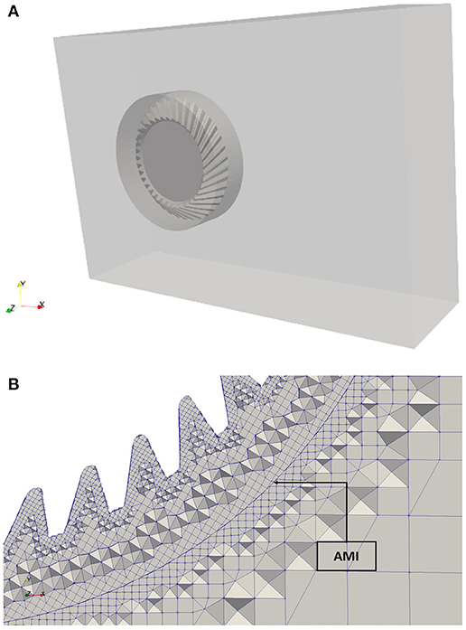
Figure 1. Geometrical discretization. (A) Computational domain (box, cylinder, and gear). (B) Detail of the mesh near the interface (on a 2D plane).
Solver Settings and Power Losses Calculation
The PIMPLE (merged PISO-SIMPLE) algorithm was used in both simulations. This algorithm allows a better control in transient simulations. In fact, it is possible to tune the correctors of the conservation equations within one timestep in order to reach the best compromise between computational effort and stability of the simulation. A convergence criterion of 1e-6 was imposed to all field's variables. The GAMG (Generalized Geometric-Algebraic Multi-Grid) solver was used for the pressure, since, in the authors experience, it is much faster than other solvers (like the PCG–Preconditioned Conjugate Gradient) in this kind of simulations. The velocity was solved with a smooth solver (Gauss-Seidel). The Courant number was limited to 1 to ensure the stability of the simulations. The first-order implicit Euler scheme was used for time-stepping. A Total Variation Diminishing (TVD) scheme using the vanLeer limiter was adopted for the convection of the volumetric fraction. The convective fluxes in the turbulence equations were discretized using second order schemes.
The mathematical formulation that enables the calculation of the power losses was implemented as a utility that reads the fields at each timestep and calculate inertial (Fpi) and viscous (Fτi) contribution of the losses. The initial transitory is characterized by a fluctuation of the forces which does not allow a correct evaluation of the efficiency of the gearbox. Therefore, it is necessary to observe the variation of these quantities in time. Once these do not oscillate too much and stabilize around a mean value within a certain percentage limit, the solution reached convergence and the fields can be post-processed to calculate the losses. The power loss of the gear is calculated as:
where ω is the angular velocity of the wheel and ri stands for the distance of each cell center of the wheel from its axis of rotation. The inertial and viscous forces are calculated as:
where pi and Ai represent the pressure and the area of the i-th cell. The impact of the volumetric fraction (air and oil mixture) on the no-load power losses is considered in Equation (14). Indeed, the first term represents the dynamic viscosity μ which is the product between the kinematic viscosity ν and the density ρ of the mixture in every computational cell of the gear. Since the multiphase condition is solved with the VOF method, the properties of the mixture are calculated according to Equations (5) and (6) and are directly included in the viscous contribution of the losses. Moreover, the presence of lubricant induces higher pressure forces on the gear causing an impact also on the inertial losses. Therefore, the volumetric fraction plays a key role in the amount of no-load losses. In addition, the gearbox filling level has a strong impact on the power losses [as evidenced by Höhn et al. (2011)]. This points out the importance of having accurate models to predict the efficiency and the lubrication capability of gearboxes in different operating conditions, in order to find the optimal amount of lubricant that ensures the proper lubrication of all the mechanical components and, at the same time, that limits the power losses arising from an excessive quantity of lubricant.
Tested Conditions
In this paper, the uncommon behavior of the losses in relation with rotational speed observed by Quiban et al. (2019) was studied with the opensource software OpenFOAM®. In fact, the torque increased until a certain rotational speed, then it decreased to a local minimum, and at higher velocities it restarted to increase.
When studying the lubrication of gearboxes several parameters can be varied to analyze their influence on the losses: geometrical configurations, physical properties of the oil, angular velocity, etc. To investigate the trend of the power dissipation, it was chosen to vary only one parameter, i.e., the rotational speed, and keep constant all the other parameters. The gear's geometrical characteristics are reported in Table 1. The properties of the lubricant are reported in Table 2.
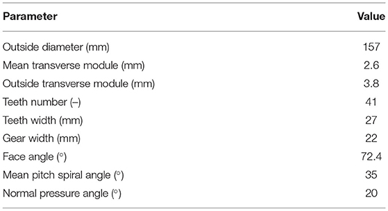
Table 1. Gear's geometry characteristics.
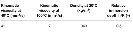
Table 2. Lubricant properties.
A constant temperature of 40°C was imposed in the simulations (isothermal condition). Therefore, the energy equation was not included in the calculations, and the viscosity (ν) and the density (ρ) of the lubricant were calculated according to the following equations based on the temperature (θ):
Results
The trend of the power losses with respect to the rotational speed is reported in Figure 2. The simulations' results agree quite well with the experiments, at least in the trend prediction, even if some discrepancies can be seen especially in the middle range and for very high rotational speeds. These discrepancies can be attributed to the modeling assumptions that have been made; namely the shaft was not modeled and the radial clearance from the box was assumed to be equal to 30 mm. As it can be noticed, in the first range of rotational velocities the power dissipation increases as normally observed in previous studies on gears. In the second one it decreases, while in the third one it restarts to increase. The increase in the power losses in the first range is due to the churning phenomenon. In the second range, most probably due to geometrical characteristics of spiral bevel gears (different diameters of the gear in the axial direction and the curved profile of the helical teeth that tend to eject a significant amount of lubricant contributing creating air pillows in the expelled region), the immersion depth diminishes, meaning that less oil resists to the wheel rotation, and thus the losses start to increase slowly. On the other hand, it should be considered that while less wetted, the gear continues to interact with the second fluid (namely air). The related windage effects, even with a lower slope, contribute to increase the total losses. The final trend of the total no-load losses (churning + windage) depends on how fast a specific gear geometry promote the formation of air pillows around the gear. The related wetting decrement velocity in combination with the power loss-velocity dependency is the basis for the final shape of the no-load loss curve. While at low velocities the power losses increase due to a combination of speed and wetted area increment, for high speeds, where the wetting remains almost constant, the increase of the power losses is directly related to the rotational speed. In the intermediate region, while the rotational speed increases, the sudden reduction of the wetted area of the gear leads to a flattening of the power loss-velocity trend. In order to quantify the amount of gear wetted area, a utility to extract the wetted surface from the simulations written in C++ was developed. In Figure 3 the oil (3A) and air (3B) wetted area of the gear at different rotational speeds is reported. The observed trends could be a possible justification for the strange shape of the power loss-speed curve.
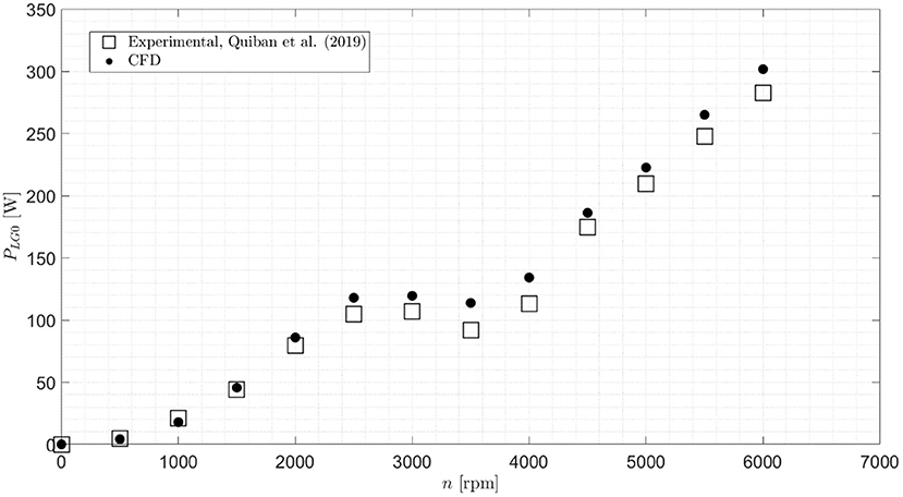
Figure 2. Experimental (Quiban et al., 2019)–Numerical comparison (power losses vs. rotational speed).
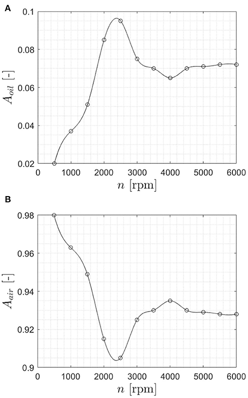
Figure 3. Comparison of the wetted area at different rotational speed. (A) Oil wetted area. (B) Air area.
In the middle range, the simulations predict an almost constant value of the losses rather than a decrease of it, as evidenced by experimental measurements (Quiban et al., 2019), but generally speaking the trend is captured by the numerical approach. Quiban et al. (2019) noticed that the oil flow rate is almost constant with the velocity of the wheels. After an initial increment of the expelled flow rate until 2500 rpm, it tends to stabilize to a lower value which is dependent on the decrement of the wheel's immersion depth. In Figure 4 it is possible to appreciate this phenomenon also in the simulations.
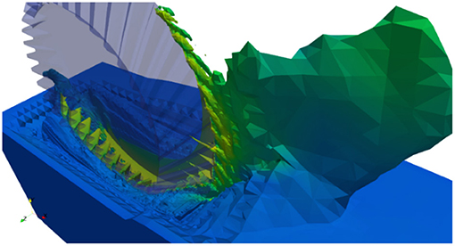
Figure 4. Local diminution of the immersion depth which decreases the losses.
In order to perform a differentiate analysis of the windage and churning effects, additional single-phase simulations with air were implemented in OpenFOAM®. From literature, it is well-known that these effects have a different impact on the power losses depending on the rotational speed of the wheel. In fact, at low-moderate velocities, churning is predominant and windage plays a marginal role, while at higher velocities the windage effects become preponderant (Quiban et al., 2019). In fact, the windage losses can be related to the rotational speed with a 3rd order exponent (), while the churning with a 1.65 exponent () (Dawson, 1984; Diab et al., 2004; Johnson et al., 2007). In Figure 5 the windage power losses of the gear are reported. It can be seen that the windage effects become more determinant as the rotational speed increases. In particular, after 3500–4000 rpm, the slope of the curve clearly indicates the apparition of windage effects that led to increasing power losses at high speeds.
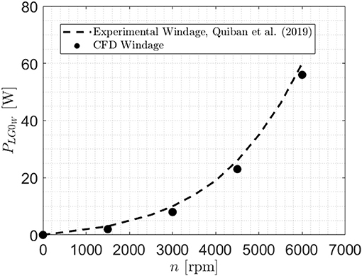
Figure 5. Experimental (Quiban et al., 2019)–Numerical comparison (windage power losses vs. rotational speed).
The simulations were performed on a Deploy LXD Compute Node (2xINTEL Xeon® E-2680, 8 Cores, 3.5 GHz). The computational time resulted in about 20 h per simulation for the multi-phase condition and 9 h for the single-phase one. The power losses at each timestep were averaged at the regime condition.
The numerical simulations allowed also to distinguish between pressure and viscous contribution to the losses. As expected, the inertial forces are predominant and represent the majority of the total losses. This highlights that the density is a much more influencing parameter than viscosity and, therefore, should be considered carefully in the design of mechanical gearboxes. Figure 6 shows the different contribution of pressure and viscous effects.
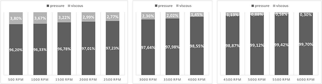
Figure 6. Pressure and viscous contribution to the total no-load losses at different rotational speeds subdivided for the three ranges.
The fact that the pressure forces represent the highest amount of the no-load losses is a constant not only for spur and helical gears (Concli et al., 2014), but was observed also in works with spiral bevel gears (Webb et al., 2010; Peng et al., 2019). Moreover, also the trend with respect to the rotational speed is the same. Indeed, the higher the rotational speed, the higher the pressure effects over the viscous one.
In Figure 7 the pressure and the volumetric fraction fields of the spiral bevel gear are shown.
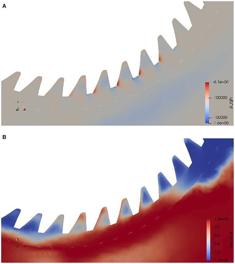
Figure 7. Graphical visualization of two fields on a 2D plane. (A) Pressure on the gear (with peaks on the teeth in contact with the lubricant). (B) Volumetric fraction field.
It can be noticed that when the teeth are in contact with the lubricant peaks of pressure values are present because of higher inertial forces.
The results of the simulations can provide useful information to engineers about the lubricant fluxes and the power losses in different operating conditions. All these aspects highlight once more the importance of the new technologies in computer science and their contribution to the development and optimization of mechanical systems. In particular, simulation's software packages based on CFD and FEM are increasing their importance in machine design and are nowadays key tools for engineers to investigate different conditions without the need of physical prototypes.
Discussion
This work focused on the implementation of a virtual model of a spiral bevel gear. This geometry was poorly touched in literature from a numerical point of view (if compared to spur and helical gears). The interesting behavior of the power losses observed experimentally was reproduced in the opensource environment OpenFOAM®. Although the results of the simulations showed some errors with respect to the experimental data, at least the main trend was captured. Experiments represents still the most accurate way of investigation. However, the technological advancements in computer science provide engineers the opportunity to speed up the design phase by implementing parametrical models that can provide a lot of information in a limited amount of time (if the modeling techniques are known by the user). This requires a deep knowledge of the most suitable models for the specific problem of interest. In this case, the simulation tool showed a good reliability, thus demonstrating the maturity of numerical tools and the possibility to gather a large amount of information not only on the efficiency, but also on the lubricant and pressure distribution.
Conclusions
The opensource software OpenFOAM® was used to investigate the power losses of a spiral bevel gear. The focus of this work was to examine the unusual behavior of the losses in relation with the rotational speed. In fact, three ranges were identified: from 500 to 2500 RPM (where the power losses increase with the rotational speed), from 3000 to 4000 RPM (where a decrease in the losses was observed experimentally and almost a constant value was predicted numerically), from 4000 to 6000 RPM (where the losses increase again due to the windage effects). The strange behavior of the losses can be explained with the local diminution of the immersion depth, on which the torque is dependent. The simulations can predict the trend of the losses, despite some discrepancies between experimental and numerical results, which can be explained through the model's assumptions that have been made during the implementation phase.
The subdivision of the power losses into pressure and viscous contribution provided interesting results. In fact, the pressure contribution is much higher than the viscous one. Moreover, this effect become even more evident at higher velocities, suggesting that the density of the lubricant has a more severe impact on the power dissipation than its viscosity.
The possibility to predict the internal fluid dynamics of gearboxes brings clear advantages in the reduction of physical prototypes and related costs. This points out that numerical approaches are an effective tool to design new and optimized gearboxes, and can be used by engineers to investigate virtual prototypes in various operating conditions in a reasonable amount of time. The methodology described in this work is based on a well-known dynamic mesh method (sliding mesh approach) which enables to study all the configurations in which no intersections among rotating domains has to be modeled, e.g., single rotating gears and, with some assumptions on the backlash, also planetary configurations.
Data Availability Statement
The raw data supporting the conclusions of this article will be made available by the authors, without undue reservation.
Author Contributions
MM: conceptualization, methodology, software, investigation, and writing–original draft. FC: conceptualization and writing–original draft. Both authors contributed to the article and approved the submitted version.
Conflict of Interest
The authors declare that the research was conducted in the absence of any commercial or financial relationships that could be construed as a potential conflict of interest.
References
Bianchini, C., Da Soghe, R., Errico, J. D., and Tarchi, L. (2017). “Computational analysis of windage losses in an epicyclic gear train,” in Proceedings of the ASME Turbo Expo, Vol. 5B-2017 [Charlotte, NC: American Society of Mechanical Engineers (ASME)].
Boness, R. J. (1989). Churning losses of discs and gears running partially submerged in oil. Proc. ASME Int. Power Trans. Gearing Conf. 1, 355–359.
Burberi, E., Fondelli, T., Andreini, A., Facchini, B., and Cipolla, L. (2016). “CFD simulations of a meshing gear pair,” in Proceedings of the ASME Turbo Expo, Vol 5A-2016 (Seoul: American Society of Mechanical Engineers).
Cavotta, M., Hotait, M., and Singh, A. (2018). A Computational Fluid Dynamics (CFD) Model for Gear Churning. SAE Tech. Pap. Warrendale, PA: SAE International.
Changenet, C., and Velex, P. (2007). A model for the prediction of churning losses in geared transmissions—preliminary results. ASME J. Mech. Des. 129, 128–133. doi: 10.1115/1.2403727
Concli, F. (2017). Low-loss gears precision planetary gearboxes: reduction of the load dependent power losses and efficiency estimation through a hybrid analytical-numerical optimization tool [Hochleistungs- und Präzisions-Planetengetriebe: Effizienzschätzung und Reduzierun Forsch. Eng. Eng. Res. 81, 395–407. doi: 10.1007/s10010-017-0242-0
Concli, F., and Gorla, C. (2013). Influence of lubricant temperature, lubricant level, and rotational speed on the churning power loss in an industrial planetary speed reducer: computational and experimental study. Int. J. Comput. Methods Exp. Meas. 1, 353–366. doi: 10.2495/CMEM-V1-N4-353-366
Concli, F., Gorla, C., Della Torre, A., and Montenegro, G. (2014). Windage power losses of ordinary gears: different cfd approaches aimed to the reduction of the computational effort. Lubricants 2, 162–176. doi: 10.3390/lubricants2040162
Concli, F., Gorla, C., Della Torre, A., and Montenegro, G. (2015). Churning power losses of ordinary gears: a new approach based on the internal fluid dynamics simulations. Lubr. Sci. 27, 313–326. doi: 10.1002/ls.1280
Daily, J., and Nece, R. (1960). Chamber Dimension effects of induced flow and frictional resistance of enclosed rotating disks ASME J. Basic Eng. 82, 217–232. doi: 10.1115/1.3662532
Dawson, P. (1984). Windage power losses in high speed gears. Arch. Proc. Inst. Mech. Eng. Part A Power Proc. Eng. 198, 51–59. doi: 10.1243/PIME_PROC_1984_198_007_02
Diab, Y., Ville, F., Velex, P., and Changenet, C. (2004). Windage losses in high speed gears-preliminary experimental and theoretical results. J. Mech. Des. Trans. ASME 126, 903–908. doi: 10.1115/1.1767815
Höhn, B. R., Michaelis, K., and Otto, H. P. (2011). “Influences on no-load gear losses.” in 3rd European Conference on Tribology (Wien), 639–644.
Hu, X., Jiang, Y., Luo, C., Feng, L., and Dai, Y. (2019). Churning power losses of a gearbox with spiral bevel geared transmission. Tribol. Int. 129, 398–406. doi: 10.1016/j.triboint.2018.08.041
Huang, S., Wei, Y., Guo, C., and Kang, W. (2019). Numerical simulation and performance prediction of centrifugal pump's full flow field based on OpenFOAM. Processes 7:605. doi: 10.3390/pr7090605
Johnson, G., Simmons, K., and Foord, C. (2007). “Experimental investigation into windage power loss from a shrouded spiral bevel gear,” in ASME Turbo Expo 2007 (Montreal, QC).
Kunz, R. F., Boger, D. A., Stinebring, D. R., Chyczewski, T. S., Lindau, J. W., Gibeling, H. J., et al. (2000). Preconditioned navier-stokes method for two-phase flows with application to cavitation prediction. Comput. Fluids 29, 849–875. doi: 10.1016/S0045-7930(99)00039-0
Lauster, E., and Boos, M. (1983). Zum Wärmehaushalt mechanischer Schaltgetriebe fьr Nutzfahrzeuge. VDI-Ber 488, 45–55.
Mann, R., and Marston, C. (1961). Friction drag on bladed disks in housings as a function of reynolds number, axial and radial clearance, and blade aspect ratio and solidity. ASME J. Basic Eng. 83, 719–723. doi: 10.1115/1.3662307
Mastrone, M. N., Hartono, E. A., Chernoray, V., and Concli, F. (2020). Oil distribution and churning losses of gearboxes: experimental and numerical analysis. Tribol. Int. 151:106496. doi: 10.1016/j.triboint.2020.106496
Mauz, W. (1987). Hydraulische Verluste von Strinradgetrieben bei Umfansgsgeschwindigkeiten bis 60 m/s. Stuttgart: Universität Stuttgart.
Merkle, C. L., Feng, J., and Buelow, P. E. O. (1998). “Computational modeling of the dynamics of sheet cavitation,” in 3rd International Symposium on Cavitation (Grenoble), 47–54.
Niemann, G., and Winter, H. (2003). Maschinenelemente—Band 2: Getriebe Allgemein,Zahnradgetriebe—Grundlagen, Stirnradgetriebe-−2.Auflage. Berlin: Springer.
Ohlendorf, H. (1958). Verlustleistung und Erwärmung von Stirnrädern. Munich: Technische Hochschule München.
Peng, Q., Gui, L., and Fan, Z. (2018). Numerical and experimental investigation of splashing oil flow in a hypoid gearbox. Eng. Appl. Comput. Fluid Mech. 12, 324–333. doi: 10.1080/19942060.2018.1432506
Peng, Q., Zhou, C., Gui, L., and Fan, Z. (2019). Investigation of the lubrication system in a vehicle axle: numerical model and experimental validation. Proc. Inst. Mech. Eng. Part D J. Automob. Eng. 233, 1232–1244. doi: 10.1177/0954407018766128
Petit, O., and Nilsson, H. (2013). Numerical investigations of unsteady flow in a centrifugal pump with a vaned diffuser. Int. J. Rotating Mach. 2013:961580. doi: 10.1155/2013/961580
Quiban, R., Changenet, C., Marchesse, Y., and Ville, F. (2019). Churning losses of spiral bevel gears at high rotational speed. https://journals.sagepub.com/home/pij Proc. Inst. Mech. Eng. Part J J. Eng. Tribol. 234, 172–182. doi: 10.1177/1350650119858236
Saurer, J. (2000). Instationären kaviterende Sträömung–Ein neues Modell, basierend auf Front Capturing (VoF) and Blasendynamik. Karlsruhe: Universität Karlsruhe.
Seetharaman, S., Kahraman, A., Moorhead, M. D., and Petry-Johnson, T. T. (2009). Oil churning power losses of a gear pair: experiments and model validation. J. Tribol. 131:022202. doi: 10.1115/1.3085942
Soo, S. L., and Princeton, N. J. (1958). Laminar flow over an enclosed rotating disk trans. ASME 80, 287–296.
Terekhov, A. S. (1975). Hydraulic losses in gearboxes with oil immersion. Vestn. Mashinostroeniya 55, 13–17.
Turner, A., Morvan, H. P., and Simons, K. (2013). “Two phase CFD modelling of a spiral bevel gear using particle injections and a wall film model,” in Proceedings of ASME Turbo Expo 2013: Turbine Technical Conference and Exposition GT2013 (San Antonio, TX).
Walter, P. (1982). Untersuchung Zur Tauchschmierung Von Stirnrädern Bei Umfangsgeschwindigkeiten Bis 60 M/S. Stuttgart: Universität Stuttgart.
Keywords: gears, power losses, efficiency, lubrication, CFD
Citation: Mastrone MN and Concli F (2021) Power Losses of Spiral Bevel Gears: An Analysis Based on Computational Fluid Dynamics. Front. Mech. Eng. 7:655266. doi: 10.3389/fmech.2021.655266
Received: 18 January 2021; Accepted: 20 April 2021;
Published: 20 May 2021.
Edited by:
Daniele Dini, Imperial College London, United KingdomReviewed by:
T. V. V. L. N. Rao, Madanapalle Institute of Technology and Science (MITS), IndiaLiran Ma, Tsinghua University, China
Copyright © 2021 Mastrone and Concli. This is an open-access article distributed under the terms of the Creative Commons Attribution License (CC BY). The use, distribution or reproduction in other forums is permitted, provided the original author(s) and the copyright owner(s) are credited and that the original publication in this journal is cited, in accordance with accepted academic practice. No use, distribution or reproduction is permitted which does not comply with these terms.
*Correspondence: Franco Concli, ZnJhbmNvLmNvbmNsaUB1bmliei5pdA==